A homemade bottle-jack press can handle small bearing, bushing, light-forming, and assembly work, but it can also store enough force to eject tooling or tear an unengineered frame apart. The safer approach is to treat the project as machine design: define the work, engineer the full load path, fabricate it to a qualified welding procedure, add guarding, and commission it under controlled conditions.
Quick Answer
Build a mini hydraulic press only after a qualified person checks the frame, welds, bed, pins, jack mount, anchorage, tooling, and guarding for the intended load. Use a bottle jack specifically approved for press service, keep every load centered, secure the press, and commission it behind a barrier with controlled load measurement.
Key Takeaways
- The jack’s marked capacity is not the finished press’s safe working load.
- Use known-grade steel and have the beams, columns, bed, pins, welds, tooling, and base checked as one load path.
- Use a jack approved for press service and never weld, drill, invert, or alter its relief system without written manufacturer approval.
- Install point-of-operation and fragment guarding before applying a test load.
- Do not compress springs, sealed objects, brittle unknown materials, or work held by improvised tooling.
At a Glance
| Time Required | One to two full fabrication days after the design is reviewed; machining, guarding, inspection, and controlled commissioning may require additional time. |
| Difficulty | Advanced fabrication. Structural design review, accurate drilling or machining, and qualified welding are required. |
| Tools Needed | Welder, metal-cutting equipment, drill press or machining equipment, clamps, squares, measuring tools, torque tools, guarding, lifting help, and appropriate PPE. |
| Cost | Variable. Price the specified steel, approved jack, machined pins, tooling, guarding, anchors, consumables, inspection, and professional review before starting. |
Warning: A homemade press has no valid tonnage rating merely because it contains a rated bottle jack. Until the complete machine has been reviewed, commissioned, and labeled by a qualified person, treat it as unrated and do not place it in service.
Materials and Tools You Need
Gather the specified materials before cutting. Do not substitute unknown scrap, rebar, unidentified bolts, or improvised press plates for parts in the reviewed design. Every load-bearing item needs a known material, size, and function.
- Press-approved hydraulic jack — Choose a bottle jack whose manufacturer permits the intended press configuration. Confirm its rated capacity, closed height, hydraulic stroke, extension-screw limits, operating orientation, and service requirements.
- Known-grade structural steel — Use the sections, plates, and dimensions specified in the reviewed design for the columns, base, top beam, bed beams, and moving ram plate.
- Press bed and arbor plates — Use flat, fully supported plates or tooling designed for the approved working load.
- Purpose-made support pins — Use matching pins with positive retention. Their diameter, material, hole fit, and supported span must be checked for shear, bending, and bearing.
- Ram guides — Use guide rods, wear strips, or bushings that keep the moving plate aligned without carrying the main pressing load or binding during travel.
- Jack mount — Fabricate a removable mechanical cradle or plate that captures the jack without welding or drilling its body.
- Guarding — Provide a properly designed point-of-operation and fragment-containment guard that does not create a new pinch or access hazard.
- Anchors and fasteners — Use specified structural fasteners and anchors for the base, jack mount, guides, and guards.
- Welding equipment — Use a process, filler metal, joint preparation, and settings covered by the written welding procedure for the selected steel.
- Cutting and machining tools — Use a suitable saw, grinder, drill press, reamer or boring equipment, deburring tools, clamps, and a rigid workholding setup.
- Inspection tools — Use squares, straightedges, calipers, torque tools, alignment indicators, and any inspection equipment specified by the reviewer.
- Safety equipment — Use welding protection, safety glasses, a face shield for pressing operations, gloves appropriate to the task, hearing protection, protective footwear, ventilation, and fire-control equipment.
Note: Material thickness alone does not establish strength. Section shape, unsupported length, hole placement, weld geometry, loading direction, steel grade, and local bearing conditions all affect the result.
Products Worth Considering

APPLICATION: Suitable for most 12.5-ton jacks on the market, meet all your maintenance needs

Package Included: 15 X Floor Jack Seal Kit O Ring (A*5+B*5+C*5)

APPLICATION: Suitable for most 20-ton vertical jacks to meet your multi-functional maintenance needs
Define the Work Envelope Before You Design the Frame
Start with the work the press must perform rather than with steel already lying around the shop. Record the largest approved workpiece, required force, tooling height, desired daylight, bed width, ram travel, and access needed to position the work without placing hands in the danger zone.
The ASME PASE-2024 standard covers the design, construction, marking, operation, maintenance, and inspection of shop presses and related portable automotive service equipment. A homemade machine may not carry a commercial certification, but its design review should address the same categories of risk.
- Closed height: Confirm that the jack, ram plate, tooling, and workpiece fit between the top beam and bed before the stroke begins.
- Useful stroke: Base the useful travel on the jack manufacturer’s permitted hydraulic stroke and extension-screw use, not on a forced overtravel.
- Daylight: Provide enough space for the work and tooling without using unstable towers of loose spacers.
- Bed positions: Use a reviewed hole pattern and matching support pins rather than slots or loose height-adjustment shims.
- Operator position: Locate the jack handle and release control so the operator remains outside the likely fragment path.
- Mounting location: Choose a rigid bench or floor location that can support the press, anchors, workpiece, and operating forces.
Design Overview and Key Decisions
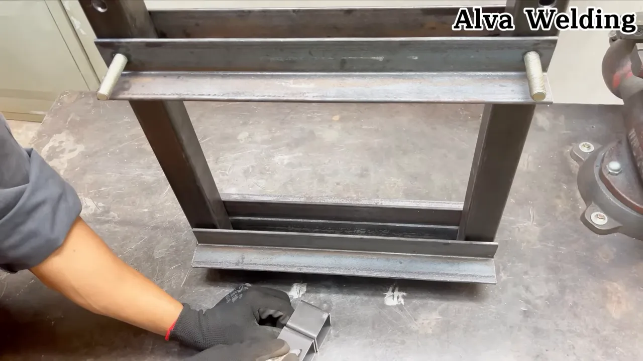
A compact H-frame with two vertical columns normally provides a more direct and symmetrical load path than an open C-frame. An open-sided design places large bending and twisting loads into the throat and should not be copied without a specific engineering analysis.
The press should transfer force from the jack through the top beam, columns, adjustable bed, support pins, tooling, and workpiece without introducing side load or allowing any member to buckle, twist, spread, or slide.
- Use two aligned columns and enough lateral restraint to prevent sideways movement.
- Design the top beam for global bending and for concentrated bearing where the jack saddle or bracket contacts it.
- Use a moving ram plate that remains square through its full stroke.
- Design the bed beams and support pins as structural components rather than general-purpose hardware.
- Provide a broad, anchored base that resists tipping and column spread.
- Keep the jack centered on the machine centerline and captured in the orientation approved by its manufacturer.
Products Worth Considering

Leak-Proof and Rust-Proof Materials:YELLOW JACKET 6 ton porta power kit are constructed of electrostatic powder spraying and heavy-duty steel.The capacity for all your repair needs and ideal for your workshop or garage.Sturdy and dutable. The meticulously crafted oil cylinder can reduce seal ring wear and improve service life. High wear resistance, high strength

Boost your Bull-Work Efficiency: The VEVOR porta power kit with a 10-ton hydraulic pump is the ultimate heavy-lifter you need for all your repair needs. The automatic overload system prevents any damage to the equipment or rams, while the hydraulic spreader with a 1/2 ton capacity makes all your repairs a breeze. Get your hands on this powerhouse today!

Leak-Proof and Rust-Proof Materials:YELLOW JACKET 4 ton porta power kit are constructed of electrostatic powder spraying and heavy-duty steel.The capacity for all your repair needs and ideal for your workshop or garage.Sturdy and dutable. The meticulously crafted oil cylinder can reduce seal ring wear and improve service life. High wear resistance, high strength
Engineering Checks That Establish the Working Load
A qualified designer should check each component and connection under the intended load, including appropriate design factors and foreseeable off-center conditions. The review should cover:
- Top-beam bending, shear, deflection, and local bearing
- Column compression, buckling, spreading, and connection loads
- Bed-beam bending, shear, deflection, and local crushing
- Support-pin shear, bending, bearing, retention, and hole tear-out
- Weld-group strength, joint restraint, fatigue, and inspection access
- Ram-plate bending and guide clearance
- Base-plate stability, bench or floor capacity, and anchor forces
- Arbor plates, adapters, dies, spacers, and workpiece support
- The jack mount and the contact surfaces at both ends of the jack
The approved working load can be no greater than the lowest verified capacity of the jack, frame, welds, bed, support pins, tooling, anchorage, and workpiece setup.
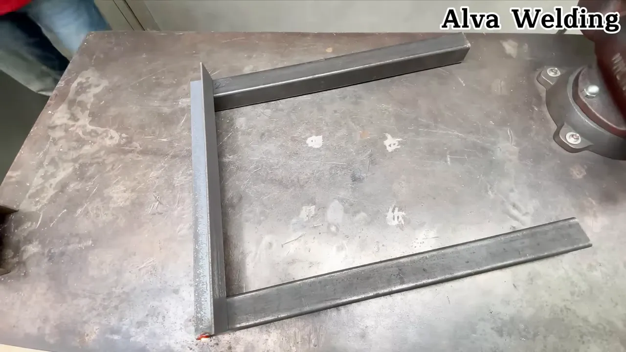
Cutting, Fitting, and Welding the Frame
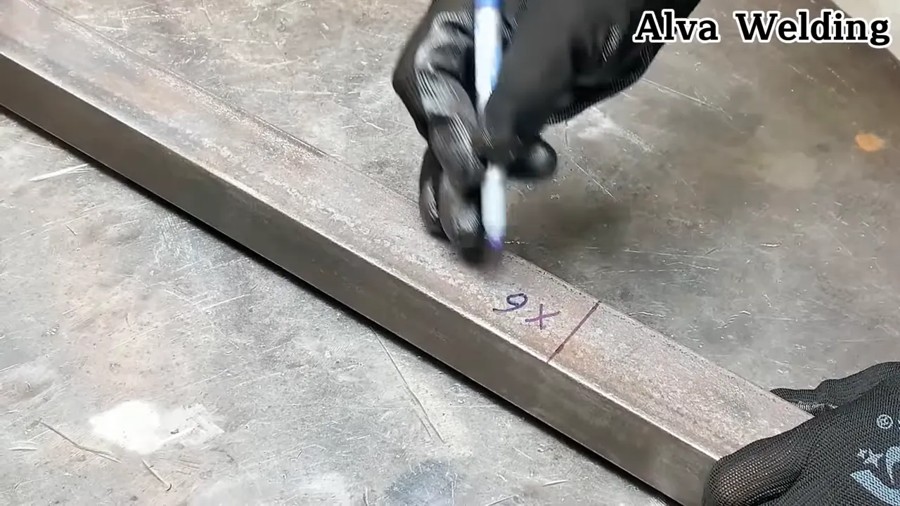
Accurate cutting and fitting reduce gaps, distortion, and unintended eccentric loading. They do not replace structural calculations or a qualified welding procedure. The current AWS D1.1/D1.1M structural steel welding code addresses welding procedures, welder qualification, fabrication, and inspection for commonly used structural steels.
- Verify the material. Confirm the grade, section dimensions, wall thickness, surface condition, and orientation of every structural part.
- Cut accurately. Make square cuts and smooth sharp edges without reducing the specified section.
- Prepare the joint. Remove oil, paint, rust, moisture, and mill scale as required by the welding procedure. Identify galvanized, lead-coated, or otherwise hazardous coatings before heating them.
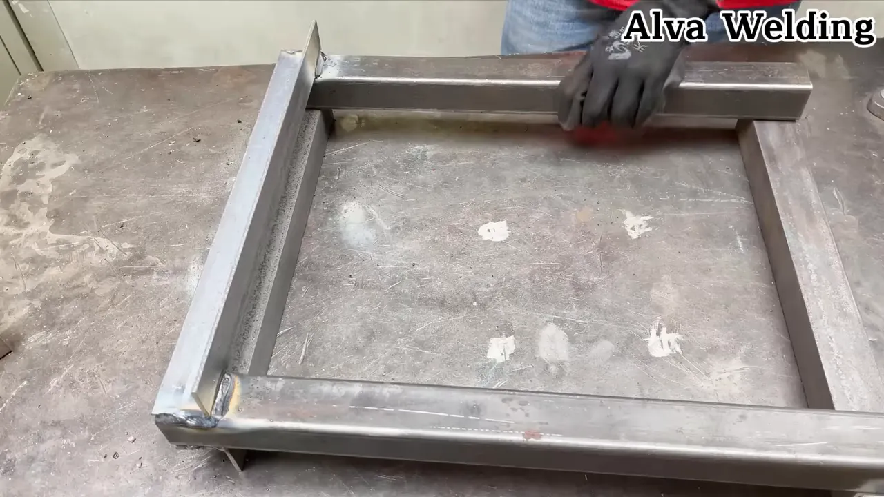
- Fixture the frame. Clamp the base, columns, and beams against rigid references so they remain square and parallel.
- Tack in sequence. Apply balanced tack welds, recheck diagonals and centerlines, and correct movement before final welding.
- Follow the written procedure. Use the specified joint details, filler metal, preheat, interpass control, weld size, sequence, and inspection method.
- Inspect before assembly. Have critical welds examined by a person qualified to apply the selected acceptance criteria.
Do not assume continuous welds or extra passes are always beneficial. Excess weld metal and poor sequencing can increase restraint and distortion while leaving the actual root or fusion problem unresolved.
Warning: Welding and grinding create fumes, ultraviolet radiation, hot metal, sparks, and fire hazards. Follow the ventilation, PPE, coating, and hot-work requirements described in OSHA 29 CFR 1910.252, remove or protect nearby combustibles, and never use oxygen as ventilation.
Assembly and Jack Mounting
Secure the jack so it cannot walk, tilt, rotate, or leave its contact surfaces. The jack must remain removable for inspection and service, and the mount must not alter the jack body or its hydraulic circuit.
- Place the base and columns in the reviewed fixture and confirm that the column centerlines, bed holes, and top-beam centerline agree with the drawing.
- Install the top beam and verify that its jack contact or bracket is centered and parallel to the bed.
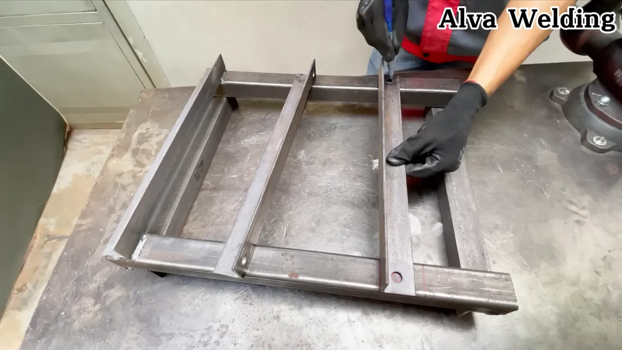
- Fit the bed beams and insert the matching support pins through the reviewed hole positions. Use the specified retaining method on every pin.
- Install the moving ram plate and guides. Confirm free travel through the full range before adding the jack.
- Place the bottle jack on its designed mounting plate in the manufacturer-approved orientation.
- Capture the jack base and saddle with removable brackets that prevent side movement without loading the reservoir, pump body, release valve, or handle mechanism.
- Install the specified guarding and confirm that it cannot contact the moving plate, jack, workpiece, or tooling.
- Anchor the completed frame to the reviewed bench or floor structure before commissioning.
Warning: Do not weld to the jack, drill its body, alter its relief valve, or invert it unless the jack manufacturer provides written instructions approving that exact use. A leaking, damaged, or incorrectly oriented jack must be removed from service.
Alignment, Guides, Press Bed, and Tooling
Hydraulic cylinders and jacks work best when the force remains centered on the plunger. Off-center loading can strain the jack, bend the ram plate, tilt the workpiece, and eject tooling. The hydraulic safety guidance from Enerpac advises centering loads and avoiding side load on cylinders and plungers.
Guide System
Guide rods or wear surfaces should control rotation and lateral movement of the ram plate without carrying the main pressing force. Misaligned or overly tight guides can bind and create the same side loading they are intended to prevent.
- Keep guide axes parallel to the press centerline.
- Provide the reviewed running clearance and lubrication method.
- Check travel with the jack removed and again during the no-load cycle.
- Stop if one guide wears faster, binds, or pulls the ram plate out of square.
Bed and Support Pins
The press bed normally rests on matching pins in double support, but the exact arrangement must be analyzed. Do not replace the specified pins with bolts, hitch pins, rebar, drill rod, or unidentified shafts merely because they fit the holes.
- Use matched pins made from the specified material and diameter.
- Keep holes aligned and within the reviewed fit and edge-distance limits.
- Use positive retainers so vibration or handling cannot move a pin.
- Support both sides of the bed evenly before applying pressure.
- Keep the pin, hole, and bed-contact surfaces free of burrs and debris.
Press Plates and Tooling
Use tooling and arbor plates designed for the approved working load and the intended operation. Keep each contact surface flat, clean, and fully seated. Do not build height with loose stacks of sockets, washers, short offcuts, or tapered scraps.
Note: Guides control alignment; they do not compensate for an off-center workpiece or undersized tooling. Reposition the setup rather than forcing a binding load.
Controlled Commissioning and Initial Use
Commissioning confirms that the machine matches its reviewed design; it does not consist of pumping the jack harder until something visibly moves. A competent person should prepare the test plan and establish the approved working load.
- Review the records. Confirm material identification, dimensions, weld procedure, welder qualification, inspection results, fastener specifications, tooling ratings, and anchor installation.
- Complete a no-load cycle. Run the jack through the permitted travel while checking ram alignment, guide clearance, return movement, handle access, and release control.
- Install all guards. Do not apply a commissioning load before the point-of-operation and fragment-containment guards are secured.
- Clear the area. Establish an exclusion zone and position the operator outside the likely line of fire.
- Measure force safely. Use the calibrated load-measurement method specified in the test plan. Do not estimate force from handle effort or jack extension.
- Load under controlled conditions. Apply and remove the prescribed stages behind the barrier, stopping immediately for movement, leakage, binding, permanent deformation, or unexpected noise.
- Inspect between stages. Unload the machine before examining welds, pins, holes, beams, anchors, jack seating, guards, and tooling.
- Document and label. Record the results and mark the approved working load, prohibited operations, inspection interval, and responsible reviewer on a durable label.
Warning: Do not conduct a full-jack-capacity trial from directly in front of the press. Visual stability during a light load does not prove that the frame, welds, pins, tooling, or anchors can safely withstand a larger load.
Safety Best Practices
A press creates crushing, pinch-point, sharp-edge, stored-energy, and ejected-part hazards. OSHA’s hydraulic-press machine-guarding guidance identifies the point of operation as a severe-injury area and describes barrier guards, safeguarding devices, and special hand tools for keeping the operator outside the danger zone.
- Keep hands, arms, feet, and all other body parts outside the guarded work area while the press is loaded or moving.
- Use tongs, fixtures, push tools, or another reviewed hands-off method to position and retrieve work.
- Wear safety glasses and suitable face protection, but do not treat PPE as a substitute for guarding.
- Keep bystanders outside the exclusion zone.
- Do not leave the press unattended while it is loaded.
- Do not move or adjust a workpiece while it remains compressed.
- Stop and release pressure if the workpiece tilts, tooling shifts, the jack leans, a guide binds, or the frame moves.
- Do not compress coil springs, leaf springs, gas springs, elastic assemblies, sealed containers, pressure vessels, batteries, ammunition, or unknown brittle objects.
- Do not use improvised dies or cutting tools. Press cutting requires engineered tooling, work support, clearance, and guarding designed for the cutting operation.
- Do not exceed the labeled working load or the rating of any adapter, plate, die, fixture, or work support.
- Do not place any body part beneath a load supported only by hydraulics.
- Release the load before maintenance. Where a test procedure requires mechanical restraint, use only the reviewed blocking system and install it without entering the danger zone.
Pro Tip: Mark the machine centerline on the ram plate, bed, and guard. The marks make small alignment errors easier to see before pressure is applied.
Maintenance, Inspection, and Safe Upgrades
Inspect the press before each use and at the documented periodic interval. Keep a dated log that records the work performed, unusual events, inspection findings, repairs, replacement parts, and the person who approved its return to service.
Pre-Use Inspection
- Check the jack for leakage, damaged controls, corrosion, drift, bent parts, and proper seating.
- Inspect welds for visible cracks, separation, corrosion, impact damage, or coating lines that suggest movement.
- Check beams, columns, plates, and the base for bending, dents, local crushing, or permanent spread.
- Remove and inspect support pins and retainers for bending, wear, galling, or damaged holes.
- Confirm that guides move freely and remain lubricated as specified.
- Inspect tooling and arbor plates for cracks, mushrooming, distortion, and damaged contact surfaces.
- Check anchors, guards, labels, and fasteners.
Hydraulic Maintenance
Follow the jack manufacturer’s oil, bleeding, storage, and service instructions. Do not search for a suspected high-pressure leak with a bare hand. Release pressure, remove the jack from service, and have it repaired by qualified personnel using approved parts.
Upgrades
- Larger base or additional anchorage: Have the modified base, supporting bench or floor, and anchor loads reviewed before use.
- Stronger beam or higher-capacity jack: Re-evaluate the entire machine. Strengthening one component does not increase the verified capacity of the pins, welds, bed, tooling, columns, or anchors.
- Pressure or force measurement: Do not drill or plumb a standard bottle jack. Use a purpose-built cylinder, pump, hose, valve, and gauge system rated and documented as a complete assembly.
- Improved guarding: Confirm that new panels, hinges, and fasteners contain the expected hazard without creating reach-around access or interfering with the moving load path.
Pro Tip: Photograph the unloaded press from the same marked positions during each periodic inspection. Side-by-side images can help reveal new spreading, misalignment, or permanent deformation.
Stop-Use Troubleshooting
| Jack leaks, drifts, or will not hold pressure | Release the load, tag the press out of service, and have the jack inspected or replaced with the approved model. |
| Ram plate travels unevenly | Stop. Check guide alignment, clearance, lubrication, jack seating, and frame squareness while unloaded. |
| Workpiece or tooling begins to tilt | Release pressure without entering the danger zone. Correct the setup, support, or tooling before restarting. |
| Pin is difficult to remove or shows a bend | Remove the press from service. Do not hammer the pin straight or replace it with an unapproved substitute. |
| Frame, anchor, or guard moves | Stop immediately, unload the machine, preserve the evidence, and obtain a structural review before reuse. |
| New crack, paint line, or permanent gap appears | Tag the press out of service. Do not grind over, reweld, or conceal the indication without an approved repair procedure. |
Quick Build Summary
- Define the intended tasks, force, stroke, daylight, bed positions, tooling, guarding, and mounting location.
- Have the complete frame, welds, bed, pins, guides, tooling, and anchorage reviewed for the intended load.
- Cut and fixture known-grade steel, then weld it using the approved procedure and inspection criteria.
- Install the adjustable bed, retained support pins, guided ram plate, press-approved jack mount, anchors, and guards.
- Complete a no-load check and controlled commissioning process before applying a documented working-load label.
- Use only approved centered setups and stop immediately for leakage, binding, tilting, movement, cracking, or permanent deformation.
A useful press is not merely one that produces force. It is one whose force, load path, tooling, guarding, and operating limits are understood and controlled.
Frequently Asked Questions
What size bottle jack should you use for a mini press?
There is no universal two-, four-, or six-ton answer. Define the required force, stroke, closed height, work envelope, and tooling first. Select a jack whose manufacturer approves the intended press arrangement, then have the complete frame and every other load-bearing component designed for the approved working load.
How do you know whether the press frame is strong enough?
Visual inspection and a light test are not enough. A qualified person must check the top beam, columns, bed, support pins, holes, welds, ram plate, base, anchors, and tooling. The completed machine then needs controlled commissioning and a documented working-load label.
Can you use the press for metal forming and cutting?
Use it only for operations covered by the design review and approved tooling. Light forming, bearing, bushing, and assembly work may be suitable when centered and guarded. Do not use improvised cutting dies. Cutting creates separate tool-strength, clearance, fragment, and guarding hazards.
Should you weld or bolt the jack cradle?
The surrounding cradle may use engineered welded or bolted connections, but the jack itself should remain removable and must not be welded or drilled. The mount must center both jack contact surfaces and prevent movement without damaging the jack body, pump, valve, or reservoir.
What should you check before each press use?
Check the jack, welds, beams, columns, bed, pins, holes, retainers, guides, ram plate, tooling, anchors, guards, labels, and fasteners. Look for leaks, drift, cracks, bending, spreading, corrosion, looseness, damaged tooling, or unusual movement. Remove the press from service until any problem is resolved.
Can you mount a standard bottle jack upside down?
Do so only when the jack manufacturer explicitly approves inverted operation. Many standard bottle jacks depend on reservoir orientation for proper oil pickup and venting. Use the manufacturer-approved orientation and a press arrangement designed around it.
Can you use a mini hydraulic press to compress springs?
No. Springs and other elastic assemblies store energy and can disengage violently. Use a purpose-built spring compressor designed and guarded for the exact spring instead of a general homemade shop press.
Can you add a pressure gauge to a bottle jack?
Do not drill, tap, or alter a standard bottle jack unless the manufacturer supplies an approved kit and instructions. For measured force, use a purpose-built press cylinder, pump, valve, hose, and gauge system whose pressure ratings and calibration are documented as a complete assembly.
Build Gallery and Visual Notes
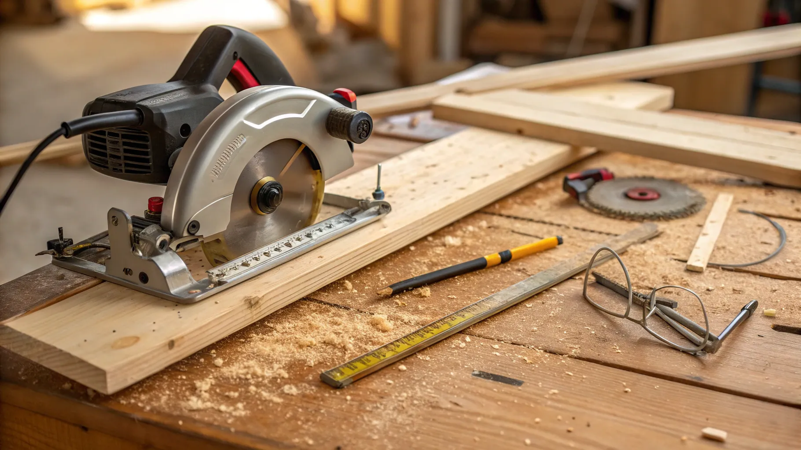
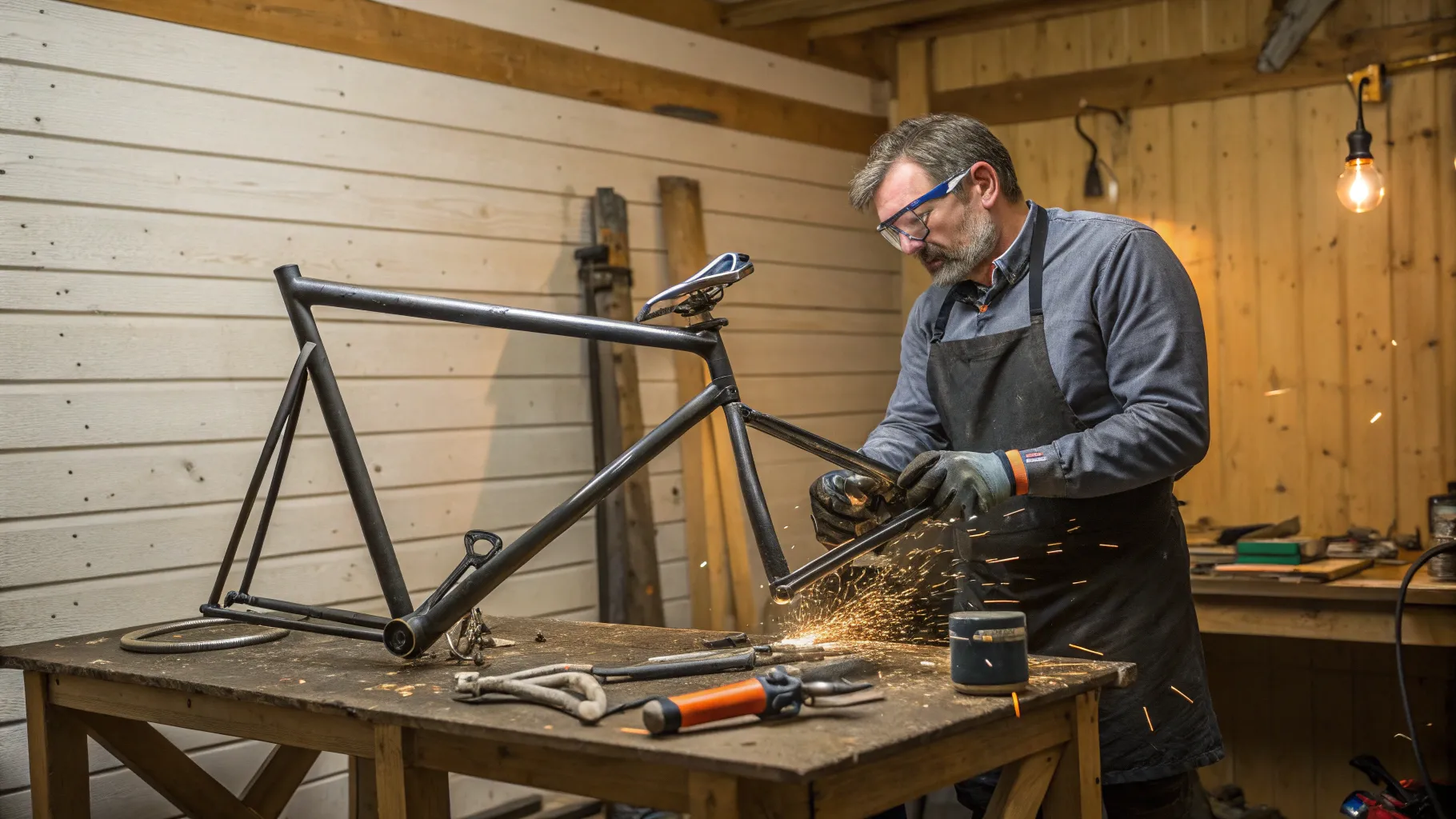
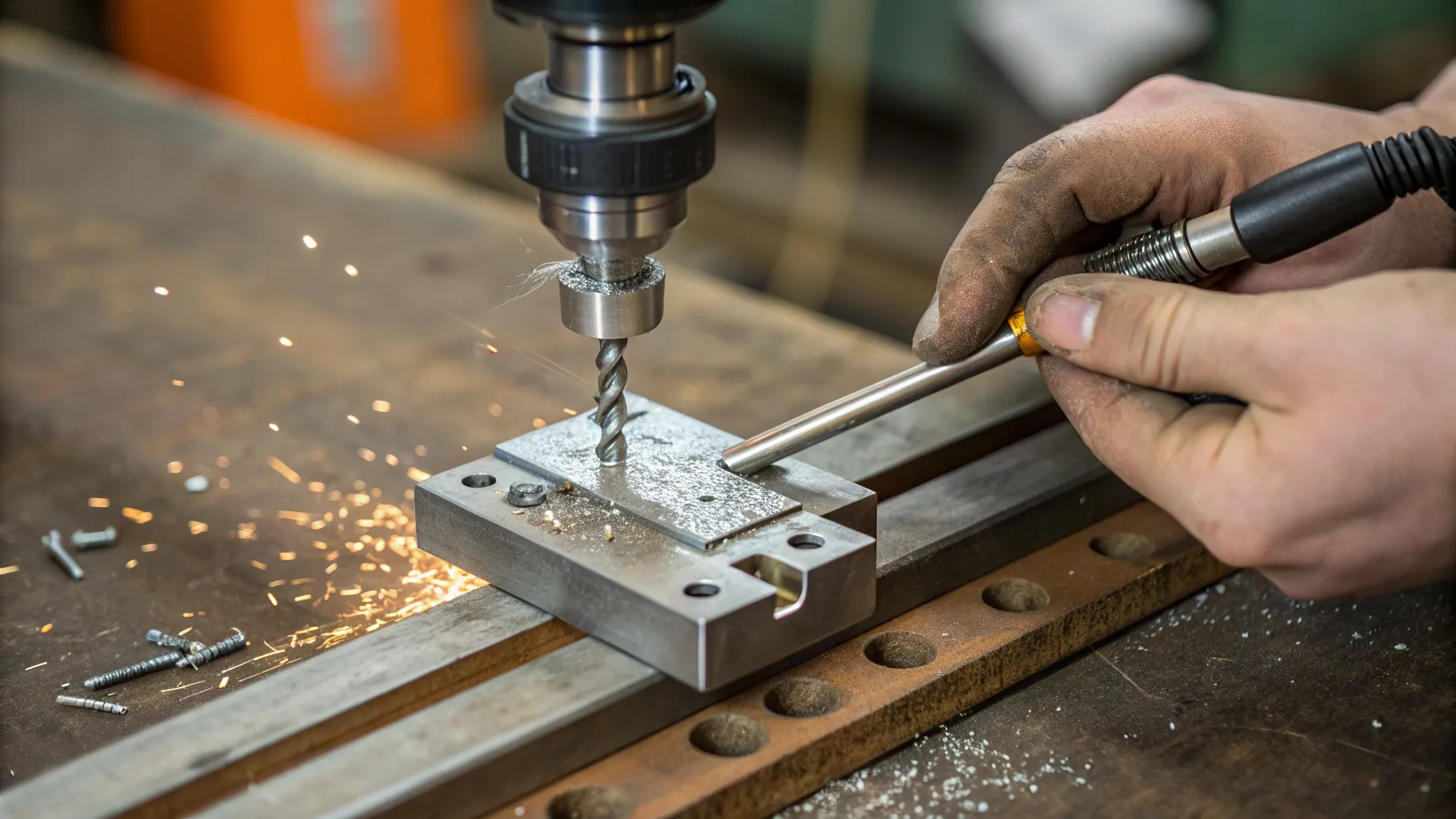
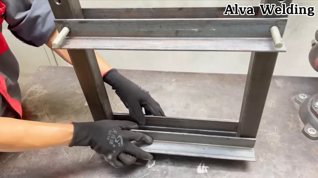
Use the images above to document general layout, welding access, jack positioning, guide alignment, and controlled testing. Do not copy a visible member size, weld, pin, or bracket solely from a photograph. Keep the reviewed drawing, material records, weld locations, inspection results, commissioning record, and maintenance log with the press.
Safety Disclaimer: This article is for general educational information and is not a certified press design, welding procedure, inspection plan, or proof-test specification. A homemade press remains unrated until a qualified engineer or machine designer reviews the complete assembly and a competent person documents its commissioning and working load. Workplace use may also be subject to OSHA, state, and local requirements.
Final Thoughts
A mini hydraulic press can become a useful shop tool when strength, alignment, guarding, tooling, and inspection are treated as parts of one system. Choose a jack approved for the intended configuration, use known materials, keep the force centered, and never infer machine capacity from the jack label alone. Controlled commissioning and a documented working load are essential before normal use.
Sources
- ASME PASE-2024: Safety Standard for Portable Automotive Service Equipment — Covers shop-press design, construction, marking, operation, maintenance, and inspection.
- OSHA Hydraulic Presses Machine-Guarding eTool — Supports point-of-operation guarding, control placement, and hands-off work practices.
- OSHA 29 CFR 1910.252: Welding, Cutting, and Brazing — Supports welding PPE, ventilation, coating, and hot-work precautions.
- Harbor Freight 20-Ton Shop Press Owner’s Manual — Supports jack centering, secure mounting, anchoring, guarding, inspection, and prohibited operations.
- Enerpac Hydraulic Safety Instructions — Supports centered loading, stable setups, mechanical load support, pressure control, and avoidance of cylinder modification.
- AWS D1.1/D1.1M:2025 Structural Welding Code—Steel — Supports welding-procedure, qualification, fabrication, and inspection requirements.