One of the biggest lessons I picked up early in the shop was realizing that a weld can look perfect on the surface yet fail when the real load arrives. That is why learning how to calculate weld strength matters. Whether you are using MIG for fabrication, TIG for controlled heat input, or stick electrodes for field work, bead appearance alone does not tell you the joint’s available strength.
Joint geometry, effective throat, weld length, load direction, filler-metal classification, base-metal strength, workmanship, and the governing code all affect the result. This guide explains the practical calculation process for common structural-steel fillet and groove welds while showing where a simple formula ends and a full connection design begins.
Quick Answer
To calculate weld strength, identify the governing code, load direction, weld type, effective throat, and effective length. For a simple equal-leg fillet weld, calculate the effective area as 0.707 × leg size × length, multiply by the code nominal stress, then apply LRFD or ASD factors and check the connected base metal.
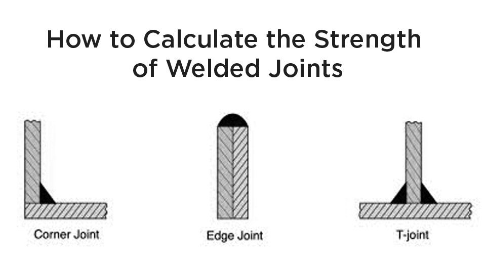
Image by extrudesign
Key Takeaways
- A weld calculation must compare the applied load with an available strength calculated by either LRFD or ASD. Do not mix the two methods.
- For an equal-leg 90° fillet weld, the theoretical effective throat is 0.707 times the weld leg size.
- The basic fillet-weld equation checks weld-metal strength only. The base metal, connection geometry, eccentricity, and fatigue may govern.
- A complete-joint-penetration groove weld with matching filler can develop the connected base metal, but the member must still be checked for yielding, rupture, and other applicable limit states.
- Safety-critical connections should be designed or reviewed by a qualified engineer and fabricated under an approved welding procedure specification.
At a Glance
| Time Required | About 10–20 minutes for a simple direct-load check; longer for eccentric weld groups, fatigue, or multiple limit states |
| Difficulty | Intermediate; professional engineering review is appropriate for structural, lifting, vehicle, pressure-boundary, or life-safety work |
| Tools Needed | Project drawings, design loads, material properties, verified weld dimensions, calculator, applicable code, and welding procedure specification |
| Cost | The calculation itself may cost nothing; code access, engineering review, procedure qualification, or nondestructive examination can add project cost |
Warning: The examples below are educational checks for straightforward structural-steel joints. Do not use them as the sole design basis for cranes, lifting devices, trailers, vehicle frames, pressure vessels, piping, bridges, occupied structures, fall-protection anchors, or other life-safety work. Use the code named in the contract and obtain qualified engineering review where failure could injure someone.
Why Weld Strength Matters
I learned this lesson early when a bracket that looked acceptable cracked after it was placed under a load I had not properly considered. The repair cost was frustrating, but the bigger lesson was that bead appearance and connection capacity are two different things.
A sound design must follow the complete load path. That means identifying how force enters the connection, how the weld group carries it, and how the force leaves through the connected base metal. Tension, shear, bending, torsion, impact, and repeated loading can produce very different demands even when the welds look similar.
Accurate calculations also prevent over-welding. A weld that is much larger than required takes more filler, labor, and heat input. It may increase distortion without improving the governing connection strength.
A strong-looking bead is not a design calculation. Weld-metal strength, base-metal strength, load direction, effective length, and fabrication quality must all work together.
Know the Scope Before Using a Weld Formula
This guide uses the structural-steel framework in ANSI/AISC 360-22 and the fabrication, qualification, and inspection framework in AWS D1.1/D1.1M:2025-AMD1. Your project may name a different edition, and the contract-specified edition controls.
AWS D1.1 covers welded structures made from commonly used carbon and low-alloy structural steels. It is not a universal code for aluminum, stainless steel, reinforcing bars, thin sheet steel, pressure vessels, pressure piping, aircraft, or vehicle crash structures. Those applications may require another AWS, ASME, API, AASHTO, aerospace, automotive, or manufacturer standard.
Note: AISC 360 establishes structural design strength, while AWS D1.1 addresses matters such as welding procedures, welder qualification, workmanship, inspection, and acceptance. A connection generally has to satisfy both the design requirements and the specified fabrication requirements.
Understanding Weld Joint Types
Before choosing an equation, identify both the joint arrangement and the weld type. A butt joint, lap joint, T-joint, corner joint, or edge joint describes how the pieces meet. A fillet, complete-joint-penetration groove, or partial-joint-penetration groove weld describes how the joint is welded.
Butt Joints and Groove Welds
A butt joint places two pieces end-to-end. It is commonly joined with a groove weld. The groove may be square, V-shaped, bevel-shaped, U-shaped, or another qualified configuration.
A complete-joint-penetration groove weld, or CJP weld, extends through the joint thickness. When it uses matching filler and satisfies the governing code, its design strength can be taken as that of the connected base metal for applicable load directions. A partial-joint-penetration groove weld, or PJP weld, has a defined effective throat smaller than the full joint thickness and must be calculated accordingly.
Pro Tip: Do not choose a universal bevel angle from plate thickness alone. Groove angle, root face, root opening, backing, electrode, position, and required penetration should come from the applicable prequalified joint detail or qualified WPS.
Fillet Welds
Fillet welds are used in T-joints, lap joints, and corner joints where connected surfaces meet at an angle. Their code effective area is based on the effective throat rather than the visible face width or the amount of convex reinforcement.
For an equal-leg 90° fillet, the theoretical effective throat is:
te = 0.707w
where w is the fillet leg size. The 0.707 factor does not automatically apply to unequal-leg fillets, skewed joints, flare grooves, or joints with a different included angle.
Lap Joints
A lap joint overlaps two pieces and commonly uses one or more fillet welds. The overlap can create eccentricity because the force may not pass through the same plane as the resisting weld group. That eccentricity can add a moment even when the applied force appears to be simple tension or shear.
Lap-joint strength therefore depends on more than whether the weld is placed on one side or two sides. Weld length, spacing, plate thickness, load direction, prying or opening action, connected-part strength, corrosion exposure, and fatigue can all affect the result.
Corner and Edge Joints
Corner and edge joints are common in boxes, tanks, cabinets, and light-gauge fabrication. They may be suitable for load-carrying work when properly detailed, but thin edges are vulnerable to burn-through, distortion, incomplete fusion, and local failure. Do not assume that an edge weld develops the full strength of the sheet.
Factors That Affect Weld Strength
Base Metal and Filler Metal
The base metal sets limits for yielding, rupture, shear, block shear, local failure, and fatigue. For example, ASTM A36 carbon structural steel is commonly associated with a 36-ksi minimum yield strength and a 58-ksi minimum tensile strength for the products covered by the specification. Confirm the actual material specification, thickness range, and certified properties rather than identifying steel by appearance alone. See the official ASTM A36/A36M specification page.
The filler classification provides the value commonly written as FEXX. An E70XX electrode or an ER70-series wire has a 70-ksi classification strength, but matching the number alone does not confirm that the filler is suitable for the material, service temperature, toughness requirement, position, process, or WPS.
Weld Size and Effective Length
For a fillet weld, increasing the leg size increases the effective throat. Increasing the effective length increases the effective area. However, the full physical length may not always be effective. End-loaded fillet welds with a high length-to-size ratio can require a reduction, and special connections such as HSS joints may have limited effective lengths.
A strength fillet weld should also satisfy the code’s minimum effective-length rules. A very short weld cannot automatically be credited at its full nominal leg size.
Load Direction and Weld-Group Geometry
A force parallel to a straight fillet weld produces a different response from a force perpendicular to it. AISC 360-22 permits a directional-strength factor for qualifying fillet welds, but restrictions apply. When you have not confirmed that the increase is permitted, using kds = 1.0 is the conservative approach.
Loads that do not pass through the weld-group centroid create a moment. The individual weld segments then carry different forces, so simply adding total weld length can be unsafe.
Welding Process and Procedure
MIG, flux-cored, stick, submerged arc, and TIG welding can all produce acceptable welds when the process, filler, joint, position, variables, and operator qualification meet the governing requirements. TIG is often selected for control and cleanliness, while MIG and flux-cored processes may offer higher production rates. The process name by itself does not create a higher code design strength.
Weld Quality and Inspection
Cracks, incomplete fusion, slag inclusions, unacceptable porosity, undercut, incorrect profile, and undersized welds can reduce performance. There is no universal percentage by which every discontinuity reduces strength. Acceptance depends on the discontinuity’s type, size, orientation, location, loading, and the criteria in the governing code.
Visual inspection is the starting point. Depending on the project, additional examination may include magnetic-particle, liquid-penetrant, ultrasonic, or radiographic testing. The selected method must be suitable for the material, joint, expected discontinuity, and applicable acceptance criteria.
Static, Impact, and Fatigue Loading
The basic formulas in this article address static available strength. Connections exposed to repeated cycles, vibration, fluctuating stress, impact, seismic demand, or low-temperature service need additional checks. For fatigue, the controlling variables may include stress range, detail category, weld termination, geometry, and number of cycles—not just the weld’s static capacity.
Inputs and Symbols You Need
Gather the following information before starting. Guessing one missing value can invalidate the entire result.
| Symbol or Input | Meaning | Typical U.S. Units |
|---|---|---|
| Ru | Factored required strength for LRFD | kips |
| Ra | Required service-load strength for ASD | kips |
| w | Fillet-weld leg size | in. |
| te | Effective throat | in. |
| Le | Effective weld length | in. |
| Awe | Effective weld area | in² |
| FEXX | Filler-metal classification strength | ksi |
| Fy | Specified base-metal yield strength | ksi |
| Fu | Specified base-metal tensile strength | ksi |
| kds | Permitted directional-strength factor | Dimensionless |
Keep units consistent. Multiplying an area in square inches by a stress in ksi produces a force in kips. One kip equals 1,000 pounds-force.
How to Calculate Weld Strength Step by Step
Step 1: Define the Applied Load and Load Path
Identify the magnitude, direction, and location of every applicable force and moment. Determine whether the load is tension, compression, shear, bending, torsion, or a combination. Use the required load combinations from the governing design standard rather than an estimated operating weight.
For a direct concentric load, the force may be divided over the effective weld area. For an eccentric load, calculate the direct force plus the moment-induced force in the weld group.
Step 2: Choose LRFD or ASD
AISC permits two design formats:
- LRFD: Compare the factored required strength, Ru, with the design strength, φRn.
- ASD: Compare the service-level required strength, Ra, with the allowable strength, Rn/Ω.
Do not apply an LRFD resistance factor to an ASD load or divide an LRFD result by an additional homemade safety factor. Use one complete design method consistently.
Step 3: Calculate the Effective Weld Area
For an equal-leg 90° fillet weld:
te = 0.707w
Awe = 0.707wLe
For two identical effective weld lines, the total area may be twice the area of one weld, provided both welds participate in the assumed load path.
Use the code effective length, not automatically the measured end-to-end length. For a very short strength weld, the credited size may be limited. For long end-loaded welds with L/w > 100, AISC requires an effective-length reduction. For L/w > 300, the credited effective length is limited to 180w.
Step 4: Calculate Fillet-Weld Nominal Strength
For a qualifying fillet weld under AISC 360-22:
Rn = FnwAwekds
with:
Fnw = 0.60FEXX
For an eligible weld loaded at an angle θ to its longitudinal axis, the directional factor is:
kds = 1.0 + 0.50sin1.5θ
The factor ranges from 1.0 for force parallel to the weld axis to a maximum of 1.5 for force perpendicular to the axis. Restrictions apply to its use, including certain single-sided and HSS connections. The official AISC fillet-weld guidance explains these limitations.
When the increase has not been confirmed as applicable, use:
kds = 1.0
The available weld-metal strength is then:
LRFD: φRn, with φ = 0.75
ASD: Rn/Ω, with Ω = 2.00
Fillet-Weld Example
Consider one ¼-in equal-leg fillet weld that is 6 in. long and made with an E70-class filler. Assume a direct load parallel to the weld axis, no effective-length reduction, and kds = 1.0.
Given:
w = 0.25 in.Le = 6 in.FEXX = 70 ksiFnw = 0.60 × 70 = 42 ksi
Effective area:
Awe = 0.707 × 0.25 × 6
Awe = 1.061 in²
Nominal weld-metal strength:
Rn = 42 × 1.061 × 1.0
Rn ≈ 44.5 kips
Available strength:
LRFD: φRn = 0.75 × 44.5 ≈ 33.4 kips
ASD: Rn/Ω = 44.5 ÷ 2.00 ≈ 22.3 kips
If the factored LRFD demand is 20 kips, this weld-metal check passes because:
20 kips < 33.4 kips
That does not complete the design. You must still check the connected base metal, load eccentricity, weld terminations, fit-up, minimum and maximum size rules, fatigue where applicable, and all other relevant limit states.
How to Calculate the Required Fillet Size
For a simple direct-load LRFD check using an equal-leg fillet weld:
wrequired = Ru ÷ [φ(0.60FEXX)(0.707Le)kds]
For ASD:
wrequired = RaΩ ÷ [(0.60FEXX)(0.707Le)kds]
Round the calculated result up to a practical weld size. Then verify that the selected size satisfies the code minimum, does not exceed the permitted edge size, can be deposited in the required position, and does not make the connected part govern.
Minimum and Maximum Fillet-Weld Sizes
A calculated fillet size may be smaller than the minimum permitted by AISC. For common U.S. customary sizes, the minimum is based on the thicker connected part:
| Thickness of Thicker Part | Minimum Fillet Leg Size |
|---|---|
| Up to ¼ in., inclusive | ⅛ in. |
| Over ¼ in. through ½ in. | 3⁄16 in. |
| Over ½ in. through ¾ in. | ¼ in. |
| Over ¾ in. | 5⁄16 in. |
Along the edge of material less than ¼ in. thick, the maximum fillet size is generally the material thickness. Along an edge ¼ in. thick or greater, the maximum is generally the thickness minus 1⁄16 in. unless the weld is specifically detailed to obtain full throat. Project drawings, AWS requirements, and the WPS may add restrictions.
Groove-Weld Strength and a Correct CJP Example
For a CJP groove weld with matching filler, the weld can develop the connected base metal for applicable loading. Do not add the visible cap reinforcement to the effective area. The connected member must still be checked for each applicable base-metal limit state.
Consider a ½-in-thick by 10-in-wide ASTM A36 plate with a full-width CJP groove weld. For this simplified example, assume:
Ag = 0.5 × 10 = 5.0 in²Ae = 5.0 in²Fy = 36 ksiFu = 58 ksi
Gross-section yielding:
Pn = FyAg
Pn = 36 × 5 = 180 kips

LRFD: 0.90 × 180 = 162 kips
ASD: 180 ÷ 1.67 ≈ 108 kips
Tensile rupture:
Pn = FuAe
Pn = 58 × 5 = 290 kips

LRFD: 0.75 × 290 = 217.5 kips
ASD: 290 ÷ 2.00 = 145 kips
For the assumptions above, yielding governs at approximately 162 kips LRFD or 108 kips ASD. A real connection may also require checks for shear lag, net-section reduction, block shear, local yielding, backing removal, toughness, fatigue, and other project-specific conditions.
A PJP groove weld cannot be treated as a full-thickness CJP weld. Use the effective throat established by the joint detail and governing code, then check both weld metal and base metal.
Step 5: Check the Connected Base Metal
The weld should not be stronger on paper than the material carrying force into it. Depending on the connection, check:
- Gross-section yielding
- Net-section tensile rupture
- Shear yielding and shear rupture
- Block shear
- Local yielding, crippling, bending, or tear-out
- HSS wall plastification, punching, or effective weld length
- Fatigue-sensitive base-metal and weld details
The available connection strength is the lowest applicable limit-state strength, not simply the fillet-weld result.
Step 6: Account for Eccentric Weld Groups
If a force does not pass through the weld-group centroid, calculate the moment:
M = Pe
where P is the applied force and e is the eccentricity. The weld group must resist both direct force and moment. Common analysis methods use the weld-group section properties or the instantaneous-center-of-rotation method.
Do not divide the load equally among all inches of weld when the geometry causes uneven demand. The most heavily loaded point in the weld group may control.
Step 7: Evaluate Fatigue When Loads Repeat
A connection that passes a static strength calculation can still crack under repeated stress cycles. Trailer components, machine frames, bridges, crane details, vibrating equipment, vehicle structures, and cyclically loaded brackets may be fatigue-sensitive.
Use the governing fatigue provisions to determine the applicable detail category, permitted stress range, and required life. Increasing weld size does not automatically repair a poor fatigue detail. Smooth force flow, proper termination, reduced stress concentration, qualified workmanship, and the correct detail category matter.
Practical Tips for Strong, Code-Compliant Welds
Products Worth Considering

MODEL: E7018 is a low-hydrogen iron powder type electrode that produces high quality x-ray welds. It can be used in all positions on AC or DC reverse polarity welding current.

ELECTRODE SPECIFICATION: E6013 welding rods with 3/32 inch diameter and 14-inch length, designed for general purpose arc welding applications on carbon steel materials

MODEL: E6013 is a mild-steel general purpose rod. It operates on AC or DC welding current and works well on low voltage AC machines.
Prepare the Joint to the WPS
Remove contaminants that interfere with the qualified process, including oil, moisture, heavy rust, paint, and unsuitable coatings. Prepare the groove, root face, root opening, backing, and alignment to the drawing and WPS. Do not grind away so much material that the finished part is undersized.
Fit-up gaps can change the actual throat, increase filler use, promote burn-through, or create distortion. AWS and AISC provide limits and corrective provisions for excessive root openings; do not improvise repairs without approval.
Use Procedure-Based Machine Settings
Voltage, amperage, wire-feed speed, polarity, shielding gas, travel speed, electrode diameter, and stick-out depend on the process, filler, position, joint, material thickness, and machine. A fixed setting such as “20 volts for a ¼-in weld” is not reliable across different machines and procedures.
For code work, use the approved WPS. For non-code practice, begin with the power-source and consumable manufacturer’s chart, make a representative test coupon, inspect the result, and adjust within the recommended range.
Select Filler Metal for the Whole Application
E7018 and ER70S-6 are common carbon-steel consumables, but neither is automatically correct for every joint. Match the filler to the base metal, required strength, toughness, hydrogen controls, position, process, polarity, and WPS.
E6010 is a cellulosic electrode known for a forceful, deep-penetrating arc and is often used for root passes and pipe work. Lincoln Electric lists deep arc penetration as a feature of its Fleetweld 5P E6010 electrode. That does not mean E6010 is permitted for every structural joint. The governing code, contract, material, procedure, and service requirements decide whether it is acceptable.
For stainless steel, aluminum, dissimilar metals, and low-temperature service, use the applicable material-specific filler selection rules rather than choosing only by nominal tensile strength.
Control Heat and Distortion
Oversized welds add heat. Use balanced weld sequences, adequate restraint, controlled interpass temperature, and the smallest code-compliant weld that satisfies the design. Excessive restraint can also promote cracking, so the fabrication sequence should be planned rather than improvised.
Inspect Before Applying Load
Visual inspection should confirm location, length, size, profile, termination, and freedom from unacceptable visible discontinuities. A weld gauge helps verify fillet leg size and profile, but it does not reveal internal fusion.
Use additional NDT when required by the code, contract, engineer, or service risk. Inspection must use the acceptance criteria for the correct weld type and loading condition.
Warning: Do not test a load-bearing weld by casually hanging weight from it, striking it, or standing beneath it. A proof test should use an engineer-approved load, calibrated equipment, restraints, an exclusion zone, defined acceptance criteria, and post-test inspection.
Follow Hot-Work Safety Requirements
Welding exposes workers to arc radiation, hot metal, electrical hazards, fire, fumes, gases, and flying particles. Use suitable eye and face protection, flame-resistant clothing, gloves, ventilation or local exhaust, and fire-prevention controls. Remove combustible materials and follow the site hot-work permit process where required.
OSHA’s welding, cutting, and brazing guidance and 29 CFR 1910.252 describe key workplace controls, including eye protection and personnel safety requirements.
Comparison Table: Common Welded Joint Options
| Joint or Weld Type | Common Uses | Main Advantage | Main Design Concern |
|---|---|---|---|
| CJP groove weld | Full-strength splices and butt joints | Can develop the connected base metal with matching filler | Preparation, access, qualification, inspection, and base-metal limit states |
| PJP groove weld | Connections that do not require full penetration | Less weld volume than a CJP joint in some details | Effective throat and load-direction limitations |
| Fillet weld | T-joints, lap joints, brackets, and stiffeners | Simple preparation and flexible detailing | Effective throat, length, eccentricity, minimum size, and base-metal strength |
| Lap joint | Plate connections and sheet fabrication | Easy fit-up and multiple weld arrangements | Eccentric load path, opening action, corrosion, and fatigue |
| Corner or edge joint | Boxes, cabinets, tanks, and light fabrication | Compact geometry | Thin-edge melting, distortion, local strength, and leakage |
Common Mistakes and How to Fix Them
Using gross weld length instead of effective length: Confirm returns, interruptions, end-loaded reductions, HSS effective lengths, and minimum-length rules before calculating area.
Mixing LRFD and ASD: Use factored loads with φRn or service loads with Rn/Ω. Do not combine factors from both methods.
Checking only the weld metal: Calculate the connected plate, shape, or HSS limit states. The base metal often governs before a large weld reaches its calculated capacity.
Assuming a bigger bead always helps: An oversized weld increases cost, heat input, shrinkage, and distortion. It cannot repair a weak load path or thin connected plate.
Crediting convexity or cap reinforcement: Use the code effective throat. Extra weld face material is generally not added to the design throat.
Using 0.707 for every fillet: The factor applies to an equal-leg 90° theoretical fillet. Use the correct geometry for unequal legs, skewed joints, or flare grooves.
Ignoring eccentricity: Calculate the moment created by the distance between the load line and weld-group centroid.
Treating static strength as fatigue strength: Use the applicable fatigue provisions when loads repeat.
Choosing filler by tensile number alone: Confirm process, hydrogen classification, toughness, position, polarity, material compatibility, and the WPS.
Repairing defects without a plan: Grinding and rewelding can remove base metal, add heat, or create new cracks. Follow an approved repair procedure and reinspect the repaired area.
Real-World Applications
In building construction, weld calculations transfer beam reactions, brace forces, column-splice forces, and equipment loads through connections. In machinery, welded frames must resist direct loads, vibration, and local deformation. In gates, workbenches, and farm repairs, the same principles help prevent weak brackets and overloaded attachment points.
Some applications need much more than the simple examples above. Trailer hitches, motorcycle frames, roll cages, lifting lugs, cranes, pressure systems, and crash-loaded vehicle components are safety-critical and often governed by specialized standards, fatigue requirements, testing, and professional responsibility. A basic fillet-weld formula should not be treated as approval for those designs.
Products Worth Considering

☆ Upgraded Trailer Alignment Kit With Magnet Hitch Line Up is towing facility for aligning hitch with the trailers.

Helps limit lateral trailer movement to reduce sway
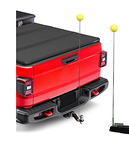
52" TALL EASILY VISIBLE: Align your hitch and ball mount the first time every time. The steel rods extend to 52" and can be seen above any oversized truck beds, day or night
Conclusion
Calculating welded-joint strength starts with the load path—not the bead. Identify the governing code, choose LRFD or ASD, determine the correct effective throat and length, calculate the weld-metal strength, and then check every applicable base-metal and connection limit state.
For a simple equal-leg fillet weld, 0.707wL provides the effective area and 0.60FEXX provides the basic AISC nominal stress. That calculation is only one part of the job. Effective-length limits, directional loading, eccentricity, yielding, rupture, block shear, fatigue, procedure qualification, workmanship, and inspection can change the final answer.
Use the edition named in the project documents, follow the approved WPS, and involve a qualified engineer whenever failure could threaten people, property, or essential equipment.
Frequently Asked Questions
What is the formula for fillet-weld strength?
For an equal-leg 90° fillet under AISC 360-22, the effective area is commonly Awe = 0.707wLe. Nominal weld strength is Rn = 0.60FEXXAwekds. LRFD uses φ = 0.75, while ASD uses Ω = 2.00. Restrictions and connected-part checks still apply.
How do I calculate the required fillet-weld size?
For a simple direct-load LRFD check, divide the factored required strength by φ × 0.60FEXX × 0.707Le × kds. Round up to a practical size, then check minimum and maximum weld size, effective length, connected base metal, eccentricity, and fatigue.
Does a larger fillet weld always make a connection stronger?
No. A larger weld increases weld-metal area, but the connected plate, block shear path, HSS wall, local bending, or fatigue detail may govern. Oversized welds also add heat, cost, shrinkage, and distortion.
How do I choose the right filler metal?
Match the filler to the base metal, required strength, toughness, hydrogen controls, process, welding position, polarity, service conditions, and approved WPS. A matching tensile classification alone does not prove that a filler is suitable.
Why do welded joints crack?
Possible causes include hydrogen, unsuitable filler, excessive restraint, poor joint preparation, rapid cooling, incorrect heat input, crater cracking, fatigue, lamellar tearing, or an overloaded connection. The crack should be evaluated before repair so the underlying cause is not repeated.
Can I calculate weld strength without testing?
You can calculate design strength from specified material properties and code equations, but calculations do not prove that the finished weld was deposited correctly. Code work may require qualified procedures, qualified welders, visual inspection, and specified NDT or testing.
What is the difference between tensile and shear strength in a weld?
Tension pulls material apart across a section, while shear causes adjacent portions to slide relative to each other. A real weld group can experience both, along with bending or torsion. Use the equations and interaction requirements for the actual force direction and joint geometry.
When should a professional engineer review the weld design?
Professional review is appropriate when the connection supports people, lifting equipment, vehicles, occupied structures, pressure systems, fall protection, public infrastructure, or costly machinery, or when the load is eccentric, cyclic, impact-driven, seismic, or otherwise difficult to define.
Sources
- American Institute of Steel Construction — ANSI/AISC 360-22 — structural-steel design requirements, LRFD and ASD, weld and connected-part strength
- American Welding Society — AWS D1.1/D1.1M:2025-AMD1 — structural-steel welding, qualification, fabrication, inspection, and acceptance
- AISC Engineering FAQ 8.3 — Fillet Welds — directional strength, fit-up, profiles, undersize limits, and edge-size guidance
- ASTM International — A36/A36M Carbon Structural Steel — material scope and tensile-property requirements
- Occupational Safety and Health Administration — Welding, Cutting, and Brazing — welding hazards, controls, and worker-safety resources
- Lincoln Electric — Fleetweld 5P E6010 — manufacturer information confirming deep arc penetration and typical electrode characteristics