Oxy-acetylene pressure settings are not universal. The correct setting depends on the exact torch handle, tip family, tip size, hose, fuel gas, and application. A chart can give you a safe starting point only when it matches your equipment. You must then set the regulators while gas is flowing, adjust the flame at the torch, and confirm the result on clean scrap metal.
Quick Answer
Set oxygen and acetylene from the chart for your exact torch tip, not from a universal PSI range. Choose the tip for the metal thickness, leak-test the system, purge each hose separately, and set pressure while gas is flowing. For mild-steel welding, adjust the torch to a neutral flame and never use acetylene above 15 psig.
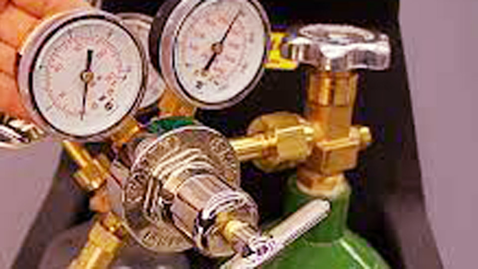
Original image credit: hotrod. Treat the image as a general reference and verify every setting against the manual for your torch and tip series.
Key Takeaways
- Tip numbers and pressure requirements are specific to the manufacturer and tip family.
- Set working pressure while the correct torch valve is open and gas is flowing.
- Use a neutral flame for most mild-steel welding unless the approved procedure specifies another flame.
- Never use acetylene above 15 psig, and do not assume 15 PSI is the correct operating setting.
- Leak-test, purge, wear the correct PPE, remove fire hazards, and shut the system down in the sequence required by its manual.
At a Glance
| Time Required | About 10–15 minutes for inspection, setup, leak testing, purging, and flame adjustment |
| Difficulty | Intermediate; first-time users should receive hands-on instruction from a qualified person |
| Tools Needed | Matched oxygen and acetylene equipment, correct tip, approved striker, oil-free leak solution, tip cleaner, PPE, and fire extinguisher |
| Cost | Varies by equipment, cylinder arrangement, gas supplier, tip, and required safety equipment |
Last updated: July 20, 2026.
Warning: Oxy-acetylene equipment can cause fire, explosion, serious burns, eye injury, and exposure to hazardous fumes. This guide does not replace the torch manual, cylinder supplier instructions, workplace training, hot-work rules, or supervision by a qualified person.
How Oxy-Acetylene Welding Pressure Settings Work
Oxy-acetylene welding combines oxygen and acetylene in a torch to produce an intensely hot flame, commonly described as roughly 5,700–6,000°F depending on the flame zone and reference. The flame melts the edges of the base metal, and you may add a compatible filler rod to complete the joint.
The regulator does not directly select a neutral, carburizing, or oxidizing flame. Its job is to reduce cylinder pressure and supply the flow required by the chosen tip. After you set the correct flowing pressures, you use the torch valves to adjust the final oxygen-to-acetylene ratio and flame shape.
Pressure that is too low for the tip can cause a weak, unstable flame, overheating, popping, or flashback. Excessive pressure can make the flame harsh, waste gas, disturb the puddle, and exceed the equipment’s rating. The correct setting must satisfy both pressure and flow requirements.
The number on a welding tip is not a universal size. Always match the pressure chart to the tip manufacturer, series, fuel gas, torch, and hose arrangement.
Static Pressure Versus Flowing Pressure
A regulator may show one pressure while the torch valves are closed and a lower pressure when gas is moving through the hose and tip. The value that matters during operation is the flowing pressure specified by the manufacturer.
To set it correctly, purge one hose at a time and adjust that regulator while the matching gas is flowing through the torch. Close the valve after the pressure stabilizes, then repeat the process for the other gas.
Why Two Correct Charts Can Show Different Pressures
Different tip families use different internal passages, mixers, hose sizes, and operating pressures. For example, the Hobart/Victor Type 13 chart below specifies relatively low welding pressures. A separate Miller Smith welding-tip chart specifies 10 psig for each gas on many SW, MW, and AW tips. Both charts can be correct for the equipment they cover.
Note: Do not use the table below for Smith, Harris, Victor tip families other than Type 13, imported look-alike tips, cutting attachments, rosebuds, or alternate fuel gases unless the equipment manual explicitly lists the same settings.
Oxy-Acetylene Welding Pressure Settings Chart for Steel
The following values come from the welding and brazing guide for a Hobart medium-duty outfit using Victor-compatible Type 13 tips. They are starting ranges for that specific equipment family, not a universal chart.
| Type 13 Tip Size | Material Thickness | Acetylene Pressure | Oxygen Pressure | Typical Flame |
|---|---|---|---|---|
| 000 | 28–22 gauge | 3–5 PSI | 3–5 PSI | Neutral for mild steel |
| 00 | 22–16 gauge | 3–5 PSI | 3–5 PSI | Neutral for mild steel |
| 0 | 16–14 gauge | 3–5 PSI | 3–5 PSI | Neutral for mild steel |
| 1 | 14–12 gauge | 4–6 PSI | 3–5 PSI | Neutral for mild steel |
| 2 | 12–10 gauge | 4–6 PSI | 3–5 PSI | Neutral for mild steel |
| 3 | 1/8–3/16 inch | 5–7 PSI | 3–5 PSI | Neutral for mild steel |
Source: Hobart Medium-Duty Oxy-Acetylene Equipment Owner’s Manual. Use the latest manual supplied with your equipment if its values differ.
For steel thicker than the listed range, do not estimate a larger tip or extrapolate the pressure. Use the table for the exact optional tip and torch. Heavy welding and heating may demand more acetylene flow than one cylinder can safely supply, even when the regulator pressure remains below 15 psig.
Pro Tip: Write the approved tip number and flowing pressures on a tag attached to the torch cart. This reduces the chance of accidentally using cutting or heating settings with a welding tip.
Welding, Cutting, Brazing, and Heating Use Different Settings
Do not transfer welding pressures to a cutting attachment or rosebud. Cutting uses a preheat flame plus a separate high-flow cutting-oxygen jet. Heating tips may require enough gas flow to need larger hoses, high-capacity regulators, or multiple acetylene cylinders.
Example Cutting Pressures for the Same Hobart Equipment Family
This table is included only to show how sharply cutting settings can differ from welding settings. It applies to the cited Hobart cutting-tip chart.
| Cutting Tip Size | Listed Steel Thickness | Acetylene Pressure | Oxygen Pressure |
|---|---|---|---|
| 00 | 1/4 inch | 3–5 PSI | 20–25 PSI |
| 0 | 1/2 inch | 3–5 PSI | 25–30 PSI |
| 1 | 9/16 inch | 3–5 PSI | 30–35 PSI |
| 2 | 3/4 inch | 3–6 PSI | 35–40 PSI |
| 3 | 1-1/2 inches | 4–8 PSI | 40–45 PSI |
The listed thickness is a chart capacity for that tip, not a promise that every cut will be clean. Steel condition, oxygen purity, torch distance, hose loss, preheat adjustment, and operator speed also affect the cut.
Heating Tips and Cylinder Capacity
A multi-flame heating tip may consume far more acetylene than a welding tip. High withdrawal can pull solvent from an acetylene cylinder, starve the flame, or make the tip unstable. Use the tip maker’s consumption chart to confirm the required cylinder capacity and number of cylinders. Consult the gas supplier before manifolding cylinders.
Check that any added flashback arrestor can pass the required flow. An arrestor that is safe for a small welding tip may be too restrictive for a high-output heating tip.
Step-by-Step Guide to Setting Oxy-Acetylene Pressure
- Read the equipment chart. Confirm the torch model, tip series, tip number, fuel gas, material thickness, hose size, and required flowing pressures.
- Prepare the work area. Remove combustible material, provide ventilation, place an appropriate extinguisher nearby, and arrange a fire watch when required.
- Secure both cylinders upright. Use a suitable cart, chain, or strap. Keep cylinders away from sparks, hot slag, traffic, and electrical circuits.
- Inspect the complete system. Check the regulators, gauges, hoses, fittings, torch valves, tip seat, O-rings, check valves, and flashback arrestors. Do not use equipment with damage, oil, grease, dirt, or deformed fittings.
- Back out both regulator adjusting screws. Close both torch valves before opening either cylinder.
- Open the cylinder valves correctly. Stand to the side of each regulator. Open the oxygen valve slowly and then fully unless its manufacturer specifies otherwise. Open the acetylene valve only about 1/2–3/4 turn, or as directed by the cylinder and torch manufacturers, so it can be closed quickly.
- Leak-test the system. Use an approved oil-free leak-detection solution on every connection. Never test for leaks with a flame. Shut the system down if bubbles continue after a connection is correctly tightened.
- Purge and set oxygen. In a ventilated area away from ignition sources, open only the torch oxygen valve. Purge for the duration specified in the manual and adjust the oxygen regulator to the chart value while oxygen is flowing. Close the valve.
- Purge and set acetylene. Open only the torch fuel valve, purge it separately, and adjust the acetylene regulator to the listed flowing pressure. Close the valve.
- Light the acetylene. Open the torch fuel valve slightly and ignite it with an approved friction striker. Never use a cigarette lighter, butane lighter, or match.
- Establish adequate fuel flow. Increase the acetylene at the torch until the black soot disappears and the flame is stable without lifting excessively from the tip.
- Add oxygen at the torch. Open the torch oxygen valve slowly until the acetylene feather disappears and a sharp, well-defined inner cone forms for a neutral flame.
- Test on clean scrap. Confirm that the flame remains attached, the tip does not overheat, and the puddle forms without excessive soot, oxidation, popping, or burn-through.
Warning: Do not crack an acetylene cylinder valve to blow dust from the outlet. Never direct oxygen at clothing, skin, equipment, or a work surface, and never use oxygen for cleaning, cooling, or ventilation.
Choosing the Right Welding Tip Size
Tip size controls gas flow and total heat output. A tip that is too small may force you to travel slowly and overheat a wide area without achieving proper fusion. A tip that is too large can create burn-through, distortion, an oversized puddle, and poor control.
Match the tip to the thickness range in its own manual. In the Hobart/Victor Type 13 example, size 2 covers 12–10 gauge material, while size 3 covers 1/8–3/16 inch. Another manufacturer may use entirely different numbers.
Clean a dirty tip with the correct smooth tip cleaner. Do not drill the orifice, force an oversized cleaner through it, or reshape the opening. An enlarged or irregular orifice can produce a wandering or unbalanced flame.
Products Worth Considering

Drill-type tip cleaner

Product Type:Tools

Stainless steel wire files for cleaning the gas orifices of cutting and brazing tips.
How Hose Length and Accessories Affect Pressure
Long, narrow hoses create pressure loss. Couplers, restrictive check valves, flashback arrestors, and undersized fittings can add more resistance. Some manufacturer charts assume a specific hose length and inside diameter, so a long hose may require a different regulator setting or a larger hose.
Do not compensate blindly by turning up the regulator. Check the manufacturer’s hose-loss table and make sure the complete system can deliver the required flow without exceeding any component rating.
Flame Types and Material Compatibility
Neutral Flame
A neutral flame has a sharp inner cone without a visible acetylene feather. It is the normal choice for most mild-steel gas welding. Set the approved flowing pressures first, then adjust the torch valves until the neutral flame is stable.
Carburizing or Reducing Flame
A carburizing flame contains excess acetylene and has a visible feather beyond the inner cone. Some specialized procedures use a slightly reducing flame, but excessive acetylene can deposit soot, add unwanted carbon, reduce heat concentration, and destabilize the flame.
Oxidizing Flame
An oxidizing flame contains excess oxygen and usually has a shorter, sharper cone with a harsher sound. Some brass and specialized nonferrous procedures may call for a controlled slightly oxidizing flame. Do not use it on steel unless the approved procedure requires it because it can increase oxidation.
Recommended Settings for Different Materials
The base material influences tip size, filler, flux, joint design, and required flame chemistry. It does not create one universal regulator-pressure range. Start with the exact tip chart, then follow the welding procedure for the material.
Mild Steel
Use a neutral flame unless the procedure specifies otherwise. Remove oil, paint, rust, plating, and scale from the joint. Choose a tip that supplies enough heat to form the puddle without forcing you to hold the flame in one place.
Aluminum
Oxy-acetylene welding of aluminum requires careful oxide removal, a compatible aluminum filler, the correct flux where required, and tight heat control. Use the pressure specified for the exact tip. Depending on the alloy and approved procedure, the flame may be neutral or slightly reducing.
Clean the joint with a dedicated stainless-steel brush that has not been used on steel. Aluminum’s oxide melts at a much higher temperature than the base metal, so poor cleaning can make the surface appear solid while the underlying aluminum overheats.
Copper and Brass
Copper carries heat away quickly and may require a larger tip or preheating than a steel part of similar thickness. Brass can lose zinc if overheated. Use the flame type, filler, flux, and heat input recommended by the filler-metal and procedure specifications.
Pressure Settings for Brazing
Brazing heats the joint above the filler metal’s melting temperature without melting the base material. It often uses a neutral or slightly reducing flame, depending on the base metal and filler system.
Do not assume brazing always needs one low-pressure range. Tip size still determines the required pressure and flow. The Hobart Type 13 chart above is labeled for both welding and brazing, with acetylene values from 3–7 PSI and oxygen values from 3–5 PSI across the listed tips. Those numbers apply only to that equipment family.
Heat the joint evenly and allow the base metal to melt the filler. Avoid holding the filler rod directly in the hottest part of the flame until it drips onto a joint that is still too cold.
Safety Considerations
Acetylene Pressure Limit
OSHA 29 CFR 1910.253 prohibits acetylene from being utilized above 15 psig. This is a maximum limit, not a normal target. Most welding tips operate below it.
Check Valves and Flashback Arrestors
A reverse-flow check valve helps stop gas from flowing backward into the wrong hose. It does not necessarily stop a flame. A flashback arrestor normally combines reverse-flow protection with a flame-arresting element and may include thermal or pressure protection.
Use the configuration approved by the equipment manufacturer. Do not automatically stack check valves and flashback arrestors at both ends of every hose. Extra devices can reduce flow, which is especially important with large cutting and heating tips.
Eye and Face Protection
OSHA’s filter-lens table lists these minimum protective shades:
| Operation | Material Thickness | Minimum Shade |
|---|---|---|
| Light gas welding | Under 1/8 inch | 4 |
| Medium gas welding | 1/8–1/2 inch | 5 |
| Heavy gas welding | Over 1/2 inch | 6 |
| Torch brazing | Not thickness-based in the OSHA table | 3 |
Start with a darker appropriate lens and move lighter only when needed for visibility, without going below the minimum. Wear approved safety glasses with side protection beneath suitable welding goggles or a face shield when flying particles and hot metal are present.
Fire Prevention
OSHA’s general welding requirements call for moving combustible material at least 35 feet from the work where practical. Protect material that cannot be moved, check hidden areas on the opposite side of walls or floors, and use a trained fire watch when the conditions require one.
Keep a suitable extinguisher ready. Mark or guard hot metal after the work so another person does not touch it or place combustible material against it.
Cylinder Handling and Storage
Keep cylinders upright and secured. Close cylinder valves when work is finished and before moving the cylinders. Keep oxygen equipment completely free of oil and grease.
For cylinders in storage, OSHA requires oxygen cylinders to be separated from fuel-gas cylinders or combustible materials by at least 20 feet, or by an approved noncombustible barrier at least 5 feet high with the required fire-resistance rating. The classification of an in-use or ready-to-use cart can differ from stored reserve cylinders, so follow the applicable workplace and fire-code rules.
Ventilation, Coatings, and Confined Spaces
Provide enough ventilation to control fumes and gases. Paint, galvanizing, plating, flux, oils, and cleaning residues can produce hazardous fumes when heated. Remove coatings where practical and use appropriate local exhaust or respiratory protection based on the hazard assessment.
Never use oxygen for ventilation. Do not take cylinders into a confined space. Confined-space hot work requires atmospheric testing, ventilation, an attendant, and a planned rescue procedure where applicable.
Do not weld, braze, heat, or cut a drum, tank, pipe, or other container that held a combustible or toxic substance unless it has been professionally cleaned, isolated, vented, tested, and prepared under an approved hot-work procedure.
Common Pressure and Flame Problems
| Symptom | Likely Causes | Safe Correction |
|---|---|---|
| Black soot | Too little oxygen at the torch, insufficient fuel flow before oxygen is added, dirty tip, or contaminated work | Return to the chart settings, establish adequate acetylene flow, add oxygen to the required flame, and clean the tip and joint |
| Flame lifts from the tip | Excess gas velocity, excessive pressure, wrong tip, damaged tip seat, or incompatible fuel tip | Shut down, confirm the tip and pressure chart, inspect the tip and seat, and reset flowing pressure |
| Repeated popping | Tip touching the work, overheated tip, low flow, loose tip, damaged seat, dirty orifice, or incorrect pressure | Stop, cool the equipment, clean and inspect the tip, tighten it correctly, and verify flowing pressure |
| Weak or slow puddle | Tip too small, travel too fast, excessive torch distance, pressure loss, poor preparation, or insufficient cylinder flow | Do not simply add oxygen; verify tip selection, neutral flame, hose capacity, torch distance, and joint preparation |
| Oxidized or rough puddle | Oxidizing flame, dirty base metal, wrong filler, or excessive heat | Reset the correct flame, clean the joint, confirm filler compatibility, and improve heat control |
| Pressure drops during use | Empty cylinder, freezing or excessive withdrawal, hose restriction, undersized arrestor, regulator fault, or leak | Stop and inspect the supply, flow requirements, hoses, protection devices, regulator, and connections |
| Gauge pressure rises after flow stops | Possible regulator creep or seat leakage | Remove the regulator from service and have it inspected by qualified personnel |
Backfire Versus Flashback
A backfire is a pop in which the flame briefly goes out or returns to the tip. It can result from tip contact, overheating, low flow, dirt, or an incorrect setting.
A flashback is more serious. The flame burns inside the torch, mixer, hose, or upstream equipment and may produce a squealing or hissing sound. If a flashback occurs, close the torch oxygen valve immediately, close the torch fuel valve, close both cylinder valves, and allow the equipment to cool. Do not relight it until the cause has been found and corrected. Remove damaged or suspect equipment from service.
Joint Preparation for Stronger Welds
Pressure settings cannot compensate for poor preparation. Remove oil, grease, moisture, paint, plating, rust, and scale from the weld area. Keep oxygen equipment away from oily tools, gloves, and cleaning products.
Square edges may be suitable for thin material. Thicker joints often require a bevel, root opening, or multiple passes according to the joint design. Fit and tack the work so the gap remains consistent as the metal heats and expands.
Test the complete setup on scrap of the same alloy and thickness. This lets you confirm tip size, travel speed, filler diameter, torch angle, and distortion control before welding the actual part.
Filler Rod Selection and Compatibility
Choose filler rod by base-metal composition, required strength and ductility, service conditions, and the applicable welding procedure. RG45 and RG60 are different steel gas-welding rod classifications and should not be treated as interchangeable defaults.
Match aluminum filler to the alloy and service conditions. Use the filler and flux manufacturer’s instructions for cleaning, flame chemistry, working temperature, and flux removal.
Match filler diameter to the joint and puddle size. Add the rod at the leading edge of the molten puddle so the heat from the joint melts it. Avoid melting the rod separately in the outer flame and dropping unmixed metal onto the surface.
Equipment Recommendations
Choose an approved, matched torch outfit from a manufacturer that provides accessible tip charts, manuals, replacement parts, and service support. Established systems are available from brands such as Victor, Harris, Smith/Miller, and Hobart, but brand reputation does not make charts interchangeable.
Use regulators intended for the correct gas and pressure range. Oxygen connections normally use right-hand threads, while many fuel-gas hose fittings use left-hand threads and identifying notches. Never force a fitting or use an improvised adapter.
Use industrial oxy-fuel hose approved for the gases in service. A dual-gauge regulator shows cylinder pressure and delivery pressure, but its accuracy and flow capacity must be appropriate for the tip.
Products Worth Considering
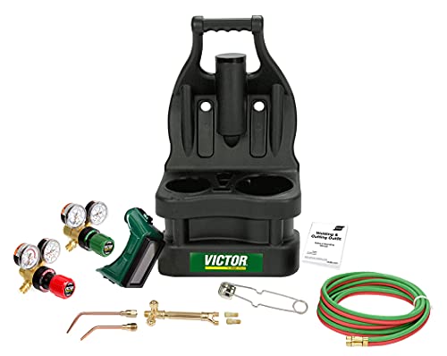
The Portable Tote from Victor features a molded, plastic carrying case with an ergonomic handle and balanced design for easy carrying.
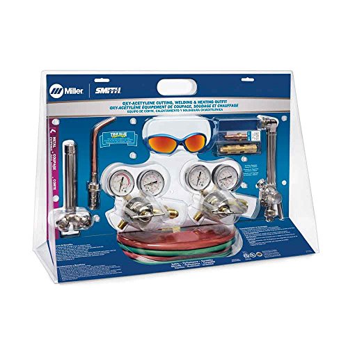
Fuel: Acetylene
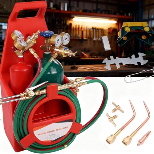
🎇【 High Purity Brass Material 】 — The oxygen acetylene torch kit is designed with high purity brass structure,which has high hardness, is not easy to break, and is rust-proof and corrosion-resistant. Featuring clear gauge design, real-time pressure data is displayed to avoid affecting processing quality due to pressure imbalance, it helps display accurate pressure.
Oxy-Acetylene Versus Other Welding Processes
Oxy-acetylene equipment can weld, braze, heat, and cut without electrical power at the point of use. It offers direct control over heat placement and remains useful for repairs, thin sheet, tube work, heating, and field situations.
MIG is usually faster for production welding and easier to automate. TIG offers precise arc control and avoids combustion gases at the torch. Oxy-acetylene is slower and introduces cylinder, flame, fire, and fuel-gas hazards, but one correctly equipped system can perform several processes.
Choose the process according to the material, thickness, required weld properties, location, production rate, available power, procedure requirements, and operator training.
Real-World Applications
- Automotive work: Controlled heating, brazing, exhaust repair, and some thin-steel welding where the approved repair procedure permits it.
- Farm and field repair: Heating fasteners, brazing, cutting carbon steel, and completing repairs where electrical power is limited.
- Art and fabrication: Forming, texturing, brazing, and welding small steel components.
- Pipe and maintenance work: Heating, brazing, and approved welding or cutting operations performed under the required procedure and permit system.
- Jewelry and fine work: Small specialized torches with their own tips, gases, pressure charts, and safety instructions.
Pros and Cons of Oxy-Acetylene Welding
Advantages
- No electrical power is required at the torch.
- The same matched system can weld, braze, heat, and cut with the correct attachments.
- Heat input and puddle development are easy to observe.
- The equipment can be transported on an approved cylinder cart.
Limitations
- Gas welding is slower than many arc-welding processes.
- The broad heat-affected area can increase distortion.
- Cylinders, hoses, flames, and hot work create significant fire and explosion hazards.
- Good results require practice in flame adjustment, puddle control, filler addition, and travel speed.
- Some alloys and code work require another process or a qualified welding procedure.
Maintaining Oxy-Acetylene Equipment
- Inspect hoses, regulators, gauges, fittings, torch valves, O-rings, tip seats, check valves, and flashback arrestors before use.
- Leak-test whenever the system is assembled, a cylinder is changed, or a connection is disturbed.
- Keep oxygen components completely free of oil, grease, petroleum-based sealants, and contaminated gloves.
- Clean tips with the proper cleaner without enlarging or reshaping the orifice.
- Protect hoses from hot metal, slag, sharp edges, traffic, chemicals, and flux.
- Follow the manufacturer’s inspection, testing, and replacement schedule.
- Have regulators, valves, arrestors, and damaged torches serviced by qualified personnel. Do not improvise internal repairs.
- Store equipment in a clean, dry area with cylinder valves closed and protective caps fitted where required.
How to Shut Down the Torch
Shutdown sequences can vary by equipment, so the manual takes priority. The following sequence matches the cited Miller welding-tip instructions:
- Close the torch oxygen valve to extinguish the flame.
- Close the torch fuel valve.
- Close the oxygen and acetylene cylinder valves.
- Open the torch oxygen valve and allow the line pressure to fall to zero.
- Close the oxygen valve and back out the oxygen regulator adjusting screw.
- Open the torch fuel valve and allow the line pressure to fall to zero.
- Close the fuel valve and back out the fuel regulator adjusting screw.
- Check the work area for flame, sparks, glowing material, and heat that could ignite nearby objects.
Do not leave the system pressurized between work sessions. Closing only the torch valves does not isolate a leaking regulator, hose, or connection from the cylinders.
Conclusion
The safest oxy-acetylene pressure chart is the one published for your exact torch and tip. Identify the tip family, choose the size for the material, set both regulators while gas is flowing, and adjust the torch to the flame required by the welding procedure. Never use acetylene above 15 psig, and never substitute generic internet pressures for the equipment manual.
Consistent welds also depend on clean joints, compatible filler, sufficient gas flow, correct torch distance, ventilation, suitable eye protection, and disciplined shutdown. When the flame pops, wanders, overheats, or loses pressure, stop and correct the cause instead of turning up a regulator at random.
Frequently Asked Questions
What are standard oxy-acetylene pressure settings for welding steel?
There is no safe universal setting. Use the chart for the exact torch and tip family. For example, the Hobart/Victor Type 13 chart in this article lists 3–7 PSI acetylene and 3–5 PSI oxygen across tips 000–3, while other tip systems specify different pressures.
Why can’t acetylene be used above 15 PSI?
Acetylene becomes hazardous when utilized at excessive pressure. OSHA prohibits its use above 15 psig. This is a maximum limit, not a recommended setting, and your tip chart will normally specify a lower pressure.
Should torch pressure be set with the valves open or closed?
Set the working pressure while the matching gas is flowing through the torch. Purge and adjust oxygen and acetylene separately. A gauge reading with the torch closed is a static reading and may not show the pressure available during use.
How do I light an oxy-acetylene welding tip safely?
Leak-test and purge both hoses first. Open the torch acetylene valve slightly, ignite it with an approved friction striker, increase fuel flow until soot disappears, and then add oxygen slowly until the required flame forms. Never use a cigarette lighter or match.
What is the difference between welding and cutting pressures?
A welding tip mixes oxygen and fuel to heat and melt the joint. A cutting attachment also supplies a separate high-flow oxygen jet that oxidizes and removes hot steel. Cutting oxygen is therefore often much higher, but the exact value still comes from the cutting-tip chart.
Can I weld aluminum with oxy-acetylene?
Yes, when the alloy and repair procedure permit it. Use a compatible aluminum filler and flux where required, remove the oxide with a dedicated stainless brush, select pressure from the exact tip chart, and follow the approved flame recommendation. Do not rely on one universal aluminum PSI range.
Why does my oxy-acetylene torch keep popping?
Common causes include touching the tip to the work, an overheated or dirty tip, insufficient gas flow, incorrect flowing pressure, a loose tip, a damaged seat, or a restrictive hose or arrestor. Shut down, cool the equipment, inspect it, and correct the cause before relighting.
Sources
- OSHA 29 CFR 1910.253, Oxygen-Fuel Gas Welding and Cutting — acetylene pressure, cylinders, equipment, storage, and handling requirements
- OSHA 29 CFR 1910.252, General Welding Requirements — fire prevention, eye protection, ventilation, confined spaces, and hot-work precautions
- OSHA 29 CFR 1910.133, Eye and Face Protection — minimum filter shades for gas welding, brazing, and oxygen cutting
- Hobart Medium-Duty Oxy-Acetylene Equipment Owner’s Manual — Type 13 welding, brazing, and cutting pressure examples
- Miller Oxy-Fuel Safety Manual — inspection, purging, lighting, flashback protection, operation, and shutdown procedures
- Miller, 10 Steps for Safe Oxy-Fuel Torch Setup — flowing pressure, valve opening, leak testing, and manufacturer-chart guidance