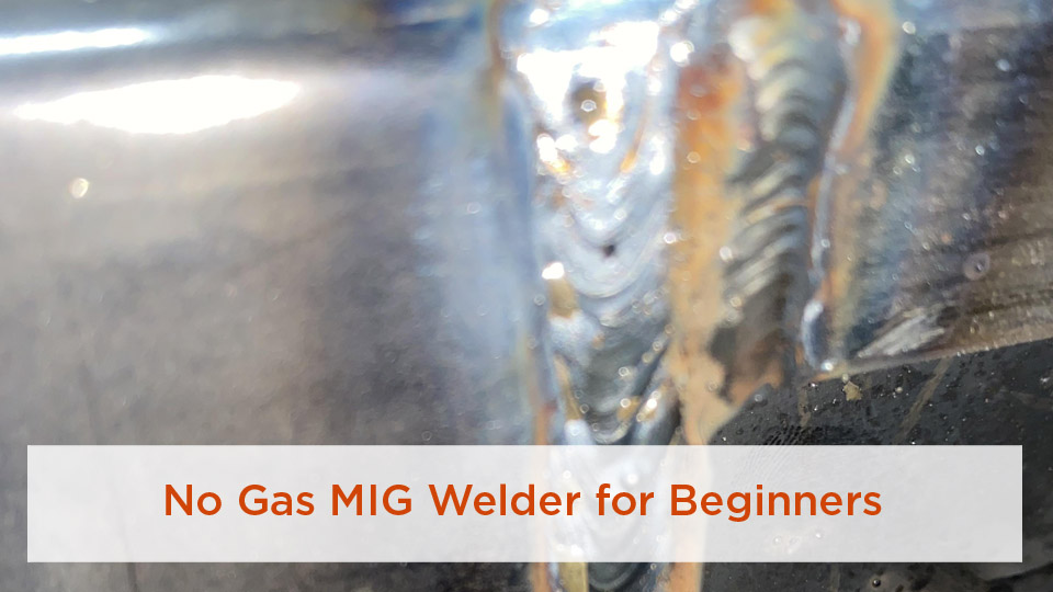
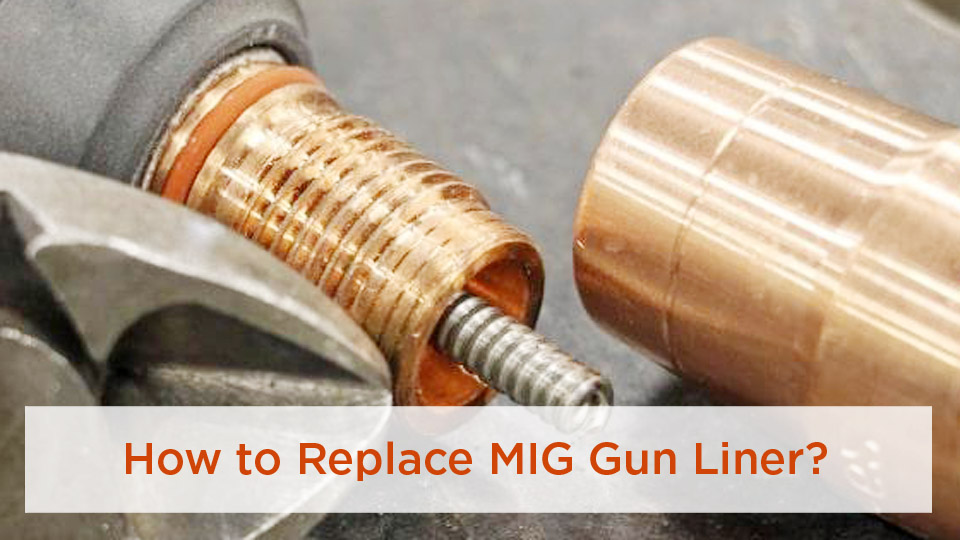
The first time I tried using gas MIG outdoors, the wind disturbed the shielding gas and left porosity in the weld. That experience showed me why many welders want to convert a gas MIG welder to gasless flux-core operation for farm repairs, gates, outdoor fabrication, and jobs where moving a cylinder is inconvenient. The conversion can be simple, but only when the welder and the selected wire support it.
Quick Answer
To convert a compatible gas MIG welder to gasless operation, install self-shielded flux-core wire, set the polarity required by that exact wire, fit the correct drive roll and contact tip, disable the gas supply, and begin with the machine chart. Test on matching scrap before welding the project.
Self-shielded flux-core can handle outdoor conditions better than gas MIG, but it does not automatically improve safety or guarantee a stronger weld. You still need correct polarity, clean metal, suitable settings, ventilation, protective equipment, and a wire that matches the machine and joint. This guide walks through the complete setup without treating one machine or wire chart as universal.
Last updated: July 19, 2026
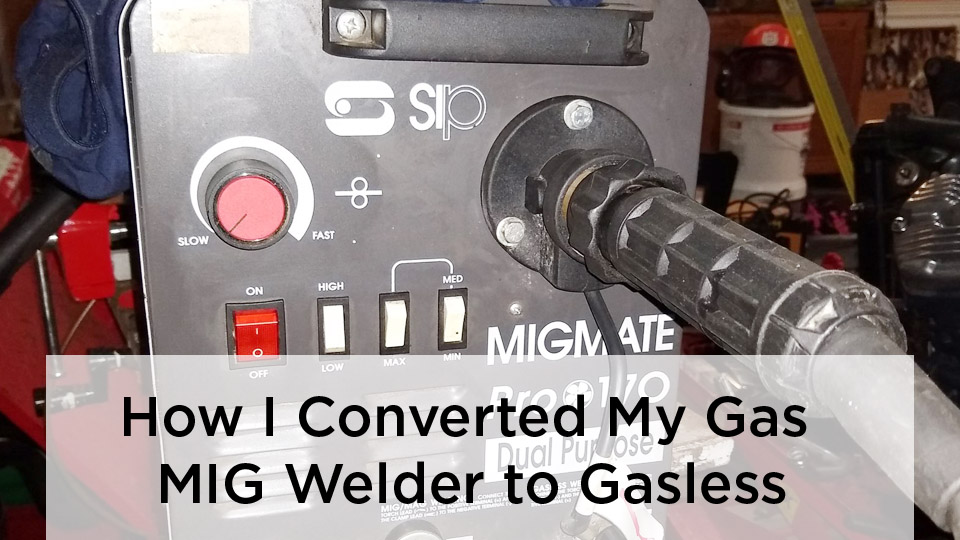
Image by mig-welding.co.uk
Key Takeaways
- Confirm that your welder supports the selected self-shielded wire diameter, polarity, spool size, and output range.
- Do not assume every gasless wire uses DCEN. Follow the polarity printed on the wire label and in the manufacturer’s data sheet.
- Use the specified drive roll, contact tip, liner, nozzle, and wire-feed tension.
- Start with the machine chart and wire data sheet, then make a test weld on matching scrap.
- Use a drag technique, control stickout, remove slag between passes, and inspect the weld before placing it in service.
- Gas MIG is usually easier to control on thin, cosmetic automotive sheet metal.
At a Glance
| Time Required | About 15 to 30 minutes for a compatible machine, plus test-weld time |
| Difficulty | Beginner to intermediate, depending on how the machine changes polarity |
| Tools Needed | Owner’s manual, self-shielded wire, correct drive roll, contact tip, hand tools, wire cutters, brush, chipping hammer, and PPE |
| Cost | Usually limited to consumables when the welder is already compatible; do not force a conversion on an incompatible machine |
What Is Gasless Welding and Why Convert?
“Gasless MIG” is the common shop term for self-shielded flux-cored arc welding, also called FCAW-S. A continuous tubular wire feeds through the gun. Compounds inside the wire react in the arc to help shield the molten weld pool, so the process does not need an external shielding-gas cylinder.
Not every flux-cored process is gasless. Gas-shielded FCAW also uses tubular wire, but it requires an external shielding gas. This guide covers self-shielded wire used with compatible constant-voltage wire-feed welders.
According to Miller’s flux-core welding guide, self-shielded FCAW is more tolerant of outdoor conditions and light surface contamination than gas MIG. It also leaves slag that must be removed, and it normally produces more cleanup than solid-wire MIG.
Converting can eliminate the need to move a cylinder and regulator to a field repair. It can also reduce problems caused by wind disturbing an external shielding-gas stream. However, strong wind can still affect the arc, spread sparks, and move fumes toward you or other people.
Note: Flux-core wire tolerates some mill scale and light rust better than gas MIG, but it is not a substitute for proper cleaning. Remove oil, grease, moisture, paint, heavy rust, and loose scale before welding.
Can Your MIG Welder Be Converted?
Do not begin by buying a random spool of flux-core wire. Begin with the welder’s owner’s manual and the label or data sheet for the wire you plan to use.
Compatibility checklist
- Process support: The manual should list self-shielded FCAW, flux-core, FCAW-S, or an approved self-shielded electrode.
- Output and polarity: Confirm that the machine can provide the polarity required by the exact wire.
- Wire diameter: Confirm that the feeder, liner, gun, contact tip, drive roll, and output range support the selected diameter.
- Spool size: Check the maximum spool diameter and weight allowed inside the machine.
- Drive-roll availability: Verify that the correct roll is installed or available for the feeder.
- Duty cycle: Make sure the machine can deliver the required output without exceeding its rated duty cycle.
- Material and joint: Confirm that the wire classification is approved for the base metal, welding position, thickness, and number of passes.
Do not assume the polarity
Many hobby-size E71T-11 self-shielded wires, including Lincoln NR-211-MP, use electrode-negative polarity, commonly written as DCEN or DC-. In that setup, the gun connects to negative and the work lead connects to positive.
That does not make DCEN a universal rule for every self-shielded electrode. The correct instruction is simple: use the polarity stated on the wire label and in the machine manual. A Miller owner’s manual, for example, tells operators to check the polarity required by the selected self-shielding wire before changing the power source.
Warning: Unplug the welder before opening a panel or moving internal polarity leads. Do not modify internal wiring, bypass interlocks, or improvise terminals. If the manual does not provide an approved polarity-change procedure, do not force the conversion.
A gas-only machine with fixed, unsuitable polarity or an unsupported feeder is not a good conversion candidate. In that case, use the machine as designed or choose a model that officially supports both solid-wire MIG and self-shielded FCAW.
Tools and Materials You’ll Need
- Welder owner’s manual: Use it for polarity, drive-roll, liner, spool, duty-cycle, and machine-setting instructions.
- Self-shielded flux-core wire: Common hobby diameters include 0.030 and 0.035 inch. Use 0.045 inch only when the feeder, gun, and power source support it.
- Correct drive roll: Tubular wire commonly uses a manufacturer-specified V-knurled roll that grips the wire without excessive pressure.
- Matching contact tip: Install the size specified for the wire diameter.
- Compatible liner: Inspect it for dirt, rust, kinks, or an incorrect internal diameter.
- Approved nozzle: Use the gun manufacturer’s flux nozzle when one is offered. Otherwise, retain the approved nozzle and insulator arrangement described in the manual.
- Hand tools: You may need a screwdriver, wrench, socket, or hex key for the drive roll and polarity terminals.
- Wire tools: Keep wire cutters and pliers nearby for trimming and feeding the electrode.
- Cleaning tools: Use a grinder where appropriate, a material-dedicated wire brush, and a chipping hammer for slag.
- Protective equipment: Use a welding helmet with an appropriate filter shade, safety glasses with side protection, flame-resistant clothing, leather gloves, suitable footwear, and hearing protection where needed.
Lincoln’s NR-211-MP product information lists 0.030-, 0.035-, and 0.045-inch versions. That does not mean every welder can run every listed diameter. The machine manual and wire data must agree.
Pro Tip: Too much drive-roll pressure can flatten tubular wire and cause feeding problems. Use only enough tension to feed the wire without slipping, following the feeder’s adjustment procedure.
Products Worth Considering

E71T-GS FLUX CORE WIRE: This self-shielding, AWS E71T-GS flux-cored wire excels due to its advanced core design, delivering exceptional arc stabilization and high feedability for effortless welding. The core also incorporates powerful deoxidizing agents, ensuring clean, reliable welds even when welding through light rust or mill scale.

E71T-GS GASLESS FLUX CORE WIRE: This AWS E71T-GS self-shielded flux-cored wire delivers smooth, stable welding without external shielding gas. It offers excellent arc stability, consistent feedability and reliable performance, allowing users to produce clean welds with minimal setup work. Its advanced flux formulation enables welding over light rust and mill scale for improved everyday practicality.

E71T-GS FLUX CORE WIRE: This self-shielding, AWS E71T-GS flux-cored wire excels due to its advanced core design, delivering exceptional arc stabilization and high feedability for effortless welding. The core also incorporates powerful deoxidizing agents, ensuring clean, reliable welds even when welding through light rust or mill scale.
Step-by-Step Guide to Converting Your MIG Welder
1. Read the machine and wire instructions
Locate the machine’s FCAW setup section, polarity diagram, wire chart, and duty-cycle rating. Then read the wire label or technical data sheet. Confirm the required polarity, diameter, contact-tip-to-work distance, voltage range, wire-feed range, welding positions, and thickness limits.
2. Power down and unplug the welder
Turn the machine off, unplug it, and wait as directed by the manufacturer before touching internal terminals. Electrical shock is not a normal part of setup. Keep the gun trigger protected so it cannot be pressed accidentally while you work.
3. Shut down the gas supply safely
Close the cylinder valve. Follow the regulator and welder instructions for relieving trapped pressure. If you are removing the cylinder from the cart, disconnect it safely, install the protective valve cap when required, and store it upright in a secured, ventilated location away from heat and damage.
You usually do not need to remove every gas hose from the machine just to run self-shielded wire. The important points are that the gas is shut off, the cylinder is secure, and the welder is configured as its manual directs.
4. Set the required polarity
Use the diagram inside the machine or in the manual. For a wire that specifies DCEN, connect the gun lead to the negative terminal and the work lead to the positive terminal. For a wire that specifies a different polarity, follow that wire’s instructions instead.
Tighten the approved terminals securely, replace all covers, and never operate the machine with an internal panel left open.
5. Install the correct drive roll
Install the roll and groove specified for the wire type and diameter. Many tubular wires use a V-knurled groove. Make sure the groove aligns with the inlet guide and gun liner.
Set spool-hub tension only high enough to prevent the spool from coasting after the trigger is released. Excessive brake tension can overload the feeder, while too little tension can let the spool unravel.
6. Load the flux-core wire
Wear gloves because cut wire ends are sharp. Keep control of the wire when releasing it from the spool. Trim off the bent end and feed a straight section through the inlet guide and drive roll.
Keep the gun cable as straight as practical. Many machines feed more easily when the contact tip is temporarily removed, but follow the manual’s exact loading procedure. Jog the wire until it exits the gun, then switch the machine off before installing the matching contact tip.
7. Install the contact tip and approved nozzle
Fit a clean contact tip that matches the wire diameter. Install the manufacturer-approved flux nozzle when available. A narrow flux nozzle can improve puddle visibility and reduce the area that collects spatter.
Do not remove required insulators, diffusers, or protective gun parts. A bare or incorrectly assembled gun can expose components to damage and may create an electrical hazard.
8. Prepare the joint and work-clamp area
Remove oil, grease, moisture, paint, loose scale, and heavy rust. Clean a separate spot for the work clamp so the circuit has solid metal-to-metal contact.
For thicker butt joints, edge preparation may be necessary. Miller recommends considering a bevel when material is over 1/4 inch so the joint can achieve suitable fusion. The correct bevel, root opening, number of passes, and weld size still depend on the design and procedure.
Warning: Do not weld over paint, solvent residue, unknown coatings, plating, or galvanized surfaces until you have identified and controlled the fume hazard. Never weld inside an unventilated confined space or on a closed container that held a flammable or unknown substance.
9. Enter the starting settings
Use the chart inside the welder or the manufacturer’s calculator for the selected wire diameter, material thickness, joint, and position. If the machine has a process selector, choose the approved FCAW or flux-core mode.
Do not copy settings from a different wire simply because the diameters match. Flux formulation, polarity, contact-tip-to-work distance, power-source design, and feeder calibration all affect the usable range.
10. Make a test weld
Use scrap with the same material type, thickness, joint style, position, and surface preparation as the project. Attach the work clamp to clean metal. Run a short bead and observe arc stability, bead shape, slag behavior, spatter, fusion at the toes, and any visible porosity.
Change one control at a time in small steps. Record the final voltage and wire-feed settings when the test produces a stable bead.
The wire label, technical data sheet, and welder chart outrank any generic settings table.
Choosing Flux-Core Wire and Metal Thickness
Wire diameter is only one part of electrode selection. Check the complete classification, approved polarity, welding positions, mechanical properties, pass limitations, and thickness range.
- 0.030-inch wire: Often suitable for lower-output machines and a useful range of light fabrication, depending on the product.
- 0.035-inch wire: A common general-purpose size when the welder has enough output and the feeder supports it.
- 0.045-inch wire: Requires a compatible liner, contact tip, drive roll, feeder, and power source. It should not automatically be treated as a 3/8-inch-and-thicker solution.
For example, Lincoln’s NR-211-MP technical data sheet lists a maximum plate thickness of 5/16 inch for its 0.030-, 0.035-, and 0.045-inch diameters. That limit is product-specific. Another electrode may have different restrictions.
Products Worth Considering

Welding Easy and Quick: AWS E71T-GS 030” Flux Core welding wire (The actual Net Weight of Wire is 2LB), no need for shielding gas, install it then you can welding all positions, single and multi pass welding. Great for T-joints, butt welds & lap welds.

【Easy and Fast Welding】This flux core wire (E71T-GS, actual net weight 2 lbs) requires no shielding gas – just install and start welding. It performs well in all positions and supports both single‑pass and multi‑pass welding, making it ideal for quick repairs on farm equipment, fence posts, or automotive bodywork, even outdoors on windy days.

Effortless and Efficient Welding: Hassle-free experience with our AWS E71T-GS 0.030" Flux Core welding wire (Net Weight: 10lbs). No shielding gas needed, install and weld in any position. Perfect for strong T-joints, butt welds, and lap welds.
What about car panels?
Self-shielded wire can be difficult to control on thin automotive sheet because it creates slag, spatter, and concentrated heat. For clean body-panel work, gas MIG with suitable small-diameter solid wire is usually easier to tack, stitch, and finish without burn-through or excessive distortion.
If you must use self-shielded wire on thin material, confirm that the wire and machine chart support the thickness. Practice on matching scrap, use short welds with cooling time, and avoid treating a cosmetic panel repair like a heavy farm-equipment joint.
Machine Settings for Gasless Welding
Voltage and wire-feed speed work together. The required combination depends on the wire, diameter, stickout, material thickness, joint, position, and machine.
The original idea of using fixed values such as 80 to 110 amps for every 0.030-inch wire or 150 to 200 amps for every 0.045-inch wire is too broad. Even products from the same manufacturer can use different operating windows.
Use the chart as a starting point
- Choose the exact wire type and diameter on the machine chart.
- Select the material thickness and welding position.
- Set the recommended voltage or voltage tap.
- Set the recommended wire-feed speed.
- Set the contact-tip-to-work distance specified by the wire manufacturer.
- Test on matching scrap and make one small adjustment at a time.
Control stickout
Self-shielded flux-core normally uses a longer stickout than short-circuit MIG. Miller gives approximately 3/4 inch as a general FCAW starting point. Lincoln’s NR-211-MP data lists approximately 1/2 inch for 0.030 inch, 1/2 to 5/8 inch for 0.035 inch, and 5/8 inch for 0.045 inch.
Use the distance specified for your wire. An inconsistent stickout changes current and can make the arc unstable even when the machine controls have not moved.
Read the arc and bead
- Wire repeatedly stubs into the plate: Check for excessive wire speed, insufficient voltage, poor work-clamp contact, excessive drive tension, liner restriction, or an overly long and unstable stickout.
- Arc is long, harsh, or creates heavy spatter: Check for excessive voltage, insufficient wire feed, wrong polarity, or excessive gun angle.
- Bead sits high with poor toe fusion: Check heat input, travel speed, joint preparation, work angle, and whether the machine is large enough for the joint.
- Burn-through: Reduce heat input within the approved range, increase travel speed, shorten weld length, improve fit-up, or switch to a more suitable process for the thin material.
Flux-Core Welding Technique After the Conversion
Drag the gun
For common slag-producing flux-core welding, point the gun back toward the weld pool and drag it along the joint. Miller summarizes the technique as “if there’s slag, you drag.” A normal travel angle is about 5 to 15 degrees. Excessive angle can increase spatter and reduce penetration.
Use the correct work angle
- Butt joint: Center the gun between both pieces.
- T-joint: Begin near a 45-degree work angle so heat is shared between the pieces.
- Lap joint: Direct more heat toward the lower or thicker member as the joint requires.
Control travel speed
Moving too slowly can create an oversized bead, excessive heat, burn-through, or slag problems. Moving too quickly can create a narrow bead, undercut, poor fusion, or incomplete fill. Watch the puddle edges rather than chasing only the arc light.
Remove slag between passes
Allow the weld to cool as the procedure requires. Wear safety glasses, chip the slag, and brush the bead until the surface and toes are visible. Do not place another pass over loose slag.
Pros and Cons of Gasless Welding
Self-shielded FCAW is useful when its strengths match the job, but it does not replace gas MIG in every situation.
| Aspect | Advantages | Tradeoffs |
|---|---|---|
| Gas equipment | No external shielding-gas cylinder is required for self-shielded wire | The wire usually costs more than comparable solid wire |
| Portability | Easier to move into yards, fields, and remote repair areas | The machine, cables, fire controls, and ventilation needs still travel with you |
| Outdoor use | More tolerant of wind than gas MIG | Strong wind can still affect the arc, spread sparks, and move fumes |
| Surface condition | More tolerant of light rust and mill scale than gas MIG | Oil, paint, moisture, heavy rust, and hazardous coatings still require removal or control |
| Weld appearance | Can provide useful penetration and deposition on suitable fabrication work | Produces slag and commonly more spatter and cleanup than solid-wire MIG |
| Thin material | Some wires and machines support light-gauge material | Gas MIG is usually easier to control on thin cosmetic sheet metal |
Common Mistakes and How to Fix Them
| Problem | Likely causes | What to check |
|---|---|---|
| Erratic or sputtering arc | Wrong polarity, unstable wire feed, poor work connection, or unsuitable settings | Wire label, polarity leads, clamp area, drive roll, liner, tip, voltage, and wire speed |
| Porosity | Moisture, contamination, excessive wind, incorrect stickout, damaged wire, or poor technique | Clean and dry the joint, protect the arc, inspect the spool, and verify wire-specific parameters |
| Heavy spatter | Wrong polarity, poor voltage-to-wire-speed balance, excessive angle, or feeding variation | Return to chart settings, correct the angle, and stabilize the feeder |
| Bird’s nest near the feeder | Blocked liner, incorrect tip, excessive roll pressure, crossed groove, or kinked gun cable | Stop immediately, cut out damaged wire, inspect the complete feed path, and reset tension |
| Slag inclusions | Slag left between passes, poor angle, low heat input, narrow joint, or poor bead placement | Clean every pass, correct the joint preparation, and direct the arc into both toes |
| Lack of fusion | Travel too fast, unsuitable settings, poor work angle, dirty joint, or insufficient machine capacity | Clean and prepare the joint, verify parameters, and confirm that the machine and wire suit the thickness |
| Burn-through | Too much heat, slow travel, poor fit-up, or material below the practical range | Use short welds, improve fit-up, reduce heat within the approved range, or use gas MIG |
A polarity mistake can waste a great deal of troubleshooting time. So can a smooth or incorrectly aligned drive roll that lets the wire slip. Before changing several machine settings, return to the basic setup and verify each component in order.
Safety Considerations for Gasless Welding
Protect your eyes and skin
Wear a welding helmet with a filter shade appropriate for the actual current. OSHA’s eye-protection guidance for GMAW and FCAW lists minimum shade 7 below 60 amps and minimum shade 10 from 60 through 500 amps, with darker ANSI and AWS recommendations at higher currents.
Wear safety glasses with side protection under the helmet. They remain important when you lift the helmet to chip slag, brush the bead, or grind the joint.
Control fumes
Self-shielded flux-core welding creates a visible fume plume. Work so the plume moves away from your breathing zone. Outdoor work does not automatically guarantee adequate ventilation.
OSHA’s welding-fume guidance recommends local exhaust or suitable general ventilation when needed. Respiratory protection may be required when work practices and ventilation cannot control exposure.
Prevent fires
Remove combustibles from the work area. Check the opposite side of walls, floors, panels, and equipment for hidden material that can ignite. Keep suitable fire-extinguishing equipment available and continue checking the area after welding when sparks or hot metal could have traveled out of sight.
Protect the electrical circuit
Inspect the gun, work lead, cables, plug, and insulation before use. Keep gloves and clothing dry. Place the work clamp on clean metal as close to the joint as practical without interfering with the weld.
Know when the job requires a qualified procedure
Do not use a general conversion guide as the welding procedure for a load-bearing structure, trailer coupling, suspension part, lifting device, pressure-containing item, roll cage, critical vehicle repair, or other life-safety joint.
AWS D1.1/D1.1M:2025-AMD1 covers qualification, fabrication, inspection, and acceptance requirements for structural steel. A project may also be governed by another code, contract specification, engineer-approved procedure, or local requirement.
Real-World Applications: Gasless Welding in Action
Self-shielded flux-core is especially useful when portability and outdoor wind tolerance matter.
- DIY projects: Gates, workbenches, racks, and grills made from compatible mild-steel thicknesses.
- Field repairs: Farm equipment, fences, and noncritical machinery repairs where a gas cylinder is inconvenient.
- Shop fabrication: General mild-steel work where slag cleanup and spatter are acceptable.
- Training: Practice with wire feeding, travel angle, joint preparation, and slag removal under qualified supervision.
A windy boat-trailer or farm repair is the type of situation that makes self-shielded wire attractive. However, a trailer repair can affect road safety. Inspect the base metal for thinning and cracking, confirm the joint design, and use a qualified repair procedure when the component is structural or safety-critical.
How to Convert Back to Gas MIG
- Turn the welder off, unplug it, and close the cylinder valve.
- Remove the self-shielded wire while keeping control of the spool end.
- Set the polarity required by the selected solid wire and shielding gas. Many common steel MIG setups use DCEP, but follow the machine chart.
- Install the correct smooth or specified solid-wire drive-roll groove.
- Confirm that the liner and contact tip match the solid-wire diameter.
- Reinstall the approved gas nozzle and check the diffuser and O-rings.
- Reconnect and secure the regulator and gas hose as the manufacturer directs.
- Open the cylinder valve correctly, check for leaks using an approved method, and set the recommended flow rate.
- Enter the machine-chart settings and make a test weld on matching scrap.
Conclusion: Weld with Confidence, Gas or No Gas
Converting a compatible gas MIG welder to self-shielded flux-core operation can make outdoor repairs and portable fabrication easier. The reliable sequence is to identify the exact wire, confirm machine compatibility, set the wire’s required polarity, install the correct feed components, shut down the gas supply, prepare the joint, and begin with documented settings.
The conversion does not make every welder suitable for every thickness. It also does not replace cleaning, ventilation, PPE, correct technique, or inspection. Flux-core is useful for gates, farm repairs, racks, and other suitable steel work, while gas MIG often remains the cleaner choice for thin sheet and cosmetic automotive panels.
Keep spare contact tips only when your setup genuinely needs them, but focus first on clean wire, stable feeding, correct stickout, and the manufacturer’s operating range. Make a test weld, remove the slag, inspect the bead, and do not place a critical joint in service unless it meets the applicable procedure and inspection requirements.
Frequently Asked Questions
Can any MIG welder be converted to gasless?
No. The welder must support self-shielded flux-core wire, the required polarity, the selected diameter, the correct drive roll, and enough output for the joint. Check the owner’s manual before buying wire or moving internal leads.
Does gasless flux-core wire always use DCEN?
No universal polarity rule should replace the wire instructions. Many common E71T-11 self-shielded wires use DCEN, but you must follow the polarity printed on the selected electrode and in the welder manual.
What is the difference between gas MIG and gasless flux-core welding?
Gas MIG normally uses solid wire and an external shielding gas. Self-shielded FCAW uses tubular wire whose internal compounds help protect the weld pool. FCAW is more tolerant of outdoor wind, but it leaves slag and usually requires more cleanup.
Why are my gasless welds full of spatter?
Check the wire’s polarity, machine-chart settings, work-clamp connection, drive-roll tension, liner, contact tip, stickout, travel angle, and wire condition. Return to the documented starting settings and change only one control at a time.
Is gasless welding stronger than gas MIG?
Not automatically. Either process can make an acceptable weld when the consumable, base metal, joint design, settings, technique, and inspection are correct. A defective flux-core weld is not stronger simply because the process can provide deep penetration.
Can I use gasless flux-core wire on car body panels?
Some machines and wires can weld light-gauge steel, but self-shielded wire is harder to control on thin cosmetic panels. Gas MIG is usually the better choice because it produces less slag and makes short tacks and heat control easier.
How do I clean slag from gasless welds?
Wear safety glasses, allow the weld to cool as required, break the slag with a chipping hammer, and finish with a clean wire brush dedicated to the base material. Remove all loose slag before another pass. Keep anti-spatter products out of the weld joint and use them only according to their labels.
Sources
- Miller: Flux-Cored Welding Basics for Mild Steel — process differences, setup, cleaning, stickout, settings, and gun technique
- Lincoln Electric: Innershield NR-211-MP — wire classification and product information
- Lincoln Electric: NR-211-MP Technical Data Sheet — polarity, thickness limits, stickout, voltage, current, and wire-feed ranges
- OSHA: Controlling Hazardous Fume and Gases During Welding — ventilation, coatings, confined spaces, and respiratory protection
- OSHA: Eye Protection During Welding — filter-shade selection and primary eye protection
- American Welding Society: AWS D1.1/D1.1M:2025-AMD1 — structural-steel procedure, qualification, fabrication, inspection, and acceptance requirements