Flux core welding settings are not one-size-fits-all. Your wire classification, diameter, welder output, joint design, position, and metal thickness all change the correct voltage and wire feed speed. The safest approach is to start with the chart inside your machine and the wire manufacturer’s data sheet, then test on scrap that matches the job.
Last updated: July 20, 2026.
Quick Answer
Use your welder’s door chart and the exact wire data sheet first. For many common .030- and .035-inch self-shielded mild-steel wires, start with DCEN polarity, about 1/2 to 3/4 inch of contact-tip-to-work distance, and a 5- to 15-degree drag angle. Test on matching scrap, then tune voltage and wire speed together.
Key Takeaways
- The machine chart and wire data sheet override any generic flux core settings chart.
- Check polarity on the wire label. Many self-shielded wires use DCEN, while gas-shielded flux core commonly uses DCEP.
- Wire feed speed mainly controls current; voltage controls arc length and bead width.
- Keep a steady contact-tip-to-work distance and use a drag technique when the wire creates slag.
- Clean the weld zone, test on scrap, and never treat a generic chart as proof of code compliance.
At a Glance
| Time Required | 20–40 minutes for setup, scrap testing, and final adjustment |
| Difficulty | Beginner to intermediate |
| Tools Needed | Flux-capable wire welder, correct wire and drive roll, contact tip, work clamp, grinder or wire brush, chipping hammer, clamps, scrap steel, helmet, gloves, and protective clothing |
| Cost | Low when you already own the welder and safety gear; the main ongoing costs are wire, tips, abrasives, and electricity |
What Is Flux Core MIG Welding?
“Flux core MIG” is a common shop term, but the formal process name is flux-cored arc welding, or FCAW. The electrode is a hollow wire filled with flux. That flux supports the arc, helps clean the puddle, and forms slag over the weld as it cools.
There are two main versions:
- Self-shielded flux core (FCAW-S): The wire provides its own shielding system, so you do not connect an external gas cylinder. This makes it useful for outdoor fabrication, field repairs, and portable work.
- Gas-shielded flux core (FCAW-G): The tubular wire also needs an external shielding gas. It is common in production welding where high deposition rates, smooth arc characteristics, and code-qualified procedures matter.
Self-shielded flux core handles light wind better than gas MIG, but it is not a license to weld over paint, oil, heavy rust, or thick mill scale. Clean steel still gives you a more stable arc and a lower risk of porosity, slag inclusions, and lack of fusion. Miller’s flux-cored welding guide also recommends cleaning the base metal and the work-clamp area before welding.
Note: This guide focuses on common carbon-steel self-shielded wire. Stainless steel, low-alloy steel, cast iron, and aluminum require different filler metals and procedures.
How to Read a Flux Core Welding Settings Chart
A useful chart connects five variables: wire classification, wire diameter, voltage, wire feed speed, and contact-tip-to-work distance. Material thickness matters, but the same thickness may need different settings for a lap joint, fillet, square butt joint, beveled groove, vertical weld, or overhead weld.
Why Your Machine Chart Comes First
Two welders can use different dial numbers even when they deliver similar output. One machine may show actual volts and inches per minute, while another uses numbered voltage taps and a 1–10 wire-speed scale. Do not copy knob positions from another model. Use the chart inside your own welder, the owner’s manual, and the exact wire data sheet.
For example, Forney’s 210 MIG setup chart gives different tap and feed settings for .030-, .035-, and .045-inch E71T-GS wire across 18-gauge through 1/4-inch steel. It also leaves the 20- and 22-gauge cells blank for that wire, which shows why a generic “one setting fits all” table can be misleading. See the manufacturer’s 210 MIG setup chart.
What Each Control Changes
- Wire feed speed: On a constant-voltage wire welder, increasing wire speed generally increases welding current and deposition rate. Too much feed for the selected voltage makes the wire drive into the work.
- Voltage: Voltage changes arc length, bead width, and bead profile. Too little can create a harsh, stubbing arc. Too much can create excessive spatter, undercut, or gas marks.
- Contact-tip-to-work distance: Also called CTWD, this is the distance from the contact tip to the work. Keep it consistent because changing it changes current and arc behavior.
- Travel speed: Moving too fast can produce a narrow bead with poor fusion. Moving too slowly can create excessive buildup, a wide heat-affected zone, or burn-through on thin steel.
- Gun angle: When the wire creates slag, use a drag technique. A travel angle of about 5–15 degrees is a reliable starting point.
Verified Flux Core Settings Chart for a Common E71T-11 Wire
The table below uses Lincoln Electric’s published operating window for Innershield NR-211-MP E71T-11. It is an example for that product, not a universal chart for every E71T-11 or E71T-GS wire.
| Wire Diameter | Polarity | CTWD | Wire Feed Speed | Voltage Range | Approx. Current | Published Maximum Plate Thickness |
|---|---|---|---|---|---|---|
| .030 in | DCEN | 1/2 in | 50–300 IPM | 13–19 V | 30–140 A | 5/16 in |
| .035 in | DCEN | 1/2–5/8 in | 50–275 IPM | 14–21 V | 30–155 A | 5/16 in |
| .045 in | DCEN | 5/8 in | 70–130 IPM | 15–19 V | 120–170 A | 5/16 in |
| .068 in | DCEN | 3/4–1 1/4 in | 40–175 IPM | 15–24 V | 125–300 A | 1/2 in |
Warning: Do not extrapolate the .030- or .035-inch rows to 1/2-inch structural work. The example data sheet limits those diameters to 5/16-inch plate. Thick, load-bearing, lifting, pressure, or structural welds need the correct consumable, machine capacity, joint design, qualified procedure, and inspection.
Products Worth Considering

E71T-GS FLUX CORE WIRE: This self-shielding, AWS E71T-GS flux-cored wire excels due to its advanced core design, delivering exceptional arc stabilization and high feedability for effortless welding. The core also incorporates powerful deoxidizing agents, ensuring clean, reliable welds even when welding through light rust or mill scale.

Welding Easy and Quick: AWS E71T-GS 030” Flux Core welding wire (The actual Net Weight of Wire is 2LB), no need for shielding gas, install it then you can welding all positions, single and multi pass welding. Great for T-joints, butt welds & lap welds.

E71T-GS FLUX CORE WIRE: This self-shielding, AWS E71T-GS flux-cored wire excels due to its advanced core design, delivering exceptional arc stabilization and high feedability for effortless welding. The core also incorporates powerful deoxidizing agents, ensuring clean, reliable welds even when welding through light rust or mill scale.
Practical Starting Zone by Mild-Steel Thickness
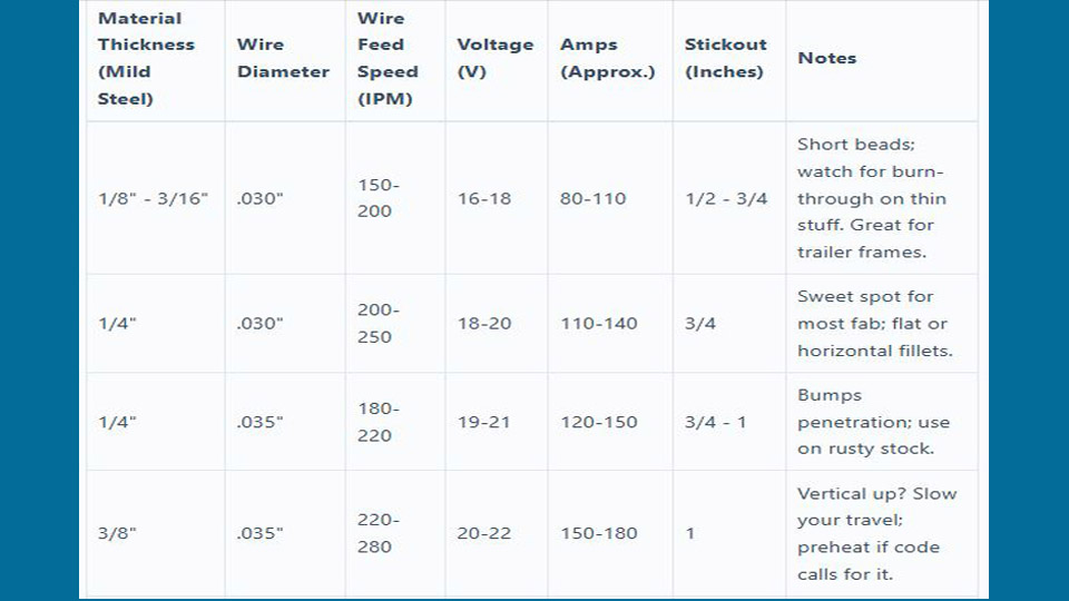
Use this table to choose a part of the manufacturer’s operating range. Then test and adjust. It intentionally avoids fake precision because the correct number depends on your machine and wire.
| Steel Thickness | Common Wire Choice | Starting Zone | Technique and Joint Notes |
|---|---|---|---|
| 18–16 gauge | .030 in | Lower end of the wire maker’s range | Use short tacks or stitch welds, keep gaps tight, and allow cooling time. Gas MIG is often easier on cosmetic body panels. |
| 1/8 in | .030 in | Lower-middle range | Run a short test bead. Watch the back side for excessive penetration or burn-through. |
| 3/16 in | .030 or .035 in | Middle range | Clean the joint and hold a steady CTWD. A small weave may help fill a wider fillet, but do not outrun the puddle. |
| 1/4 in | .035 in | Middle-upper range | Bevel butt joints when needed for fusion. Multi-pass welding may be required depending on the joint and machine output. |
| 5/16 in | .035 or .045 in | Upper range, only within the data sheet | Confirm duty cycle, joint preparation, pass sequence, and wire approval before welding. |
| Over 5/16 in | Product- and machine-specific | Do not guess from a hobby chart | Use a wire and procedure rated for the thickness. Larger self-shielded wire or gas-shielded flux core may be appropriate. |
Pro Tip: Keep a settings log with the wire brand, classification, diameter, polarity, voltage, wire speed, CTWD, position, joint type, and steel thickness. Your own verified notes become more useful than a generic chart.
How to Choose the Right Flux Core Wire
Wire diameter matters, but the AWS classification and product data sheet matter more. Similar-looking spools may have different polarity, shielding, pass limits, mechanical properties, and approved positions.
Products Worth Considering
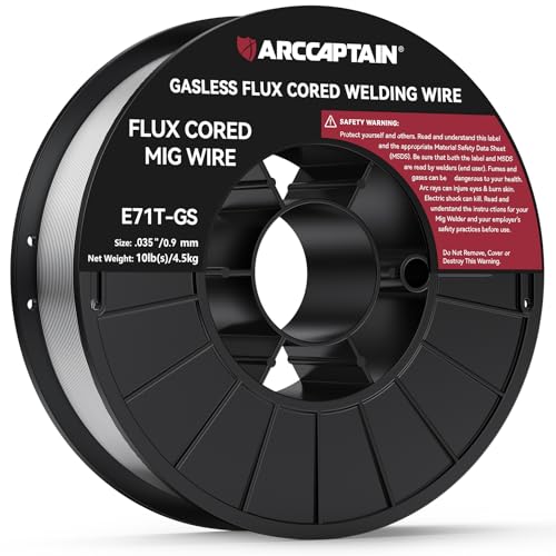
Effortless and Efficient Welding: Hassle-free experience with our AWS E71T-GS 0.035" Flux Core welding wire (Net Weight: 10lbs). No shielding gas needed, install and weld in any position. Perfect for strong T-joints, butt welds, and lap welds.

E71T-GS FLUX CORE WIRE: This self-shielding, AWS E71T-GS flux-cored wire excels due to its advanced core design, delivering exceptional arc stabilization and high feedability for effortless welding. The core also incorporates powerful deoxidizing agents, ensuring clean, reliable welds even when welding through light rust or mill scale.

E71T-GS FLUX CORE WIRE: This self-shielding, AWS E71T-GS flux-cored wire excels due to its advanced core design, delivering exceptional arc stabilization and high feedability for effortless welding. The core also incorporates powerful deoxidizing agents, ensuring clean, reliable welds even when welding through light rust or mill scale.
E71T-GS
E71T-GS is common in small consumer machines and general repair work. Many products are designed for single-pass welding, and capabilities vary by manufacturer. Do not assume every E71T-GS spool is suitable for multi-pass or structural work.
E71T-11
E71T-11 is a common all-position self-shielded classification. Specific products such as NR-211-MP allow multiple passes within published limits, but the product data sheet still controls maximum thickness, polarity, CTWD, and operating range. Hobart’s Fabshield 21B is another E71T-11 example.
Gas-Shielded Flux Core
Gas-shielded wires such as E71T-1 products are common in indoor fabrication. They may use carbon dioxide or an argon/carbon-dioxide blend, depending on the exact classification and product. Never choose gas by habit; use the data sheet.
Wire Diameter
- .030 inch: A practical choice for lower-output machines and thinner mild steel.
- .035 inch: A common general-fabrication size when the welder has enough output.
- .045 inch and larger: Better suited to higher-output equipment and heavier work, but only when the feeder, gun, liner, drive rolls, and power source support the wire.
Store wire in a clean, dry place and keep it sealed when possible. If a spool becomes rusty, visibly damaged, or moisture-contaminated, replace it unless the manufacturer gives a specific recovery procedure. Do not bake a consumer spool at an improvised temperature.
Step-by-Step: Set Up a MIG Welder for Self-Shielded Flux Core
- Read the labels. Confirm the machine can run the wire diameter and process. Read the wire classification, polarity, CTWD, and pass limitations.
- Disconnect input power before changing internal connections. Follow the owner’s manual when moving polarity leads or changing drive rolls.
- Set the correct polarity. Many common self-shielded mild-steel wires use DCEN, with the gun negative and work lead positive. This is not universal, so follow the spool and data sheet.
- Install the correct drive roll. Tubular wire normally feeds best with the machine maker’s recommended knurled or V-knurled groove. Match the groove to the wire diameter.
- Fit the correct contact tip. Use a tip marked for the wire diameter. A gasless nozzle is optional on many guns; it can improve visibility, but do not remove the diffuser or other required gun parts.
- Set spool-brake and drive-roll tension. Use only enough tension to feed smoothly. Excessive pressure can deform tubular wire and contribute to birdnesting.
- Prepare the work and clamp. Remove oil, paint, heavy rust, moisture, and coatings from the weld zone. Attach the work clamp to clean metal close to the joint.
- Prepare the joint. Tight fit-up helps thin steel. Bevel thicker butt joints when the joint design requires it. Tack spacing depends on thickness, distortion risk, and part geometry, not a fixed three-inch rule.
- Dial in the starting settings. Use your machine chart and wire data sheet. Set the recommended CTWD before judging the arc.
- Run a test coupon. Use scrap with the same thickness, joint type, and position. Adjust one control at a time and inspect the bead before welding the actual part.
If you also use solid wire, this separate guide explains how to set up a MIG welder with gas.
How to Fine-Tune Voltage and Wire Feed Speed
Start in the recommended range, keep the gun angle and CTWD steady, and make a short bead. Then use the symptoms below to decide what to change.
| Symptom | Likely Causes | What to Check or Change |
|---|---|---|
| Wire stubs into the plate | Too much wire speed for the selected voltage, low voltage, or poor electrical connection | Increase voltage slightly or reduce wire speed; inspect the work clamp and cable connections. |
| Wire burns back to the tip | Wire speed too low, voltage too high, short CTWD, or restricted wire feeding | Increase wire speed or reduce voltage; inspect the tip, liner, drive roll, and spool tension. |
| Heavy spatter | Wrong polarity, voltage/feed mismatch, excessive travel angle, contamination, or inconsistent CTWD | Verify polarity first, then return to the chart and make small adjustments. |
| Worm tracks or gas marks | Excessive voltage, long arc, moisture, contamination, or trapped gas | Reduce voltage within the data-sheet range, hold the specified CTWD, clean the joint, and replace suspect wire. |
| Porosity | Oil, paint, moisture, heavy rust, damaged wire, or poor technique | Stop and remove the defective weld. Clean to sound metal and correct the source before rewelding. |
| Ropey bead with poor toe fusion | Low heat, fast travel, wrong work angle, or inadequate joint preparation | Increase output within limits, slow slightly, direct the arc into both toes, or improve the bevel and fit-up. |
| Burn-through | Excessive heat input, slow travel, large gap, or thin material | Lower the setting, use shorter welds, tighten the fit-up, and let the panel cool between tacks. |
| Slag inclusion | Welding over slag, poor angle, oversized weave, or low heat | Clean every pass, narrow the weave, correct the angle, and confirm fusion at the toes. |
Step-by-Step: Run Your First Flux Core Weld
A lap joint on clean 1/8-inch mild steel is a practical first exercise. It is thick enough to reduce instant burn-through but still works with many small flux-capable welders.
- Cut two matching coupons and remove mill scale, paint, oil, and rust from the weld area.
- Overlap the pieces by about one inch and clamp them flat. Add small tacks at the ends.
- Set polarity, wire speed, voltage, and CTWD from your machine chart and wire data sheet.
- Place the work clamp on clean steel close to the joint.
- Hold the gun at the correct work angle for the lap joint, then use a 5- to 15-degree drag angle.
- Start the arc and watch the leading edge of the puddle. Move steadily enough to keep the bead uniform without outrunning fusion at the toes.
- Fill the end crater before releasing the trigger.
- Let the coupon cool, chip the slag, and wire-brush the bead.
- Inspect for cracks, porosity, undercut, overlap, slag lines, and poor tie-in. Cut and bend a practice coupon when you need a better view of fusion.
Note: A hammer test can expose an obviously weak practice weld, but it does not prove code compliance or confirm internal fusion. Critical work needs the inspection and testing required by the applicable procedure or standard.
Gun Angles and Settings for Different Positions
Flat Butt Joint
Hold a 90-degree work angle so the wire points into the center of the joint. Use a 5- to 15-degree drag angle. Keep the motion straight unless a small weave is needed for a wider prepared groove.
T-Joint Fillet
Start near a 45-degree work angle so heat is shared between both pieces. Adjust slightly toward the thicker member when the parts are not the same thickness.
Lap Joint
A work angle around 60–70 degrees can direct more heat into the lower plate. Keep the arc near the leading edge of the puddle and confirm fusion at the upper toe.
Vertical Welding
Vertical welding fights gravity. Miller recommends reducing voltage and amperage about 10–15 percent from the flat-position starting point, then testing. Vertical down can help control burn-through on thin steel, while vertical up generally gives better penetration on thicker steel. Keep the weave narrow and clean slag between passes.
Overhead Welding
Use the wire maker’s approved position, a compact puddle, a steady CTWD, and settings near the lower end of the acceptable range. Wear full protective clothing because sparks and slag fall directly toward you.
Flux Core vs Gas MIG
| Factor | Self-Shielded Flux Core | Gas MIG With Solid Wire |
|---|---|---|
| Shielding | Generated by the wire’s flux system; no cylinder required | External shielding gas is required |
| Outdoor use | More tolerant of light wind | Needs protection from drafts that can disrupt shielding |
| Thin sheet | Possible with the right machine and wire, but harder to control on very thin panels | Usually easier for thin, cosmetic sheet-metal work |
| Surface condition | More tolerant of light scale or contamination, but cleaning is still required | More sensitive to contamination |
| Cleanup | Produces slag, more smoke, and often more spatter | No slag and usually less cleanup |
| Heavy fabrication | Can provide strong penetration and high deposition with the correct wire and equipment | Capable, but output and transfer mode may limit deposition on smaller machines |
| Metal options | Requires a flux-cored wire made for the exact alloy | Can weld carbon steel, stainless, or aluminum with the correct wire, gas, feeding system, and machine setup |
| Code work | Acceptable only when the filler, procedure, welder qualification, and inspection meet the applicable requirements | The same rule applies; process choice alone does not make a weld code-compliant |
For aluminum, shop GMAW normally uses an aluminum wire, 100 percent argon, and a suitable spool gun or push-pull feeding system. A stainless tri-mix is not the standard shielding choice for aluminum.
Essential Flux Core Welding Safety
Warning: Welding creates intense light, hot metal, sparks, electric-shock hazards, and hazardous fumes. Do not weld in a confined or enclosed space without the required training, ventilation, monitoring, and rescue controls.
- Helmet and eye protection: Wear a welding helmet with the correct filter shade and safety glasses with side protection underneath. OSHA lists a minimum shade 7 for FCAW below 60 amps and shade 10 from 60–500 amps. Start darker and lighten only enough to see the puddle without going below the minimum.
- Protective clothing: Use dry welding gloves, flame-resistant clothing, closed leather footwear, and clothing without open cuffs or pockets that can catch sparks.
- Ventilation: Keep your head out of the plume and use local exhaust or adequate general ventilation. Outdoor work does not automatically guarantee safe exposure.
- Coatings: Remove paint, oil, solvent residue, plating, and other coatings from the weld zone. Galvanized and stainless work can create additional fume hazards.
- Fire prevention: Remove combustibles, protect hidden spaces, keep a suitable extinguisher nearby, and check the area after welding for smoldering material.
- Electrical safety: Inspect the gun, leads, insulation, work clamp, and power cord. Keep gloves and clothing dry, and use the power source exactly as the manual requires.
- Grinding and slag removal: Wear safety glasses and hearing protection. Let hot slag cool before handling the work.
OSHA’s welding-fume fact sheet explains that fume exposure depends on the process, filler, base metal, coatings, location, air movement, and ventilation. It also recommends local exhaust close to the plume source and warns against unventilated confined-space welding.
Common Setup Mistakes to Avoid
- Assuming all self-shielded wire uses the same polarity: Check the wire label every time you change products.
- Using a smooth drive roll when the manual calls for knurled: The wire may slip, while excessive tension can crush it.
- Copying settings from a different welder: Numbered knobs and voltage taps are model-specific.
- Holding an inconsistent stickout: The arc changes even when the dials stay the same.
- Pushing a slag-producing wire: Slag can run ahead of the puddle and contribute to inclusions. Drag unless the exact procedure says otherwise.
- Welding over slag: Chip and brush every pass before adding the next one.
- Trying to solve every defect with more heat: Polarity, contamination, CTWD, work angle, and wire feeding may be the real cause.
- Using wet or rusty wire: Replace damaged consumables rather than improvising a drying treatment.
Real-World Applications and Limits
Self-shielded flux core is useful for gates, brackets, outdoor equipment repairs, workbenches, farm hardware, and field fabrication where moving a gas cylinder is inconvenient. It also works well for training because the visible slag and forceful arc make travel angle and puddle control easy to study.
It is less attractive for very thin automotive body panels, polished furniture, or work that needs minimal cleanup. Gas MIG is often easier when appearance, low spatter, and heat control matter more than outdoor portability.
Do not treat a hobby settings chart as a welding procedure specification. Trailer frames, suspension parts, lifting devices, pressure equipment, pipelines, bridges, structural members, and other safety-critical parts may require an engineer-approved joint, a qualified WPS, certified filler metal, preheat and interpass controls, welder qualification, and formal inspection. AWS, ASME, and API compliance comes from following the applicable code and qualified procedure, not from using a certain wire name or voltage setting.
Advanced Tips for More Consistent Beads
- Control CTWD before touching the dials. A changing stickout can make a good setting look wrong.
- Change one variable at a time. Make a short bead after each adjustment so you know what caused the improvement.
- Watch both toes. A pretty center does not prove fusion into both sides of the joint.
- Use the smallest weave that fills the joint. Wide weaving raises heat input and increases the risk of slag entrapment and undercut.
- Respect duty cycle. A small machine may reach thermal shutdown during long, high-output passes.
- Clean the liner and replace worn tips. Unstable feeding can mimic bad voltage settings.
- Use preheat only when required. Base-metal chemistry, thickness, restraint, hydrogen control, ambient temperature, and the WPS determine preheat. A universal 100°F rule is not reliable.
- Practice in the actual position. A setting that works flat may need a reduction for vertical or overhead welding.
Conclusion: Set the Machine, Then Prove the Weld
A flux core MIG welding settings chart is a starting tool, not a guarantee. Begin with the chart inside your welder and the exact wire data sheet. Confirm polarity, wire diameter, CTWD, joint preparation, and position. Then run a coupon made from the same thickness and adjust voltage and feed in small steps.
The best setting gives you a stable arc, sound fusion, manageable spatter, and a bead that passes the inspection required for the job. Record successful combinations so future setup is faster, but recheck the chart whenever you change wire brand, classification, diameter, machine, joint, or welding position.
Frequently Asked Questions
What is the ideal stickout for flux core welding?
Use the wire maker’s CTWD, measured from the contact tip to the work. Around 1/2 to 3/4 inch is common for small self-shielded wire, but larger wires may require more. Keep the distance steady while testing.
Can beginners use flux core on thin metal?
Yes, but very thin sheet is challenging. Use the smallest approved wire, tight fit-up, low settings from the machine chart, and short tacks with cooling time. Gas MIG is often easier for 20- to 22-gauge cosmetic panels.
Why do flux core welds get worm tracks?
Worm tracks or gas marks can come from excessive voltage, an overly long arc, contamination, moisture, or trapped gases. Return to the product range, correct CTWD, clean the joint, and replace suspect wire.
Is flux core stronger than gas MIG?
Not automatically. Strength depends on the base metal, filler classification, joint design, penetration, procedure, welder skill, and defects. Either process can make sound welds when it is correctly specified and qualified.
How often should I clean the MIG gun when using flux core?
Remove spatter whenever it affects visibility or gasless-nozzle clearance, inspect the contact tip during each setup, and clean or replace the liner when feeding becomes inconsistent. Follow the gun manual instead of waiting for a fixed spool count.
What polarity should I use for gasless flux core?
Many common self-shielded carbon-steel wires use DCEN, but not every wire does. Read the spool label and data sheet. Do not assume the polarity based only on the words “gasless” or “flux core.”
Can I use mild-steel flux core wire on stainless steel or aluminum?
No. Match the filler to the base metal and service requirements. Stainless needs a suitable stainless filler and fume controls. Aluminum normally uses aluminum solid wire with argon and a feeding system designed for soft wire.
Why do two flux core charts show different settings?
The wires may have different flux systems, diameters, polarity, CTWD, and operating ranges. The machines may also use different output scales. Use the chart for your exact machine and wire, then verify the result on scrap.
Sources
- Lincoln Electric Innershield NR-211-MP data sheet — polarity, CTWD, operating ranges, mechanical-property requirements, and maximum plate thickness.
- Miller: Flux-Cored Welding Basics for Mild Steel — cleaning, setup, stickout, drag angle, work angles, and position adjustments.
- Hobart Brothers: Filler Metal Questions and Answers — distinction between self-shielded and gas-shielded flux-cored wires.
- Forney 210 MIG Setup Chart — machine-specific settings by wire type and material thickness.
- OSHA: Controlling Hazardous Fume and Gases During Welding — ventilation, fume exposure, coatings, and confined-space precautions.
- OSHA 29 CFR 1910.133 — minimum welding filter-shade guidance and eye protection.