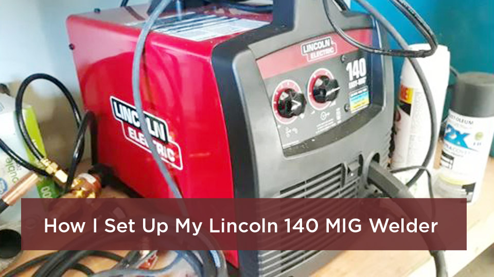
A MIG welding wire speed and voltage chart gives you a starting point, not a guaranteed final setting. The right combination depends on the wire diameter, base-metal thickness, shielding gas, joint design, welding position, power source, and travel speed.
Too much combined heat can cause burn-through or distortion. Too little can leave a tall, narrow bead with poor tie-in or incomplete fusion. The safest approach is to start with the chart inside your machine, run a test bead on matching scrap, and change one control at a time.
This guide explains how voltage and wire feed speed work together, provides practical starting charts, and shows you how to tune the arc without guessing. For a broader process comparison, see this guide to how MIG welding differs from TIG welding.
Quick Answer
Set MIG wire speed from the metal thickness, wire diameter, gas, and machine chart. Then adjust voltage until the arc is crisp and stable. If the wire repeatedly stubs into the work, add a little voltage or reduce wire speed. If the arc is long and erratic, reduce voltage or raise wire speed.
Key Takeaways
- Wire feed speed strongly affects welding current on a constant-voltage MIG machine. Voltage mainly changes arc length and bead profile.
- Use every chart as a starting point because machines, joints, gases, positions, and operator technique change the final setting.
- C25 gas works well for short-circuit mild-steel welding. Conventional spray transfer normally needs an argon-rich gas.
- Do not use the mild-steel chart for stainless steel, aluminum, or self-shielded flux-cored wire.
- Test on matching scrap and adjust one variable at a time before welding the finished part.
At a Glance
| Time Required | About 10 to 20 minutes to identify a baseline and tune it on scrap |
| Difficulty | Beginner to intermediate |
| Tools Needed | MIG welder, correct wire and gas, PPE, thickness gauge or caliper, clean matching scrap, pliers, and wire brush or grinder |
| Cost | Usually no extra cost beyond gas, wire, tips, and scrap already used for the job |
What Wire Speed and Voltage Control in MIG Welding
MIG is the common shop name for gas metal arc welding, or GMAW. On a typical constant-voltage power source, wire feed speed, measured in inches per minute or IPM, strongly affects welding current. More wire usually demands more current from the machine. Voltage mainly affects arc length, bead width, and bead height.
That does not mean wire speed alone equals heat. Weld heat input also depends on voltage, current, travel speed, transfer mode, and process efficiency. A slower travel speed normally puts more heat into each inch of the joint, while a faster travel speed puts in less.
A useful chart gets you close. A clean test coupon tells you whether the setting is actually right for your machine, joint, and technique.
If wire speed is too high for the selected voltage, the wire may push or stub into the work. If voltage is too high for the wire speed, the arc may become long, harsh, and unstable. The goal is a balanced arc with steady transfer and good fusion at both toes of the weld.
How to Read a MIG Welding Wire Speed and Voltage Chart
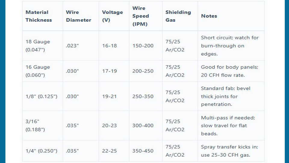
Most charts organize settings by base-metal thickness and wire diameter. A cell written as 19.0 V / 290 IPM means you should begin near 19 volts and 290 inches per minute, then test and tune.
Check These Details Before Using Any Chart
- Base metal: Mild steel, stainless steel, and aluminum need different wires, gases, and transfer modes.
- Thickness: Measure the thinner member at the joint, not the thickest part of the project.
- Wire classification and diameter: ER70S-6 solid steel wire does not use the same settings as self-shielded flux-cored wire.
- Shielding gas: C25, straight CO2, argon-rich spray gas, stainless blends, and pure argon all change arc behavior.
- Polarity: Solid wire is commonly DCEP. Many self-shielded flux-cored wires use DCEN, but the wire label and machine manual control.
- Joint and position: A fillet weld may need a different setting from a butt joint. Conventional spray is generally limited to flat and horizontal work.
- Machine capability: Input power, maximum output, duty cycle, inductance, and synergic programming can change the usable range.
Note: Two reputable charts can show different numbers because they were developed on different machines, joints, input voltages, and test conditions. Your machine’s door chart or owner manual should take priority.
Why the 1-Amp-Per-0.001-Inch Rule Is Only a Baseline
Miller’s parameter guide gives a rough mild-steel starting rule of about 1 amp for each 0.001 inch of thickness. It also suggests wire-speed multipliers when no chart is available: about 3.5 IPM per amp for .023-inch wire, 2 IPM per amp for .030-inch wire, 1.6 IPM per amp for .035-inch wire, and 1 IPM per amp for .045-inch wire.
For 1/8-inch steel, that rough rule begins near 125 amps. It produces about 250 IPM with .030-inch wire or 200 IPM with .035-inch wire. These are fallback estimates, not replacements for the machine chart.
MIG Welding Settings Chart for Mild Steel
The chart below reproduces published starting points for ER70S-6 solid wire with 75% argon and 25% CO2 at about 35 CFH. These values are useful for comparison, but they are not universal. Test the selected row on clean scrap that matches the joint thickness.
| Material Thickness | .023-Inch Wire | .030-Inch Wire | .035-Inch Wire | Practical Note |
|---|---|---|---|---|
| 22 ga. (0.030 in.) | 15.8 V / 125 IPM | 15.9 V / 95 IPM | 15.0 V / 88 IPM | Use short tacks or stitch welds to manage distortion. |
| 18 ga. (0.048 in.) | 17.0 V / 190 IPM | 16.3 V / 115 IPM | 15.8 V / 120 IPM | .023 or .030 wire is often easier to control on thin sheet. |
| 14 ga. (0.075 in.) | 18.0 V / 240 IPM | 17.3 V / 200 IPM | 16.5 V / 190 IPM | Check fit-up and keep the arc on the leading edge of the puddle. |
| 1/8 in. (0.125 in.) | 18.3 V / 350 IPM | 19.0 V / 290 IPM | 17.4 V / 230 IPM | A common short-circuit starting point for general fabrication. |
| 3/16 in. (0.188 in.) | 20.0 V / 480 IPM | 21.0 V / 400 IPM | 18.4 V / 265 IPM | Joint preparation or multiple passes may be needed. |
| 1/4 in. (0.250 in.) | Not listed | 24.3 V / 500 IPM | 21.0 V / 375 IPM | Confirm transfer mode and machine capacity. Do not assume C25 produces true spray. |
For .030-inch ER70S-6 on 1/8-inch mild steel with C25 gas, 19 V and 290 IPM is a useful published baseline. Miller’s separate rule-of-thumb method gives a lower 250-IPM estimate for the same thickness, which shows why charts must be tied to a specific setup.
Products Worth Considering
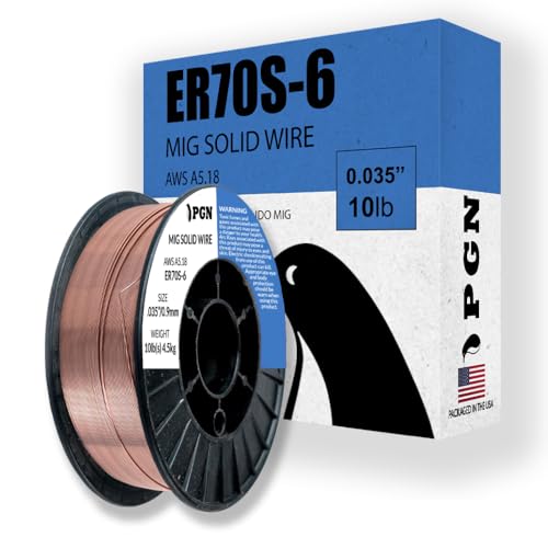
Do Your Best Work ... Color all your clients impressed with the precision and arc control of the ER70S-6 solid MIG welder wire. You'll love the low splatter whether you're performing single or multi-pass welds. Great for T-joints, butt welds & lap welds.

High-quality: ARCCAPTAIN's ER70S-6 mig welding wire .035" meets industry standards(Net Weight: 10lbs), ensuring consistent performance, superior strength. With its smooth feeding and stable welding parameters, you can achieve optimal penetration, high deposition rates, and exceptional overall welding performance.

ER70S-6 MIG WIRE: It's the most common wire of the copper-coated mild steel GMAW (MIG) wires for single or multiple pass welding.
What Changes When You Use Straight CO2?
Straight CO2 usually gives deeper penetration and costs less than C25, but it can produce more spatter and a harsher arc. Do not keep the same voltage and IPM without checking the machine chart. A gas change can require a new starting row and another test coupon.
Can C25 Produce Spray Transfer?
Do not plan on true conventional spray transfer with 75/25 argon/CO2. Miller’s pulsed MIG guidance says carbon-steel spray and pulsed transfer typically require at least 80% argon, with 90% argon and 10% CO2 being a common choice.
Pro Tip: Label saved settings with the exact wire, gas, joint, thickness, position, and machine input. A number such as “19/290” is not useful later if you cannot remember the rest of the setup.
MIG Settings for Stainless Steel and Aluminum
Do not copy the mild-steel chart to stainless steel or aluminum. Both materials need different consumables and shielding-gas choices, and aluminum normally uses spray or pulsed-spray transfer rather than short-circuit transfer.
Products Worth Considering
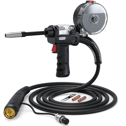
Smooth Wire Feeding: Experience seamless wire feeding with our spool gun. Featuring a 10-foot (3m) cable. Perfect fit for ARCCAPTAIN MIG205MP, MIG205PRO, MIG165PRO ensuring consistent and uninterrupted aluminum welding.

Smooth Welding Performance: Designed to handle 0.030-inch and 0.035-inch wires, our spool gun ensures stable arcs, minimal splatter, and high-precision welds. It is compatible with flux-cored wires, solid wires, and aluminum wires, making it ideal for various materials in automotive, marine, and construction projects.

Smooth Welding Performance: Designed to handle 0.030-inch and 0.035-inch wires, our spool gun ensures stable arcs, minimal splatter, and high-precision welds. It is compatible with flux-cored wires, solid wires, and aluminum wires, making it ideal for various materials in automotive, marine, and construction projects.
Stainless Steel Starting Points
For short-circuit welding on stainless steel, a traditional shielding gas is 90% helium, 7.5% argon, and 2.5% CO2. Some newer machines are programmed for 98% argon and 2% CO2. Follow the power-source program and filler-metal data sheet rather than assuming the gases are interchangeable.
| Thickness | .030-Inch Wire | .035-Inch Wire | Notes |
|---|---|---|---|
| 18 ga. | 21.5 V / 220 IPM | 23.0 V / 265 IPM | Use clean stainless-only tools and control interpass heat. |
| 14 ga. | 22.0 V / 255 IPM | 23.5 V / 300 IPM | Watch toe wetting and distortion. |
| 1/8 in. | 22.5 V / 290 IPM | 24.0 V / 335 IPM | Confirm the gas program and joint position on your machine. |
ER308L is commonly used for 304 stainless, but filler selection depends on the base-metal grades, service temperature, corrosion requirements, and joint design. Critical stainless work should follow an approved welding procedure.
Aluminum MIG Starting Guidance
Aluminum usually needs 100% argon, a spool gun or push-pull system, clean wire, and a push travel technique. Miller advises against short-circuit transfer for aluminum because fusion can be poor. Conventional spray works well but can burn through thin aluminum, while pulsed MIG gives better heat control when the machine supports it.
| Aluminum Wire Diameter | Typical Current Range | Typical Wire Speed | Use |
|---|---|---|---|
| .030 in. | About 100 to 150 A | About 500 to 600 IPM | Thin material where the machine and spool gun support the wire. |
| .035 in. | About 85 to 190 A | About 480 to 740 IPM | Common DIY and repair range with a compatible spool gun. |
| 3/64 in. | About 125 to 240 A | About 260 to 470 IPM | Stiffer wire with better feeding on higher-output systems. |
For filler choice, 4043 is easy to run and is common on many 6XXX alloys. ER5356 offers higher as-welded strength in some applications and is commonly paired with many 5XXX alloys. The correct choice depends on the exact base alloy, service temperature, corrosion exposure, and whether the finished part will be anodized.
Warning: Never weld an unknown aluminum casting, coated metal, closed container, wheel, pressure part, or structural component without identifying the material and following an approved repair procedure. Cleaning, heat treatment, prior service damage, and alloy selection can affect safety.
Factors That Change MIG Voltage and Wire Speed
No chart works in isolation. These variables can move the correct setting:
- Joint design and root gap: A fillet, lap, square butt, and beveled groove do not absorb heat or filler in the same way.
- Welding position: Vertical and overhead work often needs a smaller, faster-freezing puddle. Use a supported transfer mode and follow the procedure.
- Travel speed: Too fast can cause a narrow bead, poor tie-in, and lack of fusion. Too slow can create a wide bead, distortion, or burn-through.
- Contact-tip-to-work distance: Excessive distance changes current, arc behavior, and gas coverage. A common short-circuit range is roughly 1/4 to 5/8 inch, but the machine and process instructions control.
- Gun angle: A small push angle gives good visibility and often a flatter bead. A drag angle can produce a narrower bead and more penetration in some steel applications.
- Gas flow and drafts: Short-circuit MIG often runs near 25 to 35 CFH. Too little gas allows contamination, while too much can create turbulence.
- Surface condition: Rust, oil, paint, mill scale, moisture, and coatings can destabilize the arc and create porosity or fusion problems.
- Inductance or arc-control setting: On machines that provide it, this control changes how quickly current rises during short-circuit transfer. Begin at the factory setting and adjust only with the manual.
Step-by-Step Guide to Setting MIG Wire Speed and Voltage
- Identify the base metal and thickness. Measure the thinner joint member and confirm that the material is weldable with your process.
- Select the correct wire. Match the classification and diameter to the base metal, thickness, machine, and gun.
- Confirm polarity. Solid wire commonly runs DCEP. Check the wire label for flux-cored polarity because self-shielded and gas-shielded products can differ.
- Select the shielding gas and flow. Use the machine and wire recommendations. Check hoses, regulator, nozzle, and diffuser for leaks or blockage.
- Clean and fit the joint. Remove grease, moisture, paint, rust, and coatings from the weld zone. Clamp the work and attach the work lead to clean metal near the weld.
- Set the machine from its chart. Use the nearest match for wire diameter, gas, metal, thickness, and input power. Use a published general chart only when the machine chart is unavailable.
- Set CTWD and gun angles. Hold a consistent distance and use the correct work angle for the joint. Start with a travel angle of about 5 to 15 degrees unless the procedure specifies otherwise.
- Run a test bead on matching scrap. Use the same joint type, position, fit-up, and cleaning as the finished part.
- Inspect and adjust one variable. Correct obvious wire-speed-to-voltage imbalance first, then tune travel speed, CTWD, and technique.
- Verify fusion before production. For noncritical practice work, inspect bead shape and break or section a test joint when practical. For structural, pressure, lifting, vehicle-safety, or code work, follow a qualified WPS and required inspection.
How to Fine-Tune the Arc Without Chasing Your Tail
Make small changes and record them. On a digital machine, adjust about 0.5 to 1 volt or 10 to 25 IPM at a time. Larger changes can hide the real cause of the problem.
| Symptom | Likely Causes | First Correction |
|---|---|---|
| Wire repeatedly stubs or pushes the gun back | Voltage too low for wire speed, wire speed too high, or CTWD too short | Add a small amount of voltage or reduce IPM, then retest. |
| Long, harsh, erratic arc | Voltage too high for wire speed, wire feed interruption, or excessive CTWD | Reduce voltage slightly and inspect the feed path. |
| Wire burns back into the contact tip | Wire stops or slows, voltage is high relative to feed, incorrect run-in or burnback setting, or a restricted liner/tip | Inspect drive rolls, liner, tip, spool drag, and machine burnback controls before increasing wire speed. |
| Tall, narrow, convex bead with poor toe tie-in | Insufficient current, voltage too low, travel too fast, poor angle, or dirty metal | Clean the joint, shorten CTWD, and raise heat in small steps. |
| Wide, turbulent bead or undercut | Voltage too high, travel too fast, incorrect gun angle, or excessive heat | Reduce voltage slightly and correct travel angle and speed. |
| Excessive spatter | Voltage/WFS mismatch, long CTWD, wrong polarity, dirty metal, poor ground, or gas problem | Return to the chart baseline and verify polarity, CTWD, cleanliness, and work-lead contact. |
| Porosity or pinholes | Low or turbulent gas flow, drafts, leaks, blocked nozzle, moisture, oil, paint, or excessive CTWD | Stop welding, clean the joint, check gas flow at the gun, block drafts, and clean the nozzle. |
| Burn-through or severe distortion | Too much voltage/current, slow travel, large gap, or long continuous weld on thin metal | Reduce heat, increase travel speed, improve fit-up, and use spaced tacks or short segments. |
MIG Transfer Modes and Their Setting Requirements
| Transfer Mode | Typical Behavior | Best Fit | Limits |
|---|---|---|---|
| Short-circuit | Wire touches the puddle many times per second at relatively low voltage and current. | Thin steel, root work where permitted, and all-position welding. | Lower deposition, more spatter, and possible lack of fusion on thicker sections. |
| Globular | Large droplets cross the arc between short-circuit and spray ranges. | Usually a transition region rather than a target for clean manual GMAW. | More spatter and poorer bead appearance; generally flat or horizontal. |
| Conventional spray | Fine droplets cross a continuously established arc at higher current and voltage. | High-deposition welding on suitable thicker material. | Needs argon-rich gas and is generally limited to flat and horizontal positions. |
| Pulsed spray | The machine alternates peak and background current to transfer controlled droplets. | Lower average heat than conventional spray, less spatter, and better out-of-position control. | Requires a pulse-capable power source and the correct synergic program, gas, and wire. |
A pulsed-capable machine controls more than a simple average voltage and IPM pair. Start with the correct program for material, wire, diameter, and gas. Then use the manufacturer’s arc-length or trim control instead of copying conventional CV settings.
Shop Tips for More Repeatable MIG Settings
- Keep consumables clean: Replace worn contact tips and clean spatter from the nozzle and diffuser.
- Check drive-roll tension: Use enough pressure to feed smoothly without crushing or shaving the wire.
- Use the correct drive roll: Smooth V-groove rolls suit many solid steel wires, knurled rolls suit many flux-cored wires, and U-groove rolls are commonly used for soft aluminum wire.
- Keep the work lead close: Clamp to clean bare metal as near the weld as practical.
- Control drafts: Gas-shielded MIG is vulnerable outdoors. Use a wind screen without trapping fumes.
- Log successful settings: Record voltage, IPM, wire, gas, flow, CTWD, position, and joint type.
- Respect duty cycle: Do not use a high chart setting beyond the gun or power source rating.
Advanced Multi-Pass Setting Guidance
For multi-pass joints, use a qualified procedure when strength or code compliance matters. Do not automatically run a “cool root” followed by a hotter spray fill. The allowed transfer mode, root technique, groove design, preheat, interpass temperature, and pass sequence depend on the joint and governing procedure.
On ordinary noncritical practice joints, clean each pass, keep the arc at the leading edge of the puddle, and watch interpass temperature. A hotter workpiece may require faster travel or a short cooling pause, but do not make an unsupported wire-speed reduction that pushes the arc into an unstable transfer region.
Safety Rules Before You Change the Settings
Higher settings increase arc energy, spatter, fume generation, and the chance of igniting nearby material. Follow the welder manual, SDS information, shop hot-work rules, and the current safety guidance in AWS/ANSI Z49.1:2021. U.S. workplaces should also follow OSHA 29 CFR 1910 Subpart Q.
Warning: Wear a suitable welding helmet, safety glasses, dry gloves, flame-resistant clothing, and hearing protection as needed. Secure gas cylinders upright, remove or shield combustibles, provide ventilation, keep an extinguisher ready, and never weld a container that held a flammable or toxic substance.
OSHA’s general welding requirements call for removing or protecting fire hazards and require a fire watch in specified higher-risk conditions. They also identify a 35-foot area when evaluating nearby combustible material. Local rules, permits, and site conditions may require more protection.
Do not rely on a respirator as a substitute for source control and ventilation. Stainless steel, galvanized steel, painted steel, plated parts, and unknown coatings can create hazardous fumes. Stop and identify the coating before welding.
Wrapping It Up: Set a Baseline, Then Prove It
Start with the correct chart for your machine, wire, gas, metal, and thickness. Balance voltage and wire speed until the arc is stable, then use travel speed, CTWD, and gun angle to shape the bead. Do not judge success by appearance alone when the weld carries a safety-critical load.
Before a major job, weld a witness coupon that matches the real joint. Record the successful settings and, when practical, cut, bend, or break the coupon to check fusion. That habit saves more time than chasing a remembered number from a different machine.
Frequently Asked Questions
What wire speed should I use for 1/8-inch mild steel?
With .030-inch ER70S-6 wire and C25 gas, 19 V and about 290 IPM is one published starting point. Miller’s rule-of-thumb method gives about 250 IPM. Use your machine chart first, then test on matching scrap.
How do I match voltage to wire feed speed?
Begin with a matched pair from the machine chart. If the wire stubs into the work, add a little voltage or reduce wire speed. If the arc becomes long and unstable, reduce voltage or increase wire speed. Change only one control at a time.
What are the signs that MIG voltage is too high?
The arc may sound harsh or hissy, the puddle can become turbulent, and the bead may be overly wide or undercut. Excessive voltage can also contribute to unstable penetration. Reduce voltage in a small step and retest.
Does high wire speed cause burnback?
High wire speed more often causes stubbing, poor starts, spatter, or an overly hot weld. Burnback usually happens when wire feeding stops or slows, when voltage is too high relative to feed, or when run-in and burnback controls are incorrect.
Can I use solid-wire settings for self-shielded flux core?
No. Flux-cored wires have their own voltage, IPM, polarity, stickout, and positional requirements. Use the wire manufacturer’s data sheet and the machine’s flux-cored chart.
Why does aluminum need much higher wire speed?
Aluminum filler has different electrical and melting characteristics, and the process normally runs in spray or pulsed-spray transfer. Typical aluminum wire speeds can be several hundred IPM, so the spool gun or push-pull system must be compatible with the selected wire.
Sources
- Miller: MIG Welding, Setting the Correct Parameters — current, voltage, wire-size, and weld-bead troubleshooting fundamentals.
- MillerWelds Canada: MIG Welding Parameter Choices — published mild-steel and stainless volts/IPM starting tables used for the examples.
- Miller: Shielding Gas for MIG Welding — C25, CO2, argon-rich, stainless, aluminum, flow-rate, and CTWD guidance.
- Miller: MIG Welding Aluminum Best Practices — aluminum transfer-mode and heat-control guidance.
- American Welding Society: Free Safety Resources — AWS/ANSI Z49.1:2021 and welding safety fact sheets.
- OSHA: 29 CFR 1910 Subpart Q — U.S. workplace requirements for welding, cutting, and brazing.