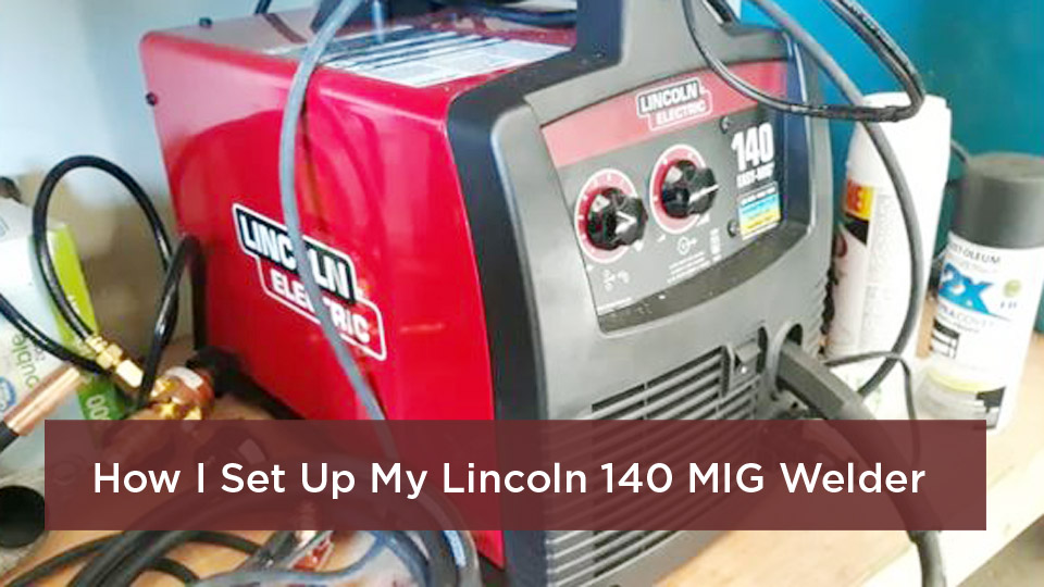
Pick the wrong welding process, and a simple repair can turn into extra grinding, poor fusion, excess distortion, or a weld that does not meet the job’s requirements. MIG vs TIG welding comes down to productivity, heat and filler control, material and thickness, joint access, finish quality, equipment, and operator skill. This guide explains the practical differences so you can choose with less guesswork.
Quick Answer
MIG welding is usually the better choice for fast fabrication, longer welds, and beginner-friendly work on steel or thicker aluminum. TIG welding is usually better for thin metal, precise heat control, clean visible beads, and specialty alloys. Neither process is automatically stronger; joint design, filler, settings, technique, and inspection determine weld quality.
Both methods can make sound welds when the equipment, filler metal, shielding gas, joint preparation, and technique match the job. The biggest practical difference is that MIG feeds a consumable wire automatically, while TIG uses a non-consumable tungsten electrode and lets the welder add filler separately.
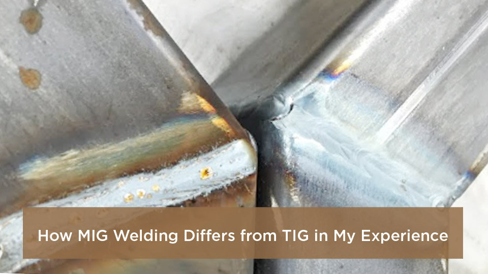
Photo by minoo-cn
Key Takeaways
- MIG, formally gas metal arc welding (GMAW), uses a continuously fed consumable wire and favors speed and deposition rate.
- TIG, formally gas tungsten arc welding (GTAW), uses a non-consumable tungsten electrode and separates heat control from filler addition.
- Material thickness alone does not choose the process; machine output, transfer mode, joint design, position, and procedure also matter.
- TIG usually produces little or no spatter, while MIG is generally faster and easier to mechanize or repeat.
- Both gas-shielded processes are sensitive to drafts and require clean material, correct gas coverage, ventilation, and proper PPE.
- Critical structural, pressure, vehicle-safety, lifting, or load-bearing work should follow the applicable code, engineered procedure, or manufacturer repair instructions.
At a Glance
| Time Required | MIG usually completes the same length of weld faster; TIG takes longer because heat and filler are controlled separately. |
| Difficulty | MIG: beginner-friendly to start, but high-quality fusion still takes practice. TIG: steeper learning curve and more hand-eye coordination. |
| Tools Needed | Correct power source, gun or torch, work lead, compatible wire or filler, shielding gas and regulator, metal-prep tools, and welding PPE. |
| Cost | Varies by amperage, input power, duty cycle, gas, and accessories. A basic MIG setup is often less expensive than a full AC/DC TIG setup. |
What’s in This Article
- What Is MIG Welding?
- What Is TIG Welding?
- Key Differences Between MIG and TIG Welding
- MIG vs TIG: Pros and Cons
- How to Choose Between MIG and TIG
- When to Choose MIG Welding
- When to Choose TIG Welding
- Materials, Thickness, and Joint Design
- Equipment and Setup Tips for MIG and TIG
- Transfer Modes, Current, and Polarity
- Common Mistakes and Troubleshooting
- Safety Considerations for MIG and TIG Welding
- Frequently Asked Questions
- Final Thoughts on MIG vs TIG Welding
- Sources
What Is MIG Welding?
MIG is the common shop name for gas metal arc welding (GMAW). The process feeds a continuous consumable wire electrode through a welding gun. The wire carries current, creates the arc, melts, and becomes filler metal in the joint. The gun also directs shielding gas around the arc and molten weld pool.
The American Welding Society treats “MIG” as a nonstandard but widely recognized name for GMAW. The wording matters because many steel applications use carbon dioxide or an argon-carbon dioxide blend, and carbon dioxide is an active gas rather than an inert one. “GMAW” is the most accurate process name when discussing all gas choices. See the AWS terminology explanation.
For carbon steel, common shielding choices include carbon dioxide and argon-rich blends, depending on the wire, transfer mode, position, and desired bead profile. Aluminum GMAW commonly uses argon, although the exact gas and filler wire must match the application. Always follow the wire manufacturer’s data and the machine setup chart rather than assuming one gas works for every job.
In practice, you set or select voltage and wire feed speed, establish the work connection, pull the trigger, and guide the gun along the joint. Automatic wire feeding reduces the coordination needed to start, but good fusion still depends on travel speed, contact-tip-to-work distance, work angle, travel angle, and correct settings. Two-handed gun support is often steadier when the joint allows it.
GMAW is common in general fabrication, manufacturing, automotive repair, brackets, trailers, gates, and frames because it offers high deposition rates and repeatable travel. It can weld thin or thick material within the machine’s rated range, but the correct transfer mode, joint preparation, and procedure are essential. For a current overview, see Miller’s GMAW basics.
Pro Tip: Clean the joint to sound metal and make a test weld on matching scrap. A short test can reveal poor gas coverage, wrong polarity, weak fusion, or excessive heat before you touch the finished part.
What Is TIG Welding?
TIG is the common name for gas tungsten arc welding (GTAW). It uses a non-consumable tungsten electrode in the torch to create the arc. The tungsten should not become part of the weld. If it touches the molten pool or filler, stop and recondition or replace it as needed.
Filler metal is added separately by hand or by a mechanized wire feeder. Some closely fitted joints can be autogenously fused without filler, but that choice must suit the material, joint design, service conditions, and applicable procedure.
GTAW normally uses an inert shielding gas, most often argon. Helium or argon-helium blends may be used for some applications. The welder controls amperage at the machine and may use a foot pedal, fingertip control, torch switch, or programmed slope controls. A remote control is useful but not mandatory on every setup.
Separating the arc from filler addition gives the welder precise control over the puddle and heat input. That makes GTAW useful for thin sheet, stainless tubing, aluminum, root passes, visible welds, and many specialty alloys. It can also weld thick material, although its lower deposition rate often makes it slower than GMAW for filling large joints.
TIG asks more from the operator. Arc length, torch angle, travel speed, filler timing, shielding coverage, and heat must stay coordinated. The process can produce clean beads with little or no spatter, but it is not defect-proof. Poor cleaning, weak gas coverage, tungsten contamination, incorrect filler, or excess heat can still cause porosity, oxidation, cracking, or lack of fusion. See Miller’s GTAW basics.
Key Differences Between MIG and TIG Welding
MIG and TIG both use an electric arc and external shielding gas, but they behave differently in the shop. Compare the wire or electrode system, filler control, deposition rate, heat control, equipment, joint access, and required finish before choosing.
| Factor | MIG / GMAW | TIG / GTAW |
|---|---|---|
| Arc electrode | Consumable wire | Non-consumable tungsten |
| Filler addition | Wire feeds automatically and is normally deposited continuously | Separate rod or wire is added only as needed; some joints use no filler |
| Productivity | Usually faster with a higher deposition rate | Usually slower, especially when manually feeding filler |
| Heat and puddle control | Controlled through voltage, wire feed, travel, mode, and machine features | Fine manual or programmed amperage control; filler is independent of the arc |
| Appearance and cleanup | Can be clean, but short-circuit or globular transfer may create more spatter | Little or no spatter when technique and shielding are correct |
| Learning curve | Easier to start because wire feeding is automatic | Harder to coordinate torch, filler, arc length, and amperage |
| Draft sensitivity | Shielding gas can be disturbed outdoors or near fans | Also sensitive to drafts; reactive metals may need trailing shields or back purging |
| Typical entry cost | Basic steel-capable systems are often less expensive | AC/DC, high-frequency, remote controls, and water cooling can raise cost |
Electrode and Filler Material
GMAW combines the electrode and filler into one continuously fed wire. GTAW creates the arc with tungsten and keeps filler separate. This is why MIG can deposit metal quickly, while TIG lets you pause filler addition without stopping the arc.
Neither process lets you choose filler by appearance alone. The wire or rod must be compatible with the base metal, required mechanical properties, service temperature, corrosion conditions, and governing procedure. For coded or safety-critical work, use the specified classification and lot controls.
Shielding Gas and Weld Protection
GMAW gas selection changes with material and transfer mode. Carbon steel may use carbon dioxide or argon-carbon dioxide blends. Stainless applications can use specialized argon-based blends. Aluminum commonly uses argon or an argon-helium blend. GTAW commonly uses argon, with helium blends used where more arc energy or penetration is needed.
Gas flow is not a “more is better” setting. Too little flow, leaks, a blocked nozzle, long arc length, or drafts can let air reach the pool. Excessive flow can create turbulence that draws surrounding air into the shielding envelope. Start with the equipment and consumable manufacturer’s recommendation, then diagnose the entire gas path if porosity appears.
Speed and Productivity
MIG generally completes long welds faster because the wire feeds continuously and deposition rates can be high. TIG moves more slowly because the welder manages the torch and filler separately. That slower pace can be worthwhile for a precise root, a small repair, a visible bead, or a part where rework would be costly.
Heat Control and Material Thickness
TIG is often favored on thin material because the operator can taper amperage and control filler independently. MIG can also weld thin sheet with suitable wire, short-circuit or pulsed capability, careful fit-up, and good technique. On thick work, MIG’s deposition rate is an advantage, but TIG can still make sound multi-pass welds or high-quality root passes.
Do not choose solely from a thickness chart found online. The machine’s output range, duty cycle, wire or tungsten size, joint geometry, travel speed, base-metal condition, preheat, and welding position all affect the usable range.
Weld Quality, Strength, and Appearance
TIG often makes a narrow, smooth bead with little spatter. MIG can also produce attractive welds when transfer mode, settings, fit-up, and technique are correct. Appearance is not proof of strength: a smooth bead can still hide incomplete fusion, internal porosity, cracking, or inadequate penetration.
A sound weld comes from the right joint design, filler, procedure, technique, and inspection—not from choosing MIG or TIG by name alone.
Skill Level Required
MIG is usually easier for a beginner to start because the gun supplies filler automatically. The operator can focus on gun position, travel, stickout, and puddle response. TIG requires more coordination because the operator controls the torch, arc length, filler timing, and often amperage at the same time.
Easy to start does not mean easy to qualify. A MIG bead can look acceptable while lacking fusion, especially with low heat input or poor travel technique. Practice on coupons, cut and etch sample welds when appropriate, and use qualified inspection for critical work.
Cost Considerations
Basic MIG machines are often less expensive than AC/DC TIG systems with high-frequency start, remote amperage control, and water cooling. Total cost also includes input power, cylinder ownership or rental, regulator, gun or torch consumables, filler inventory, PPE, ventilation, and metal-prep tools.
Labor changes the calculation. MIG’s higher deposition rate can lower time per joint. TIG may reduce spatter cleanup or rework on precise, high-value parts. Compare the entire job rather than only the machine price.
MIG vs TIG: Pros and Cons
This side-by-side view summarizes common advantages and limits. These are general tendencies, not guarantees for every machine, material, or welding procedure.
| Aspect | MIG Welding Pros | MIG Welding Cons | TIG Welding Pros | TIG Welding Cons |
|---|---|---|---|---|
| Speed | Fast for production, repairs, and long seams | High deposition can overheat thin or poorly fitted parts | Lets the operator meter heat and filler closely | Slow for filling large joints |
| Ease of Use | Automatic wire feed shortens the initial learning curve | Poor settings can still create cold lap, spatter, or burn-through | Excellent control once technique is developed | Requires strong hand-eye coordination |
| Weld Quality | Can produce code-quality welds with the correct procedure | Lack of fusion may be hard to spot from bead appearance alone | Precise puddle and filler control with little spatter | Tungsten or atmospheric contamination can quickly damage quality |
| Appearance | Can produce smooth beads with spray or pulsed transfer | Some modes create more spatter and cleanup | Produces controlled beads with little or no spatter | A neat bead still does not prove internal soundness |
| Cost | Basic systems are widely available | Tips, liners, nozzles, drive parts, wire, and gas add operating cost | Can reduce cleanup on precise work | Full-featured AC/DC equipment and accessories can cost more |
| Versatility | Productive on carbon steel, stainless, and aluminum with the right setup | Gas-shielded operation is vulnerable to wind | Useful on thin metal, root passes, and many specialty alloys | Reactive metals may need extensive auxiliary shielding |
MIG gives you productivity and a shorter initial learning curve. TIG gives you separate control of heat and filler. The better process is the one that meets the material, joint, quality, access, and production requirements.
How to Choose Between MIG and TIG
Use the questions below before buying equipment or committing to a procedure.
- Identify the exact alloy. “Steel” or “aluminum” is not specific enough for filler selection or heat treatment concerns.
- Measure the actual thickness and joint gap. Thin edges, uneven fit-up, and open roots change heat needs.
- Define the service. A decorative bracket, exhaust tube, pressure boundary, roll cage, and lifting point do not have the same acceptance requirements.
- Check access and position. A foot pedal may not be practical under a vehicle, and some GMAW transfer modes are limited by position.
- Set the production priority. Choose MIG when deposition and speed dominate; consider TIG when precision, root control, or appearance dominates.
- Check power and duty cycle. Confirm that the circuit, machine output, and cooling system support the planned weld length and amperage.
- Confirm shielding conditions. Both processes need protection from wind; outdoor work may call for wind screens or a different process.
- Follow the governing procedure. Codes, drawings, filler specifications, and OEM repair manuals override a general comparison guide.
Note: Flux-cored arc welding is not simply “MIG without gas.” It is a separate process with tubular wire. Self-shielded flux-cored wire may be more practical outdoors, while gas-shielded flux-cored wire still needs protection from drafts.
Products Worth Considering
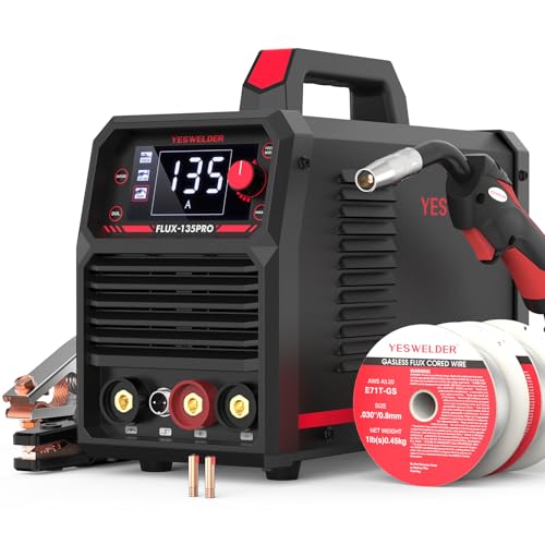
READY OUT OF THE BOX: Start welding immediately! It masterfully handles Gasless Flux Core MIG, Stick, and Lift TIG (Extra Lift TIG torch required). This budget-friendly 3-in-1 machine includes extra E71T-GS .030''&.035'' flux core wires, known for its smooth arc and high feedability. Say goodbye to heavy shielding gas cylinders—perfect for outdoor, windy, or all-position welding.

3-in-1 Multi Process Welder: Designed to handle Gasless MIG welder, MMA, and Lift TIG perfectly, this 110V welding machine is a garage essential for home DIY and fast farm repairs.(Lift TIG Torch NOT included)

MULTIFUNCTIONAL: A 4-in-1 welder, capable of Flux Core MIG/Gas MIG/ Stick/Lift TIG (need to purchase extra tig lift torch). This unit caters to a wide range of welding applications and meets your various welding needs.
When to Choose MIG Welding
Choose MIG when you need high productivity, long welds, repeated joints, or a shorter setup-to-production learning curve. It is common for mild-steel brackets, frames, trailers, gates, sheet-metal repairs, and manufacturing. The machine, transfer mode, filler, gas, and procedure must still suit the part.
MIG also makes sense when the finished weld will be coated or when production speed matters more than a show-quality bead. Do not assume grinding can correct a weak weld; grinding changes appearance, not internal fusion.
Use this basic MIG butt-joint practice flow for clean mild-steel coupons:
- Verify the material, thickness, wire classification, shielding gas, polarity, and machine capacity.
- Remove paint, rust, oil, heavy mill scale, and moisture from the joint area using a safe method.
- Prepare the edge and root opening as required by the joint design or welding procedure.
- Set voltage and wire feed speed from the machine or consumable chart, then test on matching scrap.
- Tack the joint in a sequence that holds alignment and limits movement.
- Support the gun steadily, maintain the recommended contact-tip-to-work distance, and watch the leading edge of the puddle.
- Inspect the test and finished weld for profile, undercut, porosity, overlap, burn-through, and signs of incomplete fusion.
- Allow the weldment to cool as required by the material and procedure; do not quench it unless the procedure specifically permits quenching.
When to Choose TIG Welding
Choose TIG when you need close control on thin metal, a precise root, clean stainless work, aluminum repair, specialty alloys, or a visible bead. It is common on tubing, custom exhaust parts, food or process equipment, motorsports fabrication, aluminum components, and high-value repairs.
TIG can help manage distortion because the operator can adjust amperage during the weld, but it does not automatically mean lower total heat input. Slow travel, repeated reheating, or an oversized bead can put substantial heat into the part. Use tack spacing, sequence, chill fixtures where permitted, pulse settings when useful, and the specified interpass temperature.
Use this basic TIG lap-joint practice flow for thin stainless coupons:
- Verify the stainless grade, thickness, filler classification, current type, polarity, tungsten, and shielding plan.
- Remove oil with a non-chlorinated cleaner approved for the task, then clean the joint with abrasives or a stainless brush reserved for stainless.
- Fit and tack the coupons with a consistent overlap and minimal gap.
- Set amperage, gas flow, pre-flow, and post-flow from reliable equipment or procedure guidance.
- Start the arc without scratching the tungsten on the work when the machine provides lift-arc or high-frequency start.
- Hold a short, stable arc and add small, even amounts of filler while maintaining shielding over the hot pool.
- End the weld by filling the crater and tapering current when the equipment allows.
- Keep post-flow over the tungsten and hot weld, then inspect for oxidation, undercut, incomplete fusion, and contamination.
Materials, Thickness, and Joint Design
Carbon and Mild Steel
MIG is often the productivity choice for mild steel because wire and gas options are widely available and deposition is fast. TIG is useful for thin sheet, tubing, precise roots, and repairs where filler control matters. On hardenable steels, preheat, interpass temperature, hydrogen control, and post-weld treatment may be more important than the process name.
Stainless Steel
Both processes can weld stainless steel. TIG is common where bead control, purge quality, or appearance matters. MIG is useful for production and thicker sections with the correct wire and gas. Keep carbon-steel tools away from stainless surfaces, and control heat and shielding to reduce oxidation and corrosion problems. Stainless welding fumes can contain hazardous chromium and nickel compounds, so effective fume control is essential.
Aluminum
TIG is often preferred for thin aluminum and precise repair because AC TIG equipment provides oxide-cleaning action and close heat control. MIG is productive on thicker aluminum when the machine supports the required output and transfer mode. Soft aluminum wire may require a spool gun or push-pull system to prevent feeding problems. Clean the oxide and contamination with tools dedicated to aluminum, and match filler to the alloy and service.
Titanium and Reactive Metals
TIG is commonly used for titanium and other reactive metals, but the normal torch cup may not provide enough shielding by itself. The hot weld, heat-affected zone, root, and filler can require trailing shields, backing gas, or an inert chamber. Color and surface appearance can indicate exposure, but acceptance must follow the applicable procedure.
Joint Design Matters
Butt, lap, fillet, corner, and open-root joints place different demands on the arc. A thick square butt may not achieve fusion through the full section, regardless of process. Bevel angle, root face, root opening, backing, weld size, position, and pass sequence should come from a drawing, tested procedure, or qualified design—not guesswork.
Equipment and Setup Tips for MIG and TIG
Your setup affects the weld as much as hand skill. Match the power source, consumable, gas, polarity, current type, torch or gun, work connection, and cooling capacity to the metal before striking an arc.
Products Worth Considering

Complete TIG Torch Kit - 71pcs Tig Welding Torch accessories (consumables) kit. This set includes all the essential TIG torch accessories and consumables, so you can get started on your welding projects right away.

Complete 123-Piece Set:All necessary TIG torch accessories and consumables for WP-17, WP-18, and WP-26 torches.
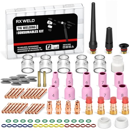
87 PCS tig torch accessories (consumables) with 12 tig cups.
MIG Setup Checklist
- Install drive rolls that match the wire type and diameter.
- Use the correct contact tip, liner, and gun length for reliable feeding.
- Confirm solid-wire GMAW polarity from the wire and machine instructions; many common solid wires use electrode-positive polarity.
- Check the cylinder, regulator, hose, gas connection, gun diffuser, O-rings, and nozzle for leaks or blockage.
- Keep the work clamp connection clean and secure.
- For aluminum, use the specified liner and drive system; a spool gun or push-pull gun can improve feeding.
- Set voltage and wire feed together rather than changing one control at random.
TIG Setup Checklist
- Choose a tungsten type and diameter that the machine manufacturer permits for the planned AC or DC current.
- Prepare the tungsten using a dedicated grinder or contamination-free method.
- Use DC electrode negative for many steel and stainless applications and AC for typical aluminum welding, unless a qualified procedure specifies otherwise.
- Choose a cup, collet, gas lens, torch size, and gas flow that provide coverage without excessive turbulence.
- Confirm filler classification and keep rods clean and dry.
- Set pre-flow, starting current, main amperage, downslope, crater control, and post-flow as available.
- Use an air-cooled or water-cooled torch within its rating and duty cycle.
Input Power and Duty Cycle
Do not compare machines by maximum amperage alone. Check the rated output at a stated duty cycle, input voltage and amperage, generator compatibility, extension-cord requirements, and whether the machine supports the needed process features. Repeatedly exceeding duty cycle can trigger thermal protection and shorten productivity.
Transfer Modes, Current, and Polarity
Common GMAW Transfer Modes
- Short-circuit transfer: The wire repeatedly contacts the pool. It is useful for sheet metal, gaps, and many positions, but poor parameters or technique can cause incomplete fusion.
- Globular transfer: Large droplets cross the arc and can create more spatter. It has a narrower range of desirable applications.
- Spray transfer: Fine droplets cross without repeated short circuits. It offers high deposition and smooth transfer but generally needs argon-rich gas, higher current, and suitable positions.
- Pulsed spray transfer: Current alternates between peak and background levels. It can lower average heat and expand the useful range, but it still requires compatible equipment, wire, gas, and settings.
Transfer mode affects penetration profile, spatter, heat input, position, and deposition rate. It is one reason a simple statement such as “MIG is for thick metal” is incomplete.
TIG Current and Start Methods
DC electrode negative is common for steel, stainless steel, nickel alloys, and many other metals. AC is common for aluminum and magnesium because it combines heating with oxide-cleaning action. Specialized applications can differ, so follow the qualified procedure.
High-frequency start establishes the arc without touching the work. Lift-arc start limits contamination by using a controlled touch-and-lift sequence. Scratch start is simpler but can contaminate the tungsten or work and gives less starting control.
Common Mistakes and Troubleshooting for MIG and TIG
Most defects trace back to a combination of preparation, setup, gas coverage, heat input, joint access, and travel technique. Diagnose the cause rather than covering the bead with another pass.
| Symptom | Possible Causes | Checks |
|---|---|---|
| Porosity | Dirty metal, moisture, drafts, leaks, blocked nozzle or cup, wrong flow | Clean and dry the joint; leak-check the gas path; shield drafts; verify flow at the torch |
| Burn-through | Excess heat, slow travel, large gap, poor sequence | Reduce heat input, improve fit-up, use shorter welds or a backing method if permitted |
| Incomplete fusion | Low heat, fast travel, wrong angle, oversized joint, poor access | Verify parameters and joint prep; direct the arc into both members; test on a coupon |
| Excess MIG spatter | Voltage-wire feed mismatch, wrong polarity, long stickout, unstable gas or transfer | Return to chart settings, verify polarity and consumables, and correct gun distance |
| Unstable TIG arc | Contaminated tungsten, poor work connection, wrong tungsten size or current, excessive arc length | Regrind or replace tungsten, shorten the arc, and check setup and ground path |
| Discolored TIG weld | Weak shielding, excess heat, insufficient post-flow or back purge | Improve coverage, travel and purge; compare color limits with the procedure |
| Wire feeding problems | Wrong drive roll, worn tip, dirty liner, excessive drive tension, bent cable | Match consumables, clean or replace worn parts, and keep the cable path smooth |
Watch for these common errors:
- Skipping material identification and joint cleaning
- Using the wrong shielding gas, filler, current type, or polarity
- Copying settings that do not match the machine, wire, thickness, or joint
- Running too much heat or moving too slowly on thin material
- Holding the MIG gun too far from the work
- Using a long TIG arc or touching the tungsten to the pool
- Ignoring gas leaks, drafts, and contaminated consumables
- Trusting bead appearance without checking fusion and acceptance criteria
- Skipping test welds on representative scrap
Note: If a weld repeatedly cracks, stop. Do not keep adding passes until you identify the alloy, filler, joint restraint, hydrogen risk, heat treatment, and procedure requirements.
Safety Considerations for MIG and TIG Welding
Welding exposes the operator and nearby people to intense optical radiation, hot metal, sparks, electrical hazards, fire, fumes, gases, and noise. OSHA lists metal fumes, ultraviolet radiation, burns, eye damage, electrical shock, and other hazards for welding operations. Review the OSHA welding hazards and controls before setting up a work area.
PPE and Arc Radiation
Wear a welding helmet with a filter shade suitable for the process and current, safety glasses with side protection under the helmet, dry welding gloves, flame-resistant clothing that covers exposed skin, and leather footwear. Add hearing, respiratory, or other protection based on a hazard assessment. Use welding screens to protect nearby people from arc radiation.
Fumes and Ventilation
Neither TIG nor MIG is fume-free. Fume composition depends on the base metal, filler, coating, process, and parameters. Stainless steel, galvanized steel, plated parts, and metals containing chromium, nickel, manganese, lead, cadmium, or beryllium can create serious exposure concerns. Use source capture or local exhaust where practical and keep your head out of the plume. NIOSH provides current welding fume guidance.
A respirator is not a substitute for feasible engineering controls. When respiratory protection is required at work, it must be selected for the hazard and used under a compliant program that includes medical evaluation, fit testing, training, and maintenance.
Shielding Gases and Confined Spaces
Argon, helium, and carbon dioxide can displace oxygen. This is especially dangerous in tanks, pits, vessels, and other enclosed or low areas. Do not enter or weld in a confined space without the required atmospheric testing, ventilation, permit, attendant, rescue provisions, and other controls.
Coatings and Cleaning Solvents
Identify paint, plating, galvanizing, primers, oils, and chemical residues before heating the part. Remove coatings using a controlled method or use the protection required for the specific hazard. Never weld near chlorinated solvents or on metal that is wet with an unknown cleaner; arc radiation and heat can break down chlorinated compounds and form highly toxic gases, including phosgene.
Warning: Never weld, cut, braze, or heat a tank, drum, pipe, wheel, shock absorber, fuel-system part, or sealed container until a qualified procedure confirms it has been emptied, cleaned, isolated, vented, and made safe. Residues or pressure can cause fire, explosion, or toxic exposure.
Fire, Electrical, and Cylinder Safety
Remove combustible material, inspect hidden spaces where sparks can travel, keep suitable fire protection available, and use a fire watch when required. Mark or guard hot metal after welding. Keep cables, connectors, electrode holders, guns, torches, and work leads in serviceable condition. Avoid wet clothing and wet work areas.
Secure compressed-gas cylinders upright with an approved chain or strap, protect valves, use the correct regulator, and keep cylinders away from sparks, heat, and damage. Close cylinder valves when the system is not in use and follow the gas supplier’s handling instructions.
Critical and Code-Governed Work
Practice-level instructions are not a welding procedure specification. Structural steel, pressure equipment, lifting devices, roll cages, suspension parts, vehicle frames, trailer couplers, fuel systems, and other safety-critical work may require engineering, a qualified WPS, a qualified welder, inspection, and nondestructive testing. The AWS D1.1:2025 Structural Welding Code—Steel, for example, addresses procedure qualification, welder qualification, fabrication, inspection, and acceptance for covered structural-steel work.
Frequently Asked Questions
Is MIG welding easier to learn than TIG?
MIG is usually easier to start because the machine feeds filler wire automatically. TIG requires the operator to control the torch, arc length, filler, and often amperage at the same time. However, producing consistently sound, code-acceptable MIG welds still requires training and practice.
Which is better for welding aluminum?
TIG is often better for thin aluminum, small repairs, and precise visible work. MIG is usually faster on thicker aluminum when the power source, wire, transfer mode, shielding gas, and feeding system are suitable. A spool gun or push-pull gun can help feed soft aluminum wire.
Can you use MIG wire as filler in TIG welding?
Some solid GMAW wires share an alloy classification with GTAW cut-length filler, but do not assume any spool wire is suitable. Confirm the filler classification, diameter, surface condition, traceability, and governing procedure. Do not use flux-cored wire as TIG filler.
Does MIG or TIG make the stronger weld?
Neither process is automatically stronger. Strength and service performance depend on the base metal, filler, joint design, weld size, fusion, defects, heat treatment, procedure, and inspection. Both GMAW and GTAW can produce code-quality welds when properly qualified and performed.
Which process costs less for a beginner?
A basic MIG setup for mild steel often costs less than a full AC/DC TIG setup. Compare more than the machine price: include electrical service, gas, cylinder, regulator, consumables, torch or gun accessories, PPE, ventilation, and the materials you plan to weld.
Can you MIG or TIG weld outdoors?
You can weld outdoors only when you can protect the shielding envelope from wind and meet all fire and ventilation requirements. Even a light draft can cause porosity. Wind screens may help, but self-shielded flux-cored or stick welding can be more practical for some outdoor jobs.
Do you need AC TIG to weld aluminum?
AC TIG is the normal choice for manual aluminum welding because it provides oxide-cleaning action and controllable penetration. Specialized DC techniques exist, but they are not the default beginner setup and should follow proven equipment and procedure guidance.
Final Thoughts on MIG vs TIG Welding
MIG gives you speed, continuous filler delivery, and strong productivity across many fabrication jobs. TIG gives you separate control of the arc and filler, little spatter, and precise puddle control for thin, visible, or demanding work.
Choose the process that matches the exact alloy, thickness, joint, position, finish, production rate, power supply, and acceptance standard. Make test welds on representative material, verify settings from reliable data, and inspect the result before trusting it in service.
For noncritical practice, learning both processes makes you more adaptable. For anything that protects people or carries pressure, structural load, suspension load, towing load, or lifting load, use the applicable engineered procedure and qualified personnel.
Sources
- OSHA: Welding, Cutting, and Brazing—Hazards and Solutions — welding radiation, fume, burn, electrical, and PPE hazards.
- OSHA 29 CFR 1910.252: General Requirements — fire prevention, ventilation, confined spaces, coatings, eye protection, and hot-work requirements.
- NIOSH: Welding Fumes and Manganese — welding-fume exposure information and control resources.
- AWS D1.1/D1.1M:2025 Structural Welding Code—Steel — qualification, fabrication, inspection, and acceptance requirements for covered structural-steel work.
- Miller: Understanding the Basics of MIG Welding for Mild Steel — GMAW equipment, wire feed, shielding gas, and setup fundamentals.
- Miller: Guide to TIG Welding Basics — GTAW operation, tungsten, filler, current, and equipment fundamentals.