A poor MIG setup can ruin a weld before you pull the trigger. Gas flow, wire type, polarity, wire speed, voltage, clean metal, and the condition of your consumables all affect the final bead.
Too little shielding gas can expose the puddle to air and cause porosity. Too much flow can waste gas and create turbulence that pulls surrounding air into the shielding stream.
This guide shows you how to set up a gas-shielded Metal Inert Gas (MIG), or Gas Metal Arc Welding (GMAW), machine in a clear and practical way. You will learn how to install the wire, connect and test the gas system, set polarity, choose starting parameters, troubleshoot common problems, and shut the system down safely.
Quick Answer
To set up a MIG welder with gas, match the solid wire, contact tip, drive rolls, liner, polarity, and shielding gas to the metal. Secure the cylinder, connect the regulator and hose, set gas flow while gas is moving, attach the work clamp to clean metal, use the machine chart, and test on matching scrap.
Key Takeaways
- Most gas-shielded solid-wire MIG setups use direct current electrode positive (DCEP), but you should confirm the wire label and machine manual.
- For indoor short-circuit welding on mild steel, 20 to 25 cubic feet per hour (CFH) is a common starting range, not a universal setting.
- Match the contact tip, drive-roll groove, liner, and wire diameter before feeding the wire.
- Use the voltage and wire-feed chart supplied with your specific machine, then fine-tune one variable at a time on clean scrap.
- Use ventilation, proper PPE, cylinder restraint, fire controls, and safe shutdown procedures every time you weld.
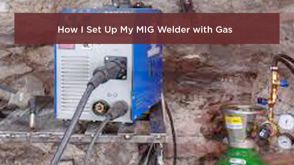
Photo by theweldspace
At a Glance
| Time Required | About 20 to 40 minutes for a basic setup; longer when changing wire, liner, drive rolls, or cylinders |
| Difficulty | Beginner to intermediate; hands-on training is recommended before structural or safety-critical work |
| Tools Needed | MIG welder, matching wire and consumables, shielding gas cylinder, regulator or flowmeter, hose, PPE, clamps, wire brush or grinder, and leak-detection solution |
| Cost | Varies by cylinder ownership or rental, local gas supply, wire type, and replacement consumables |
What’s in This Article
- What Is MIG Welding and Why Use Shielding Gas?
- Before You Begin Setting Up a MIG Welder With Gas
- Essential Equipment for MIG Welding Setup
- Safety Considerations Before Starting
- Step-by-Step Guide to Setting Up Your MIG Welder
- Choosing the Right Shielding Gas for Your Project
- Adjusting MIG Welder Settings for Optimal Performance
- Common Mistakes When Setting Up a MIG Welder With Gas
- MIG Welding Techniques for Clean, Strong Welds
- Shutdown and Storage
- Applications and Tips for DIY and Professional Welders
- Frequently Asked Questions
- Sources
- Safety Disclaimer
- Conclusion
What Is MIG Welding and Why Use Shielding Gas?
MIG welding, also called Gas Metal Arc Welding (GMAW), feeds a continuous wire electrode through a welding gun. The arc melts the wire and the edges of the base metal, and the molten puddle cools to form the joint.
Shielding gas flows through the nozzle and limits contact between the molten weld metal and the surrounding atmosphere. Poor coverage can contribute to porosity, oxidation, an unstable arc, rough bead shape, and reduced weld quality.
Gas-shielded wire welding works on mild steel, stainless steel, and aluminum when you use a compatible wire, gas, feeding system, and machine setup. In common North American usage, people often call the process MIG even when the shielding blend contains active gases such as carbon dioxide.
Before You Begin Setting Up a MIG Welder With Gas
Plan the complete setup before you connect the welder. A few checks at the start can prevent poor feeding, wasted gas, damaged consumables, and unsafe operation.
- Identify the base metal, thickness, joint type, and welding position.
- Choose a wire classification and diameter that your machine supports.
- Match the shielding gas to the wire, material, and transfer mode.
- Confirm the contact tip, drive rolls, liner, and wire guides match the wire.
- Check the machine manual for input power, polarity, duty cycle, and starting settings.
- Prepare clean scrap with the same material and thickness as the project.
Note: Do not treat a settings chart from another machine as a substitute for your own manual. Output calibration, wire diameter, gas blend, joint design, and input voltage can change the correct voltage and wire-feed speed.
Essential Equipment for MIG Welding Setup
You need a MIG welder with the output range and input-power requirements needed for your work. Many machines include a parameter chart inside the wire compartment.
The MIG gun carries the wire, welding current, and shielding gas. Inspect the cable, trigger, neck, diffuser, contact tip, and nozzle before use.
Use solid MIG wire when your procedure calls for external shielding gas. ER70S-6 is a common mild-steel wire. Typical home-shop diameters include 0.023, 0.030, and 0.035 inch, but the correct choice depends on the metal thickness and machine capacity.
Match the feeding parts to the wire. Solid steel wire commonly uses a V-groove drive roll. Soft aluminum wire normally needs a U-groove roll, a suitable liner, and often a spool gun or push-pull system to reduce feeding trouble. Never force an oversized wire through a smaller contact tip or liner.
You also need a shielding gas cylinder, the correct regulator or flowmeter for that gas, an undamaged gas hose, a work clamp, and suitable cleaning and clamping tools. The work clamp completes the welding circuit; it is not a substitute for the machine’s protective electrical grounding system.
For personal protection, use a welding helmet with the correct shade for the amperage and process, safety glasses with side protection, leather welding gloves, flame-resistant clothing, and leather footwear. Use local exhaust or another effective ventilation method when indoor conditions require it.
Products Worth Considering

3-in-1 Multi Process Welder: Designed to handle Gasless MIG welder, MMA, and Lift TIG perfectly, this 110V welding machine is a garage essential for home DIY and fast farm repairs.(Lift TIG Torch NOT included)

4-IN-1 MIG Welder: The welder machine offers GAS MIG/Flux Core MIG/Lift TIG/ MMA welding modes (Note: WP-17V TIG torch must be purchased separately). It can easily handle welding stainless steel, carbon steel, and even thicker steel materials, meeting diverse welding requirements.

MULTIFUNCTIONAL: A 4-in-1 welder, capable of Flux Core MIG/Gas MIG/ Stick/Lift TIG (need to purchase extra tig lift torch). This unit caters to a wide range of welding applications and meets your various welding needs.
Safety Considerations Before Starting
Welding creates heat, sparks, ultraviolet and infrared radiation, fumes, gases, noise, and electrical hazards. OSHA identifies burns, eye damage, electrical shock, and exposure to metal fumes among the main welding hazards.
Use ventilation that captures or removes fumes without blowing the shielding gas away from the weld. A strong cross-draft can disturb gas coverage and cause porosity. Confined-space welding requires specific training, ventilation, atmospheric testing, rescue planning, and compliance with applicable rules.
Argon and carbon dioxide are not flammable, but they can displace oxygen. Never rely on smell to detect an oxygen-deficient atmosphere.
Warning: Secure every compressed-gas cylinder upright with a chain, strap, or approved restraint before removing the cap or opening the valve. Keep the cylinder away from sparks, impact, excessive heat, and electrical circuits.
Remove paint, plating, oil, rust, and unknown coatings from the weld area using a safe method. Do not weld material cleaned with chlorinated solvents, and do not weld on a container, tank, pipe, or enclosed part unless it has been properly identified, cleaned, vented, and made safe by a qualified person.
Move paper, solvents, fuel, rags, wood dust, and other combustibles away from the hot-work area. Keep the correct fire extinguisher nearby, protect hidden spaces from sparks, and maintain a fire watch when the surroundings can ignite.
Step-by-Step Guide to Setting Up Your MIG Welder
Use this sequence as a general setup flow. Your welder, regulator, wire, and gas-cylinder instructions control whenever they differ from this guide.
1. Prepare the Welder and Work Area
- Place the welder on a stable, dry, non-flammable surface with clear airflow around its vents.
- Remove combustibles, trip hazards, and unnecessary cords from the work zone.
- Inspect the power cord, gun cable, work lead, plug, receptacle, and machine case for damage.
- Connect the welder only to the input circuit specified by the manufacturer. Avoid an undersized extension cord.
- Leave the machine switched off and unplugged while changing internal polarity leads, drive rolls, or wire.
2. Install the Correct Drive Roll, Liner, and Contact Tip
- Confirm the drive-roll groove matches the wire type and diameter.
- Check that the liner and inlet guide are clean, correctly seated, and sized for the wire.
- Install a contact tip marked for the wire diameter.
- Inspect the nozzle and diffuser for heavy spatter, blockage, or damage.
3. Install the Wire Spool
- Open the side panel and place the wire spool on the hub in the feed direction shown by the machine.
- Set the spool-hub brake only tight enough to prevent the spool from coasting after the trigger is released.
- Hold the loose wire end firmly so the spool cannot unravel.
- Cut off the bent end, straighten the first few inches, and guide the wire through the inlet guide and drive rolls.
- Close the tension arm and start with low drive-roll pressure.
Too much tension can deform the wire and contribute to feeding problems. Too little tension allows the wire to slip. Increase pressure only until the wire feeds reliably, following the machine manufacturer’s test method.
4. Set the Correct Polarity
Most gas-shielded solid-wire MIG setups use direct current electrode positive (DCEP), which connects the gun or wire feeder to positive and the work lead to negative. Miller’s mild-steel setup guidance specifies DCEP for MIG welding.
Do not assume every cored wire uses the opposite polarity. Many self-shielded wires use DCEN, while some gas-shielded flux-cored wires use DCEP. Always read the wire label and machine manual.
5. Feed the Wire Through the Gun
- Lay the gun cable as straight as practical.
- Remove the nozzle and contact tip if your manual recommends doing so for initial feeding.
- Keep the gun pointed in a safe direction, away from your face and body.
- Turn on the machine and press the trigger or use the inch function until wire exits the gun.
- Release the trigger, switch off the machine if required, install the correct tip and nozzle, and trim the wire.
Warning: The wire can puncture skin or eyes as it exits the gun. Never point the gun toward yourself or another person while inching wire.
6. Connect the Shielding Gas
- Verify the cylinder label and use the regulator or flowmeter intended for that gas and pressure.
- Secure the cylinder upright. Remove the valve cap only after the cylinder is restrained.
- Inspect the valve outlet and regulator connection. Keep oil, grease, thread tape, and damaged fittings away from the connection unless the equipment manufacturer specifically requires a sealant.
- Back out the regulator adjusting screw or set the flow control to its closed position, as directed by the regulator manual.
- Attach the regulator with the correct wrench and connect the gas hose to the welder’s gas inlet.
- Stand to the side of the regulator and open the cylinder valve slowly.
- Use an approved leak-detection solution on the connections. Close the cylinder valve and repair any leak before welding.
7. Set Gas Flow While Gas Is Flowing
- Use the machine’s gas-purge function when available. Otherwise, disable wire feeding according to the manual or keep the gun safely positioned while triggering the gas valve.
- Read and adjust the flowmeter while gas is moving, not while the solenoid is closed.
- For indoor short-circuit welding on mild steel, start around 20 to 25 CFH, then follow the machine chart and adjust for nozzle size, gas blend, joint access, and conditions.
- Confirm gas reaches the nozzle and that the nozzle openings are not blocked by spatter.
Twenty to 25 CFH is about 9.4 to 11.8 liters per minute. Some machines and applications specify a higher range, especially with a larger nozzle or aluminum setup. Do not try to overcome wind by turning the flow excessively high.
Pro Tip: A nozzle flow tester can reveal restrictions, leaks, or pressure loss that the regulator reading alone may not show.
8. Attach the Work Clamp and Run Final Checks
- Clamp the work lead directly to clean, bare metal on the workpiece or a conductive welding table connected to it.
- Keep the current path short and make sure the clamp jaws have firm contact.
- Check the wire path, polarity, contact tip, nozzle, gas hose, gun connection, and cylinder restraint.
- Set voltage and wire-feed speed from the chart for your machine, wire, gas, and material thickness.
- Test on clean scrap with the same joint and thickness as the project.
- Change one variable at a time and record the result.
A stable short-circuit arc often has a steady sizzling sound, but sound is only one clue. Check bead shape, toe wetting, consistency, spatter, penetration, and the back side of the test joint when visible.
Choosing the Right Shielding Gas for Your Project
The shielding gas must match the base metal, filler wire, transfer mode, and desired weld characteristics. The wrong blend can increase spatter, destabilize the arc, change penetration, or reduce corrosion performance.
| Base Metal | Common Starting Gas | Important Limits |
|---|---|---|
| Mild steel | 75% argon / 25% carbon dioxide (C25) for common short-circuit work | C25 is not the correct choice for every transfer mode. Pure CO2 can increase penetration and spatter. |
| Stainless steel | A low-active-gas blend specified for the stainless wire and process | Do not default to C25. High CO2 content can increase oxidation and reduce corrosion performance. |
| Aluminum | 100% argon for many common MIG applications | Use a suitable aluminum feeding system. Argon-helium blends may be used for some thicker sections or specialized procedures. |
For mild steel, C25 gives a stable short-circuit arc, good bead appearance, and lower spatter than pure carbon dioxide in many home-shop applications. Pure CO2 is also used on carbon steel and can produce deeper penetration, but it generally creates a harsher arc and more spatter.
For stainless steel, use the blend specified by the wire manufacturer or welding procedure. Lincoln Electric’s stainless MIG guidance discusses process-specific stainless shielding blends; a generic mild-steel C25 cylinder should not be your default.
Aluminum MIG commonly uses 100% argon. Aluminum wire is soft and prone to feeding trouble, so Miller recommends matching the contact tip, drive rolls, liner, and feeding equipment to the aluminum wire.
Products Worth Considering

All HP cylinders come with a 10 year hydrotest date stamped.


60 CU FT ARGON CAPACITY - Mid-size cylinder for welding, metal fabrication, and more. Balances generous capacity with portability at 29 lbs for professional welders, fabrication shops, and mobile repair
Adjusting MIG Welder Settings for Optimal Performance
On a constant-voltage MIG welder, voltage mainly affects arc length and bead profile. Wire-feed speed has a strong relationship with welding current because feeding more wire requires the arc to melt more electrode.
Start with the machine chart, then make a short test weld. Adjust one control at a time while watching the bead and arc:
- Wire stubs into the work: Increase voltage slightly or reduce wire-feed speed, depending on the chart and arc behavior.
- Arc feels long, harsh, or produces undercut: Reduce voltage or correct travel speed and angle.
- Bead is tall and ropey: Check voltage, travel speed, work angle, and joint preparation.
- Burn-through: Reduce heat input, increase travel speed, use smaller wire when appropriate, improve fit-up, or use short intermittent welds.
- Lack of fusion: Clean the joint, correct the work angle, reduce excessive travel speed, increase output within the procedure, or prepare the joint for multiple passes.
| Material Thickness | Wire Size to Consider | How to Set Voltage and Wire Speed | Gas Flow Starting Point |
|---|---|---|---|
| 16 gauge | 0.023 or 0.030 inch | Use the machine’s 16-gauge row, then test for burn-through and fit-up sensitivity | About 20 to 25 CFH indoors for C25, unless the machine chart says otherwise |
| 1/8 inch | 0.030 or 0.035 inch | Use the machine chart for the selected wire and joint; confirm fusion on scrap | About 20 to 25 CFH indoors for C25 |
| 1/4 inch | 0.030 or 0.035 inch within machine capacity | Confirm the welder can handle the joint; beveling, multiple passes, or a higher-output machine may be required | Follow the machine or procedure chart; do not raise flow simply to add penetration |
This table is a setup method, not a universal parameter chart. Exact voltage and inches per minute depend on the welder, input power, wire, gas, joint, position, and transfer mode.
Common Mistakes When Setting Up a MIG Welder With Gas
| Symptom | Likely Causes | What to Check First |
|---|---|---|
| Porosity | Low or turbulent gas flow, leaks, drafts, dirty metal, blocked nozzle, long distance from nozzle to work | Verify flow while gas moves, leak-test connections, clean the joint, and block drafts without enclosing fumes |
| Wire stubbing or popping | Wire-feed speed too high for voltage, poor work-clamp contact, inconsistent feeding | Use the machine chart, clean the clamp point, and inspect the wire path |
| Burnback into the tip | Wire-feed speed too low, tip too close, restricted liner or tip, wrong burnback setting | Replace damaged consumables and restore the chart settings |
| Birdnesting | Excess drive pressure, blocked tip or liner, wrong roll, kinked gun cable, spool overrun | Straighten the gun, inspect the liner and tip, and reset roll and hub tension |
| Heavy spatter | Wrong polarity, poor settings, contaminated metal, unsuitable gas, excessive gun angle | Confirm DCEP for solid wire, clean the metal, and return to the chart |
| No gas at the nozzle | Closed cylinder, empty cylinder, kinked hose, bad solenoid, blocked diffuser or nozzle | Check cylinder pressure, purge function, hose routing, and nozzle flow |
| Burn-through or panel warping | Excess heat input, slow travel, wide gap, long weld sequence | Use shorter welds, move around the panel, allow cooling, and improve fit-up |
Do not change every setting at once. Make one adjustment, weld a short test bead, and compare the result. When the wire feeds poorly, inspect the entire path from spool hub to contact tip instead of only increasing drive-roll pressure.
MIG Welding Techniques for Clean, Strong Welds
Good technique keeps the puddle stable. Hold a consistent wire extension, keep travel speed steady, and watch the leading edge and toes of the puddle.
For short-circuit mild-steel welding, a common starting electrode extension is about 3/8 inch from the contact tip to the unmelted wire end. This is not the same measurement as contact-tip-to-work distance when an arc is present.
Keep the gun’s travel angle modest. A 5- to 15-degree travel angle is a common starting range. The work angle is different: it depends on the joint, such as about 90 degrees to a butt joint or about 45 degrees into a symmetrical fillet joint. Calling every gun position a “10- to 15-degree work angle” can misdirect the wire away from the joint.
A push technique usually provides a wider, flatter bead and a clearer view of the joint. A drag technique can produce a narrower bead and more penetration in some steel applications. Follow the filler-metal instructions and procedure, especially for aluminum, which commonly uses a push angle for better shielding and cleaning action.
Start with flat welds before vertical or overhead practice. For auto panels, use short welds, spread the weld sequence around the panel, improve fit-up, and allow cooling time to reduce distortion.
A good-looking bead is not proof that a safety-critical joint is sound. Structural, pressure, lifting, suspension, and other critical welds may require a qualified procedure, qualified welder, and formal inspection.
Shutdown and Storage
- Release the gun trigger and switch off the welder.
- Close the cylinder valve.
- Purge or bleed the trapped gas pressure according to the regulator and machine instructions.
- Back out the regulator adjusting screw or return the flow control to the storage position specified by its manufacturer.
- Turn off and unplug the welder when required before service or internal adjustments.
- Coil cables loosely, protect the gun from impact, and keep the wire dry and covered.
- Store the cylinder upright, restrained, labeled, and protected from damage. Install the valve cap when the cylinder is disconnected and the design uses one.
Applications and Tips for DIY and Professional Welders
DIY welders often use MIG for gates, brackets, carts, artwork, and light repairs. The process combines fast deposition with controls that are straightforward once the wire, gas, and machine are matched correctly.
Professional shops use GMAW for fabrication, repair, and production work. Load-bearing or regulated work may require a welding procedure specification, welder qualification, material traceability, inspection, and code compliance.
Keep a settings log for each successful job. Record the material, thickness, joint, position, wire classification and diameter, gas blend, flow, voltage, wire-feed speed, polarity, and test result.
For cost control, fix leaks, avoid unnecessary pre-flow or post-flow, keep the nozzle clear, and store wire in a dry area. Rusty, dirty, or damaged wire can feed poorly and contaminate the weld.
Note: Gas-shielded MIG is sensitive to wind. Outdoors, use a safe wind screen that does not trap fumes, move indoors when practical, or consider a suitable self-shielded flux-cored process after checking the wire and polarity requirements.
Frequently Asked Questions
What gas should you use for MIG welding mild steel?
A 75% argon and 25% carbon dioxide blend is a common choice for short-circuit welding on mild steel because it provides a stable arc and moderate spatter. Pure carbon dioxide is also used, but it normally produces more spatter and a harsher arc. Match the gas to the wire and transfer mode.
How do you know if your gas flow is set correctly?
Adjust the flowmeter while gas is moving. For indoor short-circuit mild-steel welding, about 20 to 25 CFH is a common starting point. Then check for leaks, drafts, nozzle blockage, and porosity. Follow the machine chart when it specifies another range.
Can you MIG weld without gas?
You can wire-weld without an external gas cylinder by using a compatible self-shielded flux-cored wire. That is FCAW-S rather than gas-shielded MIG/GMAW. Use the polarity printed on the wire label because it may differ from solid-wire DCEP.
What wire size should a beginner use for MIG welding?
A 0.030-inch solid wire is a useful all-around choice for many home-shop mild-steel jobs. A 0.023-inch wire can make thin sheet easier to control, while 0.035 inch suits thicker work when the machine has enough output. Match the tip, liner, drive rolls, and chart to the selected wire.
Why does your MIG weld have porosity?
Common causes include low or turbulent gas flow, leaks, wind, a blocked nozzle, dirty or damp material, contaminated wire, and holding the nozzle too far from the puddle. Verify nozzle flow, clean the joint, fix leaks, and test again on scrap.
Should you push or pull a MIG weld?
Both can work on steel. Pushing usually gives a flatter, wider bead and better puddle visibility; pulling can create a narrower bead with more penetration in some conditions. Aluminum is commonly pushed. Use the method required by the filler-metal instructions or welding procedure.
Why does the flowmeter ball drop when you release the trigger?
A flowmeter measures flow while gas is moving. When the gun’s gas solenoid closes, flow stops and the ball falls. Set the flow during a purge cycle or while the trigger opens the gas valve, following the machine manual.
Should you close the shielding-gas cylinder after welding?
Yes. Close the cylinder valve when welding is finished. Then relieve trapped pressure and return the regulator to its storage position according to the regulator and welder instructions. This reduces leak risk and protects the regulator.
Sources
- OSHA: Welding, Cutting, and Brazing Hazards and Solutions — welding fumes, radiation, burns, shock, PPE, and ventilation hazards
- OSHA 29 CFR 1926.350 — compressed-gas cylinder restraint and handling
- NIOSH: Welding Fumes and Manganese — current health information on welding-fume exposure
- Miller: Understanding the Basics of MIG Welding for Mild Steel — DCEP, gas flow, wire selection, C25 versus CO2, stickout, and gun angle
- Miller: How to Successfully MIG Weld Aluminum — aluminum setup, feeding, and troubleshooting
- Lincoln Electric: MIG Welding Stainless Steel — stainless wire-welding gas and process guidance
Safety Disclaimer
Safety Disclaimer: This article is for general information and does not replace hands-on training, the instructions for your welder and gas equipment, workplace rules, a hazard assessment, or professional safety guidance. Welding can cause burns, eye injury, electric shock, fire, explosion, fume exposure, oxygen deficiency, and cylinder hazards. Get qualified help before welding structural, pressure, lifting, vehicle-safety, or other critical parts.
Conclusion
A good MIG weld starts with clean metal, compatible wire and consumables, correct polarity, controlled gas flow, a solid work connection, and settings tested on matching scrap. Treat your machine chart as the starting point, not a guarantee, and change one variable at a time.
Take your time before the final weld. Secure and leak-test the gas system, confirm the wire path, protect yourself and the work area, then shut down the cylinder and regulator correctly when the job is done.