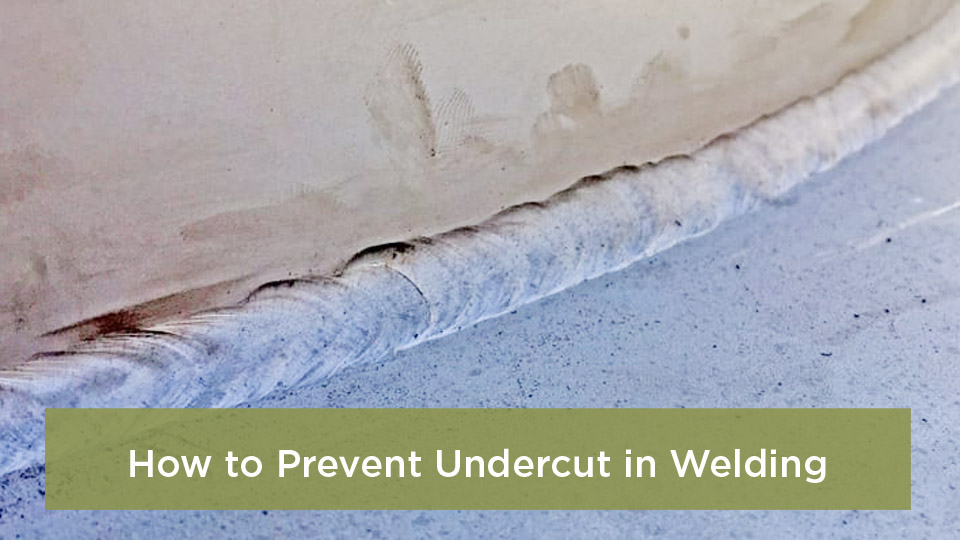
I can’t count how many times I’ve set up for a quick job, pulled the trigger, and found my MIG welder not working the way it should. The machine may be completely dead, feed wire without making an arc, sputter and push the gun backward, or leave a bead full of holes and spatter.
The good news is that many MIG problems come from the setup around the machine rather than a failed power source. A dirty work connection, incorrect polarity, restricted liner, empty gas cylinder, worn contact tip, or mismatched voltage and wire-feed speed can all produce similar symptoms.
The fastest way to find the fault is to work in order: confirm input power, identify which functions still operate, inspect the welding circuit, check wire delivery, verify shielding gas, and only then adjust welding parameters. This guide walks through that process without encouraging unsafe cabinet-level repairs.
Quick Answer
When a MIG welder is not working, first check whether it powers on, feeds wire, releases gas, and energizes the wire. Then inspect the work clamp, polarity, contact tip, drive rolls, spool tension, liner, gas supply, and machine settings. Stop if you find damaged wiring, repeated breaker trips, or an internal fault.
Key Takeaways
- Separate the problem into power, wire feed, weld output, shielding gas, or weld-quality symptoms before changing settings.
- Use the welder’s door chart and owner’s manual instead of treating voltage and wire-feed numbers as universal.
- Solid MIG wire normally uses DCEP polarity; many self-shielded flux-cored wires use DCEN, but the wire label and manual take priority.
- Burnback is commonly linked to restricted feeding, wire speed that is too low for the arc, or holding the gun too close.
- Disconnect input power before removing the gun, liner, drive rolls, or other feed-system parts.
At a Glance
| Time Required | About 15–45 minutes for external checks and consumable service |
| Difficulty | Beginner to intermediate; internal electrical repair requires a qualified technician |
| Tools Needed | Owner’s manual, pliers, contact-tip wrench, clean wire brush, approved leak-detection solution, and scrap metal |
| Cost | Often $0–$40 for cleaning and common consumables; more if a liner, gun, regulator, cable, or internal component has failed |
Image by grassrootsmotorsports
Why MIG Welder Problems Matter
A misbehaving MIG welder is more than an annoyance. Unstable wire delivery, poor electrical contact, incorrect shielding gas, or bad settings can cause porosity, lack of fusion, excessive spatter, burn-through, and inconsistent penetration. A bead can look acceptable on the surface while still failing to fuse properly below it.
Troubleshooting also protects the machine. Continuing to pull the trigger against a blocked liner, overtightened drive rolls, shorted contact tip, or thermal-overload condition can damage consumables and place more strain on the feed motor or power source.
Follow the equipment manufacturer’s instructions and the safety practices in ANSI Z49.1, Safety in Welding, Cutting, and Allied Processes. Z49.1 addresses safety; it does not certify the quality of a structural weld.
Warning: Disconnect the welder from input power before removing the gun, liner, drive rolls, wire guides, or other feed-system parts. Do not remove the machine cabinet or probe internal electronics unless the owner’s manual authorizes the procedure and you are qualified to perform it. Internal capacitors may retain hazardous energy.
Start by Identifying What the Welder Still Does
Before changing voltage or wire speed, observe the machine carefully. These four questions quickly narrow the search:
- Does the machine power on? Check the display, power light, and fan behavior described in the manual.
- Does the wire feed when you press the trigger? Listen for the feed motor and watch the drive rolls without placing your hands near them.
- Does shielding gas flow? Check the flowmeter while the trigger or purge control is active.
- Does the wire become electrically live and strike an arc? Test only after the work clamp and welding area are safely prepared.
Pro Tip: Change one variable at a time. If you adjust voltage, wire speed, gas flow, drive-roll pressure, and technique together, you will not know which change solved—or created—the problem.
Common MIG Welder Problems and Their Fixes
No Power, No Display, and No Fan
If the machine appears completely dead, start outside the welder:
- Confirm the plug is fully seated and the power switch is on.
- Check the branch-circuit breaker, disconnect, or fuse.
- Verify that the receptacle and circuit match the input requirements on the welder’s rating plate.
- Inspect the power cord and plug for cuts, burns, loose blades, or heat damage.
- Reset an external supplementary protector only if the owner’s manual identifies one and explains the procedure.
A tripped breaker is not something to bypass. Repeated trips can indicate an overloaded circuit, damaged cord, incorrect input connection, shorted component, or internal machine fault. Stop using the welder until the cause is identified.
A long or undersized extension cord can also cause voltage drop and weak performance. Use an extension cord only when the welder manufacturer permits it, and follow the specified conductor size and maximum length.
The Fan Runs but the Wire Does Not Feed
If the machine has power but nothing happens at the gun, release the trigger and inspect the external trigger connection. A loose gun plug, damaged trigger lead, or failed trigger switch can prevent the feed motor and gas valve from operating.
If the motor runs but the wire does not move, check for these mechanical problems after disconnecting input power:
- The drive-roll pressure is too low and the rolls are slipping.
- The spool-hub brake is too tight.
- The wire has crossed under another wrap on the spool.
- The wire is not seated in the correct drive-roll groove.
- The contact tip is blocked by burnback or debris.
- The gun cable is sharply bent or coiled too tightly.
- The liner is dirty, kinked, incorrectly sized, damaged, or trimmed incorrectly.
Use only enough drive-roll pressure to feed the wire without slipping. Excessive pressure can flatten solid wire, crush flux-cored wire, shed metal into the liner, and contribute to birdnesting.
Wire Feeds but There Is No Arc
When wire feeds normally but does not create a welding arc, the feed circuit is working but the welding-current path is not complete. Check the following:
- Attach the work clamp—often informally called the ground clamp—to clean, bare metal.
- Clean rust, paint, mill scale, oil, and heavy oxidation from the clamp location.
- Inspect the work lead and its machine connection for looseness, heat damage, or broken strands.
- Confirm that the gun is fully seated and secured in the feeder connection.
- Replace a damaged, loose, badly worn, or burnback-blocked contact tip.
- Verify the polarity connections against the wire label and owner’s manual.
Solid-wire MIG welding of mild steel normally uses direct-current electrode positive, or DCEP. Many self-shielded flux-cored wires use DCEN, but not every wire follows the same rule. The filler-wire label and machine manual are the final authority.
Manufacturer troubleshooting tables also list loose internal connections and power-source faults as possible causes of wire feed without weld output. If the external checks do not restore output, stop and contact an authorized service provider rather than opening the machine.
Erratic Arc, Popping, or Wire Stubbing
An arc that pops, sputters, or repeatedly pushes the gun away usually indicates an imbalance between wire-feed speed and voltage, poor current transfer, or inconsistent wire delivery.
Start with the parameter chart inside the welder or the settings in the owner’s manual. Miller notes that voltage and wire speed depend on material thickness, wire diameter, shielding gas, joint design, and welding position, so one set of numbers cannot be applied to every machine. See the manufacturer’s MIG parameter guidance.
- Wire repeatedly drives into the puddle: Wire-feed speed may be too high for the selected voltage, or voltage may be too low.
- Arc becomes long, harsh, or difficult to control: Voltage may be too high for the wire-feed speed.
- Arc changes as the gun moves: Check the work connection, contact tip, liner, gun cable, and wire-feed consistency.
- Problem appears only after the machine warms up: Inspect duty-cycle and thermal-overload conditions.
Do not chase the sound alone. A stable short-circuit arc often has a steady crackle, but bead shape, fusion, penetration, travel speed, and the machine chart matter more than a “perfect” sound.
Jerky Wire Feed and Birdnesting
Birdnesting is the tangle of wire that forms near the drive rolls when the wire can no longer move freely through the gun. It is usually a symptom of resistance somewhere downstream.
- Disconnect input power.
- Cut and remove the tangled wire without allowing the spool to unwind.
- Remove the contact tip and check whether wire passes through it freely.
- Lay the gun cable as straight as practical.
- Verify the liner diameter and wire size.
- Inspect the liner for kinks, contamination, or incorrect installation.
- Confirm that the drive roll matches both wire diameter and wire type.
- Set spool-hub and drive-roll tension according to the manual.
A smooth V-groove roll is commonly used for solid steel wire, a U-groove roll helps support soft aluminum wire, and a knurled roll is commonly used for tubular flux-cored wire. Use the roll specified by the machine and filler-wire manufacturers.
Keep welding wire clean and dry. Rust, dust, oil, and shop debris can increase drag, contaminate the liner, block the contact tip, and contribute to porosity.
Shielding Gas Does Not Flow
If wire feeds but no gas reaches the nozzle, check the system while the gun trigger or purge function is active:
- Confirm that the correct shielding-gas cylinder is connected and contains pressure.
- Open the cylinder valve using the cylinder and regulator manufacturer’s procedure.
- Read the flowmeter while gas is flowing, not while the system is static.
- Inspect the gas hose for cuts, loose fittings, crushing, or kinks.
- Check the gun connection and any O-rings or seals identified in the manual.
- Remove heavy spatter from the nozzle and gas diffuser.
For light-duty mild-steel MIG welding indoors, Miller recommends 20–25 cubic feet per hour as a common starting range. The correct flow may differ with nozzle diameter, drafts, joint access, gun angle, and the equipment manual.
Use an approved leak-detection solution on external gas fittings. Do not use an open flame. If the hose leaks, replace it rather than patching it.
Porosity or Pinholes in the Weld
Porosity forms when gas becomes trapped in the weld metal. Low shielding flow is only one possible cause. Work through the complete list:
- Empty cylinder, closed valve, incorrect regulator setting, or leaking hose
- Drafts from wind, fans, open doors, or compressed-air tools
- Nozzle held too far from the work
- Nozzle or diffuser blocked by spatter
- Excessive gas flow that pulls surrounding air into turbulent shielding gas
- Wrong shielding gas for the wire or material
- Rusty, wet, oily, or contaminated wire
- Paint, oil, moisture, coating, rust, or mill scale on the joint
- Loose gun connection or damaged gas seals
A 75% argon/25% carbon-dioxide blend is a common all-purpose choice for short-circuit MIG welding mild steel. Pure CO₂ can provide deeper penetration but usually produces a harsher arc and more spatter. Aluminum commonly uses argon, while stainless gas depends on the filler wire, transfer mode, and procedure.
Note: Turning the flowmeter higher does not automatically improve coverage. Excessive flow can create turbulence, waste gas, and draw air into the shielding envelope.
Burnback at the Contact Tip
Burnback occurs when the wire melts and fuses inside or against the contact tip. Common causes include restricted wire feeding, wire-feed speed that is too low for the selected voltage, a contact-tip-to-work distance that is too short, an incorrectly installed liner, excessive spool drag, or a damaged tip.
To correct it:
- Release the trigger and switch off the machine.
- Disconnect input power before servicing the gun.
- Remove the nozzle and damaged contact tip.
- Cut the wire behind the fused section.
- Inspect the liner, gun path, drive-roll pressure, and spool tension.
- Install the correct contact tip for the wire and gun.
- Return to the manufacturer’s baseline voltage and wire-speed settings.
- Maintain the CTWD recommended for the process and gun.
For short-circuit steel MIG, a contact-tip-to-work distance around 1/4 to 1/2 inch is common, but the exact target depends on the process and equipment. Holding the tip too close increases burnback risk; holding it too far away reduces current and shielding effectiveness.
Excessive Spatter
High voltage or excessive wire-feed speed can produce spatter, but they are not the only causes. The Millermatic 211 troubleshooting guide also lists long wire extension, dirty work, poor shielding, dirty wire, and incorrect polarity.
Use this order:
- Verify wire type, polarity, gas, and machine-chart settings.
- Clean the joint and work-clamp location.
- Shorten excessive stick-out.
- Confirm smooth wire feeding.
- Check gas coverage and remove nozzle spatter.
- Adjust voltage or wire speed in small steps while testing on matching scrap.
A push angle of about 5–15 degrees is a common starting technique for solid-wire MIG, but access, joint type, position, penetration needs, and procedure requirements can change the correct angle.
Anti-spatter spray is optional. It can make cleanup easier, but it does not repair a poor setup. Use a product approved for welding, follow its safety data, avoid breathing the mist, and keep excess product away from surfaces that must remain contaminant-free.
The Welder Stops and the Overtemperature Light Comes On
A thermal shutdown normally means the machine has exceeded its duty cycle or cannot cool itself properly. Stop welding and follow the cooling procedure in the owner’s manual. Many machines require the power to remain on so the fan can continue running while the trigger remains released.
- Do not repeatedly pull the trigger while the machine is cooling.
- Keep cooling vents clear of dust, walls, covers, and stored items.
- Check whether ambient temperature or direct sunlight is increasing heat load.
- Reduce output or shorten arc-on time if the job exceeds the rated duty cycle.
- Have a qualified service provider inspect a fan that does not run when the manual says it should.
If the thermal indicator does not reset after the specified cooling period, or if an error code points to a fan, thermistor, motor, or overvoltage fault, stop and arrange authorized service.
Weak Welds, Lack of Fusion, or Burn-Through
A weak-looking bead is not always caused by the machine. Joint design, travel speed, work angle, CTWD, surface condition, and heat input all affect fusion.
- Cold, rope-like bead or poor toe fusion: Heat input may be too low, travel may be too fast, or the arc may not be directed at the leading edge of the puddle.
- Wire piles onto the plate: Wire-feed speed may be too high for the selected voltage.
- Burn-through: Heat input may be too high, travel too slow, gap too large, or material too thin for the current setup.
- Inconsistent penetration: Check line voltage, work connection, gun angle, travel speed, and wire feeding.
For thick joints, increasing voltage alone is not a substitute for suitable joint preparation, bevel angle, root opening, multiple passes, preheat when required, and an approved welding procedure.
Step-by-Step MIG Welder Troubleshooting Guide
- Read the machine indicators. Record warning lights, error codes, fan behavior, and what happens when the trigger is pressed.
- Confirm input power. Check the plug, receptacle, breaker, input-voltage selection, and cord condition.
- Inspect the work circuit. Clamp to clean metal and check the work lead, gun connection, contact tip, and polarity.
- Check wire delivery. Inspect the spool, hub tension, drive-roll type, groove alignment, pressure, gun cable, liner, and tip.
- Verify shielding gas. Check cylinder contents, flow while gas is moving, hose condition, leaks, nozzle cleanliness, and drafts.
- Return to baseline parameters. Use the door chart, owner’s manual, or filler-wire data rather than guessed settings.
- Prepare matching scrap. Use the same metal, thickness, joint condition, wire, gas, and position as the project.
- Change one variable at a time. Make small adjustments and examine arc stability, bead profile, fusion, and penetration.
- Stop at the service boundary. Repeated breaker trips, damaged internal wiring, failed fans, persistent error codes, burning smells, or no output after external checks require qualified service.
MIG Welder Symptom-to-Solution Table
| Issue | Symptoms | Likely Causes | First Checks |
|---|---|---|---|
| No power | No light, display, fan, wire, or gas | Open breaker, loose plug, incorrect input, damaged cord, internal fault | Verify circuit, plug, switch, rating plate, and external protector |
| Wire does not feed | Motor silent or rolls turn without moving wire | Trigger fault, loose gun plug, low roll pressure, tight spool brake, blocked tip | Check trigger connection, spool, rolls, hub tension, liner, and tip |
| Wire feeds but no arc | Wire exits normally but is not energized | Poor work connection, wrong polarity, loose gun, damaged tip, output fault | Clean work-clamp point, inspect leads, verify polarity and gun seating |
| Jerky feed or birdnesting | Wire surges, slips, curls, or tangles at rolls | Kinked liner, blocked tip, wrong roll, excessive pressure, tight hub | Straighten gun and inspect the entire feed path |
| No shielding gas | Wire feeds but no gas is heard or measured | Closed or empty cylinder, blocked nozzle, kinked hose, failed valve | Check flow while trigger or purge is active |
| Porosity | Pinholes, cavities, or worm tracks | Poor gas coverage, contamination, leaks, drafts, wrong gas | Clean metal, verify gas path, check leaks, and block drafts |
| Burnback | Wire fuses inside the contact tip | Restricted feed, low wire speed for voltage, short CTWD, damaged liner | Replace tip, clear feed restriction, and restore baseline settings |
| Excessive spatter | Large droplets around the bead | Parameter mismatch, long stick-out, dirt, gas loss, wrong polarity | Verify setup before making small voltage or wire-speed changes |
| Thermal shutdown | Output stops and temperature light appears | Duty cycle exceeded, blocked vents, high ambient heat, fan fault | Release trigger and follow the manual’s cooling procedure |
Products Worth Considering
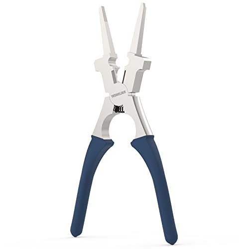
MULTI-FUNCTIONALITY: The welding pliers are meticulously designed for welders who demand precision and efficiency. Perfect for Wire Cutting, Gripping, Tip Removal & Installation, Nozzle Removal & Installation, Inside & Outside Spatter Cleaning, Grooved Tips for Drawing Wire, Hammering and more, this essential tool has you covered.

High-Quality Construction: Our welding pliers, also known as MIG pliers or welpers, are made from premium steel, polished to a smooth finish, and precision processed to ensure sturdiness and durability for extended use.It is reliable welding tools

COMPATIBILITY: Designed for Lincoln Magnum 100L (K530 series) and Tweco Mini/#1 welding torches. This kit is also a direct fit for YESWELDER FLUX-135PRO Old Version/MIG-140DS PRO/YWM-160/MIG-165DS PRO/MIG-185DS PRO/MIG-205DS PRO/MIG-250PRO/MCT-520.
Choosing the Right Equipment and Consumables
Your MIG welder can only perform consistently when the wire, drive system, polarity, shielding gas, contact tip, and machine output are compatible.
Products Worth Considering

20Pcs Contact Tip .023'' Ø0.6mm

Package list: 30 pieces of 0.030 inch mig welder tips.

MIG welding gun accessory kit (0.035") for Miller Millermatic M-25/M-40 and Hobart H MIG gun.
Wire Selection
Mild steel: ER70S-3 and ER70S-6 are common solid-wire classifications. ER70S-6 contains more deoxidizers and is widely used for general fabrication, but the joint should still be cleaned. For many compact machines, 0.030-inch wire is a versatile size, while thinner wire can improve control on thin sheet and larger wire can suit higher-current work. Stay within the machine’s rated range.
Aluminum: ER4043 and ER5356 serve different alloy families and service conditions. Do not choose 5356 simply because the part is described as structural. Match the filler to the exact base alloy, service temperature, required properties, anodized appearance, and approved procedure. Aluminum’s soft wire commonly requires a spool gun, push-pull system, or a carefully configured aluminum feed path. See Miller’s aluminum MIG setup guidance.
Stainless steel: ER308L is commonly used for suitable 304 and 304L stainless applications. Match the filler to both base metals and the required corrosion and mechanical properties. Keep stainless-only brushes and abrasives separate from carbon-steel tools to avoid iron contamination.
Contact Tips, Liners, and Drive Rolls
Start with a contact tip marked for the nominal wire diameter, then follow the gun and wire manufacturer’s instructions. Some aluminum and specialty wires require different clearance or tip construction.
The liner must match the wire material and diameter, reach the required seating points, and be trimmed to the gun manufacturer’s specification. A liner that is too short can leave the wire unsupported near the contact tip, while a liner that is too long can buckle or bind.
Do not assume every drive roll with the correct diameter stamp is suitable. Match both the groove size and groove type to the wire.
Gas Selection
- Mild steel: A 75/25 argon/CO2 blend is a common choice for smooth short-circuit welding with moderate penetration and relatively low spatter. Pure CO2 is another option when the wire and machine support it.
- Aluminum: Argon is commonly used for MIG welding aluminum, with gas and flow selected for the wire, thickness, transfer mode, and equipment.
- Stainless steel: Shielding gas depends on transfer mode and filler-wire guidance. A 90% helium, 7.5% argon, and 2.5% CO2 tri-mix is one established option for suitable short-circuit applications, but it is not the universal gas for every stainless weld.
Machine Recommendations
The original Hobart Handler 140 has been superseded in the current Hobart lineup by the Handler 140EZ, a 120-volt compact machine intended for light shop, repair, and farm work.
The Millermatic 211 family is an example of a portable dual-voltage class of welder. Current model names and specifications change, so compare the machine’s input requirements, output range, duty cycle, supported wire processes, spool-gun compatibility, service network, and owner’s manual through Miller’s current MIG equipment listings.
A new machine does not solve an undersized circuit, poor joint design, incorrect wire, or weak technique. Choose equipment around the material, maximum thickness, available power, expected duty cycle, and required welding procedure.
Safety Considerations
Welding exposes you to electric shock, arc radiation, hot metal, fire, compressed gas, moving feed parts, and hazardous fumes. Follow the machine manual, product safety data, OSHA welding requirements, and applicable workplace rules.
- Wear a welding helmet with a lens shade selected for the process and current, plus safety glasses with side protection underneath.
- Wear dry welding gloves, flame-resistant clothing, and suitable footwear.
- Keep cables out of water, aisles, sharp edges, and hot metal.
- Remove combustible materials and keep suitable fire-extinguishing equipment available.
- Secure shielding-gas cylinders upright with a chain or approved restraint and protect the valve from impact.
- Close the cylinder valve when the system is not in use and relieve downstream pressure as directed by the equipment manufacturer.
- Use local exhaust or other suitable ventilation to keep fumes out of your breathing zone.
- Never use oxygen as ventilation.
Stainless steel welding can produce chromium- and nickel-containing fume. Welding galvanized steel can produce zinc-oxide fume, while painted, plated, or unknown materials may release additional hazardous substances. Remove coatings only by a safe method and use exposure controls selected for the material and workplace.
Do not weld on tanks, drums, pipes, wheels, sealed containers, or parts that may contain flammable, pressurized, or toxic material unless a qualified procedure has made the work safe.
Warning: Troubleshooting does not qualify a safety-critical weld. Structural members, pressure-containing parts, lifting devices, vehicle steering or suspension, roll cages, occupant restraints, and similar components require the correct code, material identification, approved procedure, qualified personnel, and appropriate inspection.
Practical Tips for Better MIG Welding
Prep the joint and clamp location: Remove paint, oil, moisture, heavy rust, and other contamination. Cleaning only the visible seam while clamping onto painted metal can still create an unstable circuit.
Keep the gun cable relaxed: Sharp bends increase liner friction, especially with aluminum and small-diameter wire.
Test the complete setup: Use scrap that matches the project’s alloy, thickness, joint, position, gas, and wire. A bead on a thick flat plate may not predict performance on a thin vertical joint.
Record successful settings: Note the machine, input voltage, wire, gas, material, joint, position, voltage, wire speed, and travel technique.
Inspect consumables before blaming the machine: Contact tips, nozzles, diffusers, liners, and drive rolls are wear items. Replace them when inspection shows damage or when the manual’s limits are reached.
Follow the manual’s maintenance schedule: Dirty environments may require more frequent service. Do not use a fixed monthly interval as a substitute for pre-use inspection and manufacturer guidance.
A stable MIG arc depends on a complete system: correct input power, a low-resistance welding circuit, smooth wire delivery, suitable shielding gas, clean material, compatible consumables, and balanced parameters.
Real-World Applications
For thin auto-body sheet, begin with the welder manufacturer’s chart for the exact wire diameter and material thickness. Use clean solid wire and shielding gas, maintain a short controlled arc, make brief welds when appropriate, and allow cooling to control burn-through and distortion.
For thicker plate, verify that the machine has enough output and duty cycle for the joint. Proper beveling, root access, multiple passes, preheat when required, and cleaning between passes may matter more than simply turning up the voltage.
Repairs to a lawnmower deck, garden cart, bracket, or noncritical fixture may be suitable learning projects when the material is known and the failure would not endanger anyone. A cracked motorcycle frame, trailer coupling, lifting point, pressure vessel, or structural beam belongs in a qualified repair process.
Conclusion
When a MIG welder is not working, avoid changing every control at once. First determine whether the fault involves input power, wire feed, weld output, shielding gas, overheating, or the finished bead. Then inspect the work clamp, polarity, gun connection, contact tip, drive rolls, spool tension, liner, gas system, and machine-chart settings in a safe order.
External setup and consumable problems are often repairable in the shop. Repeated breaker trips, damaged power wiring, persistent error codes, failed cooling components, burning odors, or missing weld output after the basic checks are signs to stop and use an authorized service provider.
Frequently Asked Questions
Why is my MIG welder not feeding wire properly?
Jerky or stopped wire feed can come from a blocked contact tip, kinked gun cable, dirty or damaged liner, incorrect drive roll, poor roll pressure, excessive spool-hub tension, crossed wire, or a loose trigger connection. Disconnect input power before opening the feed compartment or removing feed-system parts.
Why does the wire feed but no arc starts?
Attach the work clamp to clean bare metal, inspect the work lead, verify polarity, seat the gun connection, and replace a damaged or blocked contact tip. If wire still feeds without weld output after the external checks, the machine may need authorized service.
How do I fix porosity in a MIG weld?
Clean the metal and wire, verify the correct shielding gas, check flow while gas is moving, inspect hoses and gun seals for leaks, clean the nozzle and diffuser, block drafts, and maintain the recommended gun distance. Avoid both inadequate flow and excessive turbulent flow.
What settings should I use for MIG welding mild steel?
Use the chart inside your welder, the owner’s manual, or the filler-wire data for the exact metal thickness, wire diameter, shielding gas, joint, and position. Test on matching scrap and change one parameter at a time. A voltage and wire-speed pair from another machine may not transfer accurately to yours.
Why does my MIG welder keep burning back?
Burnback commonly results from restricted feeding, wire speed that is too low for the selected voltage, holding the gun too close, excessive spool drag, an incorrectly installed liner, or a worn contact tip. Replace the damaged tip, clear the feed path, and return to the manufacturer’s baseline settings.
Why is no shielding gas coming from the MIG gun?
Check that the cylinder contains gas and is open, then read the flowmeter while the trigger or purge function is active. Inspect the hose, regulator, gun connection, nozzle, diffuser, and seals. A failed gas valve or control circuit requires qualified service.
Why does my MIG welder shut off while welding?
The machine may have exceeded its duty cycle or entered thermal protection. Release the trigger and follow the manual’s cooling instructions, keeping vents clear. Persistent overheating, a failed fan, or an error that does not reset needs authorized service.
How often should I maintain my MIG welder?
Inspect cables, plugs, the work clamp, gun, nozzle, tip, wire, and gas system before use. Clean or replace feed components when inspection shows contamination or wear, and follow the welder and gun manuals for scheduled maintenance. Dusty or high-use environments require more frequent service.
Sources
- Miller Millermatic 211 Owner’s Manual — maintenance, output, wire-feed, thermal-protection, porosity, spatter, and equipment troubleshooting.
- Miller: Understanding the Basics of MIG Welding for Mild Steel — polarity, gas flow, wire choice, tension, and parameter guidance.
- Lincoln Electric: MIG Problems and Remedies — porosity, feed-system faults, burnback, drive-roll pressure, and consumable problems.
- OSHA 29 CFR 1910.252 — eye protection, protective clothing, ventilation, electric-shock, and welding-safety requirements.
- American Welding Society Safety and Health Resources — ANSI Z49.1 and welding safety fact sheets.
- Miller: How to Successfully MIG Weld Aluminum — aluminum wire feeding, gas, gun configuration, and troubleshooting.