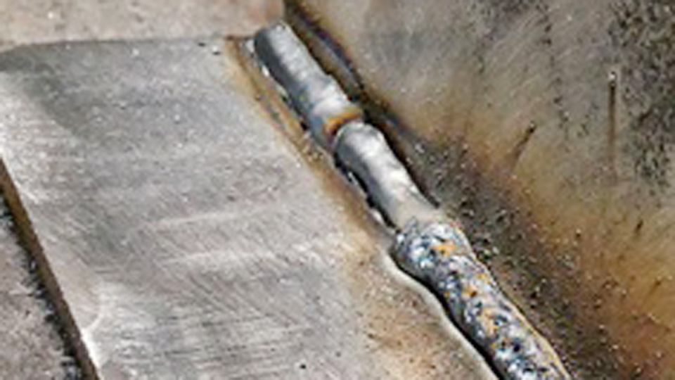
Undercut is the narrow groove that can form beside a weld toe or along a weld root when the arc melts base metal faster than the weld pool fills it. It may look small, but it reduces the effective section of the joint, concentrates stress and can create a place where moisture and corrosion collect.
I’ve seen otherwise solid-looking welds spoiled by undercut in repair and fabrication work. The fastest solution is not to change random controls. You need to find out whether the arc is too aggressive, the travel is too fast, the angle is wrong, or the filler metal is not reaching the weld toes.
Quick Answer
To prevent undercut in welding, follow the approved procedure or machine chart, keep arc length and stickout controlled, aim the heat at the joint instead of one toe, and travel slowly enough for filler metal to fill both edges. Test on matching scrap, inspect every pass, and change one variable at a time.
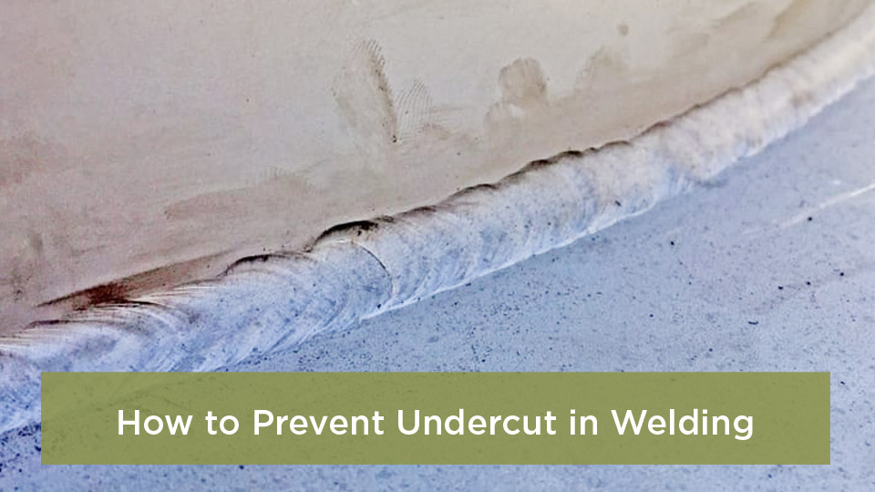
Photo by arcmachines
Key Takeaways
- Excessive current or voltage, fast travel, a long arc, poor angle and inadequate filler placement are the most common direct causes of undercut.
- There is no universal amperage or voltage recipe. Use the WPS, electrode package, wire data sheet or machine chart for your exact setup.
- Watch both weld toes and give the puddle enough time and filler metal to tie in without dwelling so long that you overheat the joint.
- Measure undercut before repairing it. Acceptance depends on the governing code, loading, weld location and project specification.
- Do not grind and reweld structural, lifting, pressure or vehicle-safety joints without an approved repair method.
At a Glance
| Time Required | About 10–30 minutes to inspect the setup and tune it on scrap; longer if a weld needs an approved repair |
| Difficulty | Beginner to intermediate for troubleshooting; advanced for code-controlled repair work |
| Tools Needed | Welder and manual, correct consumables, matching scrap, PPE, wire brush or grinder, good lighting and a weld gauge when acceptance must be measured |
| Cost | Usually low if you already own the equipment; normal costs include scrap, cleaning discs and welding consumables |
What Is Undercut in Welding?
Undercut is an unfilled groove melted into the base metal beside the weld toe or at the weld root. The latest AWS A3.0 welding terminology standard provides the industry’s standardized language for welding discontinuities and processes.
Toe undercut appears where the face of the weld meets the base metal. You can usually see it after removing slag and spatter. Root undercut forms at the root side of a groove weld and may be difficult or impossible to see from the face of the joint.
Undercut is not simply an unattractive bead. It is missing base-metal section beside a weld, so it must be evaluated by location and measured depth rather than appearance alone.
Undercut vs. Other Weld Discontinuities
| Discontinuity | What It Looks Like | Main Difference |
|---|---|---|
| Undercut | A groove beside the toe or root | Base metal was melted away and left unfilled |
| Underfill | The weld face or root sits below the surrounding surface | The weld itself lacks enough deposited metal |
| Overlap | Weld metal rolls beyond the toe | Metal extends over the base without proper fusion |
| Incomplete fusion | The weld metal does not fuse fully with the base metal or previous pass | The surfaces may touch but are not properly joined |
Why Undercut Matters
Undercut reduces the effective cross-section of the base metal and creates a sharper transition at the weld toe. That transition can become a stress concentration, especially where the joint sees repeated loading, vibration, bending or tension.
The groove may also hold water, salt or dirt. That makes undercut especially undesirable on trailers, gates, outdoor machinery and equipment exposed to road spray or weather.
Note: Visible undercut is not automatically acceptable or automatically rejectable. Measure it and compare it with the code, drawing, WPS and contract that govern the job. For personal projects with no formal acceptance standard, correcting obvious undercut is the safer quality choice.
Does AWS D1.1 Allow Any Undercut?
AWS D1.1/D1.1M:2025-AMD1 establishes structural-steel fabrication, inspection and acceptance requirements. The standard does not support the blanket claim that every trace of undercut fails every structural weld.
The allowable amount can depend on the joint, member, loading direction, weld orientation and applicable table or clause. The edition named in the project documents controls, even when a newer edition has been published. When the work is inspected, ask the welding inspector or engineer which acceptance criteria apply before removing metal or adding a repair bead.
Common Causes of Welding Undercut
Undercut normally appears when the arc removes more base metal from an edge than the weld pool replaces. The cause may be excessive arc energy, inadequate deposition at the toe or poor control of the puddle.
| Likely Cause | What You May See | First Correction to Try |
|---|---|---|
| Current or voltage too high | A wide, flat or deeply washed bead with grooves at one or both toes | Return to the approved range and reduce the aggressive setting in a small step |
| Travel speed too fast | A narrow bead that does not fill the toes | Slow enough for the puddle to wet both edges |
| Arc too long | Wide, wandering arc, spatter and poor edge control | Shorten the arc while maintaining a stable puddle |
| Incorrect work angle | Undercut mainly on one side of the joint | Redirect the arc toward the joint center or the colder member |
| Excessive travel angle | The arc outruns or pushes the puddle away from a toe | Reduce the travel angle and keep the puddle under the arc |
| Insufficient filler or deposition | The edges melt but remain starved | Add filler more consistently or correct wire-feed and travel balance |
| Incorrect stickout or electrode extension | Unstable arc, changing penetration or poor bead profile | Maintain the range specified for the process and consumable |
| Poor fit-up or joint preparation | The arc falls into a gap or attacks a sharp edge | Correct the gap, alignment, bevel or tack spacing before welding |
| Arc blow or unstable wire feeding | The arc deflects or deposition changes during the bead | Check lead placement, work connection, cable routing, contact tip and feed system |
Rust, oil, paint and heavy mill scale are not always the direct cause of undercut, but they can destabilize the arc, interfere with fusion and make the puddle harder to read. Clean metal also makes inspection much easier.
Undercut Risks by Welding Process
Stick Welding (SMAW)
Stick welding is sensitive to current, arc length, electrode angle, manipulation and travel speed. Miller groups these controls as the main elements of SMAW technique and notes that a long arc or excessive travel speed can contribute to undercut.
Keep the arc close and consistent. A practical starting point is an arc length near the diameter of the electrode’s metal core, unless the electrode manufacturer or WPS says otherwise. Point the electrode so the arc reaches both sides of the joint instead of digging into one toe.
Do not treat 120 or 130 amps as a universal maximum for a 1/8-inch E7018 electrode. The correct current depends on the brand, position, joint, polarity and procedure. Use the range printed on the package or data sheet, then fine-tune on matching scrap.
Pro Tip: In a vertical-up fillet, make a controlled move across the center and a brief pause at each toe. Watch the edge fill before moving away, but avoid a wide weave or long pause that overheats the plate.
MIG Welding (GMAW)
GMAW undercut often comes from excessive voltage, travel that outruns the puddle, incorrect gun angle or an imbalance between wire-feed speed and voltage. Wire-feed speed largely affects current and deposition in a constant-voltage system, while voltage changes arc length and bead shape. Adjusting one may require a coordinated adjustment to the other.
Keep contact-tip-to-work distance consistent. If stickout changes while you weld, current, penetration and deposition can change with it. Check the gun liner, drive-roll pressure and contact tip when the bead changes even though your hand speed remains steady.
A push angle of roughly 5–15 degrees works for many solid-wire applications, but it is not a rule for every transfer mode, wire or position. Follow the wire manufacturer and WPS when they specify a different technique.
Flux-Cored Welding (FCAW)
FCAW was missing from the original article even though it is common in structural and heavy-fabrication work. Undercut can appear when voltage is too high, travel is too fast, the work angle favors one plate, or electrode extension is outside the wire manufacturer’s range.
Many flux-cored wires use a drag technique, but the correct travel angle and extension depend on whether the wire is self-shielded or gas-shielded. Remove slag between passes so you can see the true weld toes before continuing.
TIG Welding (GTAW)
GTAW gives you direct control of arc length, heat and filler addition, but it can undercut when you hold too long without adding filler, use excessive amperage, lean the torch too far or let the arc length grow.
Keep the arc compact and place the filler at the leading edge of the puddle. Maintain a steady rhythm so each addition replaces the metal melted at the toes. As the work heats up, reduce pedal pressure or machine output rather than increasing travel speed until the filler can no longer keep up.
Use the tungsten type and diameter recommended for the current range and power source. Lanthanated and ceriated electrodes are common non-thoriated choices. If your procedure requires thoriated tungsten, use dedicated dust-controlled grinding and follow workplace handling rules because grinding can create thorium-containing dust.
Step-by-Step Guide to Prevent Undercut
Warning: Do not practice settings on a structural member, pressure component, lifting point, suspension part or safety-critical vehicle repair. Use matching scrap, and follow an approved WPS or qualified repair procedure when the joint is code-controlled.
Step 1: Check the Procedure and Consumable Data
Before adjusting the welder, check the drawing, WPS, machine chart, electrode package or wire data sheet. Confirm:
- The welding process and polarity
- Electrode or wire classification and diameter
- Shielding gas and flow range when applicable
- Material type and thickness
- Joint design and welding position
- Permitted current, voltage, wire speed and travel technique
- Preheat and interpass-temperature requirements
The approved procedure takes priority over generic settings from an article or video.
Step 2: Prepare and Fit the Joint
Remove paint, oil, moisture, heavy rust and loose scale far enough from the joint to keep contaminants out of the weld pool. Use a clean wire brush, flap disc or other method suitable for the metal.
Fit the parts to the specified root opening, alignment and bevel. Do not automatically apply a 30-degree bevel to every plate over 1/4 inch. Groove angle, root face and root opening must suit the joint design and procedure.
For unequal-thickness joints, direct more heat toward the thicker member while still allowing the weld to tie into the thinner edge. Pointing the arc equally at both pieces can overheat the thin side before the thick side reaches proper fusion.
Step 3: Choose the Correct Filler and Electrode Size
Match the filler classification to the base metal and procedure. ER70S-6 and E7018 are common choices for some mild-steel applications, but they are not interchangeable answers for every steel.
Stainless filler must match the stainless grade and service. ER308L is commonly used for certain 304-series applications, while other alloys may require ER309L, ER316L or another classification. Aluminum filler selection also depends on the base alloy, strength, crack sensitivity, corrosion service and finishing requirements.
A smaller electrode or wire can help control deposition on thin material, but it does not replace correct joint design and parameter selection.
Step 4: Establish a Baseline on Matching Scrap
Use scrap with the same material, thickness, joint type and position as the actual work. Set the machine within the approved or manufacturer-recommended range and run a short test bead.
Clean the bead and inspect both toes. Listen for an even arc and watch whether the puddle reaches the edges without washing them away.
Change only one main variable at a time. If you alter voltage, wire speed, angle and travel speed together, you will not know which change helped.
Step 5: Control Work Angle, Travel Angle and Distance
Work angle aims the arc across the joint. On an equal-thickness T-joint, the starting work angle is usually near the center of the corner. On a butt joint, direct the arc toward the joint line. Adjust toward the colder or thicker side when the pieces are unequal.
Travel angle tilts the electrode or gun along the welding direction. Keep it modest unless the procedure calls for something different. An excessive angle spreads the arc and can pull the puddle away from one toe.
Arc length, stickout and electrode extension must stay consistent. A long SMAW or GTAW arc spreads heat and reduces control. In wire welding, changing contact-tip-to-work distance changes the electrical and deposition conditions.
Step 6: Balance Heat, Travel and Deposition
Watch the leading edge of the weld pool rather than staring at the arc. You should see the puddle reach each toe and leave a smooth transition into the base metal.
- If both toes wash away, reduce excessive heat or voltage within the approved range.
- If the bead is narrow and the toes remain empty, reduce travel speed.
- If only one toe undercuts, correct the work angle before changing the machine.
- If the arc melts the edge faster than TIG filler fills it, add filler more consistently or reduce heat.
- If MIG deposition is too low for the arc width, use the machine chart to rebalance wire-feed speed and voltage.
Step 7: Adapt to the Welding Position
Gravity changes puddle behavior. Horizontal fillets tend to undercut the upper toe when the work angle or travel speed is wrong. Vertical-up welds need controlled sidewall pauses. Overhead welds need a compact puddle and close arc control.
Do not slow down blindly. Excessively slow travel can increase heat input, create an oversized bead or cause burn-through on thin material. The goal is enough time to fill the toe, not maximum dwell time.
Step 8: Clean and Inspect Every Pass
Remove slag, spatter and soot before evaluating the bead. Use bright lighting from more than one angle. A shadow can make a smooth transition look like a groove, while slag can hide real undercut.
When acceptance matters, use a suitable weld gauge or depth gauge and record the location and dimension. Compare the result with the project’s governing acceptance criteria.
How to Diagnose Undercut by Appearance
| What You See | Most Likely Cause | Best First Check |
|---|---|---|
| Grooves along both toes | Excessive arc energy, long arc or travel that is too fast for deposition | Verify current or voltage, shorten the arc and watch puddle fill |
| Undercut on one side only | Incorrect work angle or unequal heat distribution | Recenter the arc or favor the thicker member |
| Undercut near the end of the weld | Heat buildup, increased travel or reduced filler near the finish | Reduce output gradually and maintain filler through the crater |
| Intermittent undercut with changing arc sound | Feed problem, changing stickout, poor work connection or arc blow | Inspect cables, work clamp, contact tip, liner and drive system |
| Upper-toe undercut in a horizontal fillet | Arc aimed too high or insufficient pause at the upper toe | Correct the work angle and support the upper edge with the puddle |
| Vertical weld with washed-out sides | Excessive current, wide weave or slow cross-joint movement | Reduce the weave width and use controlled toe pauses |
How to Inspect and Measure Undercut
Start with visual inspection after the weld has cooled enough to handle safely and all slag or loose residue has been removed. Look along the toe rather than directly down at the face. Side lighting makes shallow grooves easier to identify.
A weld gauge can help determine whether the groove is measurable and how deep it is. Measure the actual discontinuity rather than judging it by color, spatter or the width of a shadow.
Visual inspection only reveals accessible surfaces. Root-side undercut inside pipe or a closed joint may require the inspection method specified by the job, such as radiographic, ultrasonic or another approved examination.
Do not use a grinder to “check” the depth before determining whether grinding is allowed. Grinding changes the discontinuity and may remove additional base metal.
How to Fix Undercut Safely
The repair depends on the weld’s service and the applicable acceptance criteria. A shallow groove on a noncritical practice coupon is not handled the same way as undercut on a crane component, structural connection or pressure weld.
Products Worth Considering

1200PCS Staples + 40PCS Rods — All-in-One Repair Kit — 1200PCS hot staples in 6 types (wave, flat, inside/outside corner) plus 40PCS plastic welding rods give you enough material to fix bumpers, dashboards, trash cans, and more without running out mid-project. Heats to approx. 400°C/752°F in about 3 seconds, embedding staples deep for a hold that outlasts the surrounding plastic.

UL CERTIFIED: Our Plastic Welder, the factory, and the process have been tested, approved, and Certified by Underwriters Laboratories (UL). Safety is our number one priority
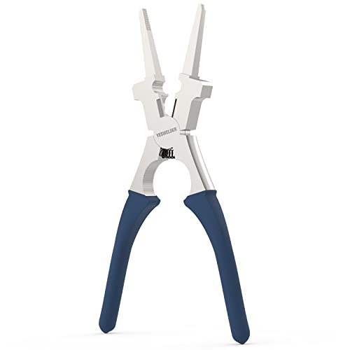
MULTI-FUNCTIONALITY: The welding pliers are meticulously designed for welders who demand precision and efficiency. Perfect for Wire Cutting, Gripping, Tip Removal & Installation, Nozzle Removal & Installation, Inside & Outside Spatter Cleaning, Grooved Tips for Drawing Wire, Hammering and more, this essential tool has you covered.
For Practice Welds and Noncritical Personal Projects
- Stop and identify the cause before adding another bead.
- Clean the groove and surrounding weld toe.
- Confirm that the base metal is sound and has not become excessively thin.
- Feather sharp starts, stops or high spots only as needed without digging deeper into the plate.
- Refill the area using corrected heat, angle, travel and filler placement.
- Clean and inspect the completed repair again.
For Structural, Pressure or Safety-Critical Welds
- Mark the location and measure the discontinuity.
- Compare it with the governing acceptance criteria.
- Notify the responsible inspector, supervisor or engineer when required.
- Use the approved repair procedure, including any specified excavation, preheat, consumable and interpass controls.
- Reweld with qualified parameters and a qualified welder when required.
- Repeat the specified inspection or nondestructive examination.
Warning: Grinding until the groove disappears can reduce the base-metal thickness and make the joint weaker. Do not blend or weld over a rejectable discontinuity until you know what the governing repair procedure requires.
How to Set the Welder Without Guessing
Published numbers such as “18–20 volts” or “90–120 amps” may work for one combination of machine, consumable, gas, position and joint but fail on another. Use them only when they come from the applicable WPS or the manufacturer’s chart for your exact setup.
| Process | Main Controls | Signs the Arc Is Too Aggressive | Safer Tuning Method |
|---|---|---|---|
| Stick (SMAW) | Current, arc length, angle, travel and electrode manipulation | Wide arc, heavy spatter, washed toes or uncontrollable puddle | Use the electrode package or WPS range, then tune current and arc length on scrap |
| MIG (GMAW) | Voltage, wire-feed speed, stickout, gas, transfer mode and travel | Overly flat bead, long arc, poor toe fill or excessive spatter | Start from the machine chart and rebalance voltage and wire speed rather than changing one blindly |
| Flux Core (FCAW) | Voltage, wire-feed speed, electrode extension, polarity and travel angle | Washed upper toe, long arc or inconsistent slag coverage | Use the wire data sheet and maintain its specified extension and travel technique |
| TIG (GTAW) | Amperage, arc length, torch angle, travel and filler rate | Wide puddle, melting edges and filler that cannot keep up | Shorten the arc, reduce heat as the work warms and maintain filler additions |
Pro Tip: Save successful settings with the material, thickness, joint, position, consumable, gas and machine name. A number without that context is not a repeatable welding procedure.
Products Worth Considering

🧲 Sticks to Toolboxes & Welders – Heavy-duty magnetic welding chart adheres to metal surfaces like your welding table, toolbox, or wall for instant reference while working.


3 Pack of 3 3/8 x 7 inch reference Charts printed on plastic
Preventing Undercut on Different Materials and Positions
Thin Steel
Use a smaller wire or electrode when appropriate, short weld segments and controlled heat. Avoid pointing the arc directly at a free edge. Pulse GMAW or GTAW may improve control when the machine and procedure support it, but neither process automatically prevents undercut.
Thick Steel
Use the specified groove preparation and multi-pass sequence. Clean every pass and position each bead so it supports the next one. An excessively wide weave can wash out the sidewalls, so stay within the procedure’s permitted bead width.
Stainless Steel
Control heat input and use the filler specified for the alloy and service. Keep the arc focused and maintain steady filler placement. Stainless steel’s lower thermal conductivity can cause local heat to build quickly near the weld.
Aluminum
Remove oxide with the approved cleaning method and keep dedicated tools free from steel contamination. Use the correct AC balance, tungsten, filler and gas for the setup. Aluminum’s high thermal conductivity often requires strong initial heat, followed by reduced output as the work warms.
Vertical and Horizontal Welds
For vertical-up welding, keep the puddle small and use brief toe pauses with a quick, controlled transition across the center. For horizontal fillets, watch the upper toe carefully because gravity pulls the puddle downward.
Common Mistakes and Better Corrections
- Mistake: Lowering every setting at once. Better correction: Return to a known baseline and change one variable at a time.
- Mistake: Slowing down without watching the puddle. Better correction: Slow only until both toes fill, then maintain that travel speed.
- Mistake: Using a wide weave to hide a groove. Better correction: Fix heat, angle and filler placement before increasing bead width.
- Mistake: Holding a long arc to see better. Better correction: Improve lighting and helmet settings while keeping the correct arc length.
- Mistake: Aiming equally at unequal thicknesses. Better correction: Bias heat toward the thicker or colder member.
- Mistake: Assuming a clean-looking weld passes inspection. Better correction: Measure the discontinuity and apply the governing criteria.
- Mistake: Grinding first and asking questions later. Better correction: Determine whether repair is required and approved before removing metal.
Safety Considerations
Welding and grinding expose you to ultraviolet radiation, burns, fumes, electrical hazards, fire, noise and flying particles. OSHA requires suitable eye and face protection for arc welding and provides different filter-shade guidance for different operations and electrode sizes. Do not assume one shade range fits every process. Review the applicable guidance in OSHA 29 CFR 1910.252 and follow the helmet manufacturer’s instructions.
Wear flame-resistant clothing, welding gloves, safety glasses under the helmet and suitable hearing and respiratory protection based on the hazard assessment. Keep cables away from passageways and remove combustible materials from the hot-work area.
Use local exhaust ventilation to keep fumes away from your breathing zone. A respirator does not replace ventilation, and workplace respirator use may require medical evaluation, fit testing and a written program. OSHA’s welding hazards and solutions guidance covers fumes, ultraviolet radiation, burns, shock and other hazards.
Do not casually weld inside a tank, vessel or other confined space. Confined-space work may require atmospheric testing, mechanical ventilation, an attendant, a rescue plan and equipment located outside the space.
Before welding galvanized, painted, plated or unknown metal, identify the coating and control the fumes using the applicable procedure. Never use oxygen for ventilation.
Connect the work lead to clean metal as close to the weld as practical. A poor work-current connection can cause an erratic arc. Protective equipment grounding is a separate electrical-safety requirement and must follow the welder manufacturer’s instructions.
Tradeoffs When Correcting Undercut
| Correction | Benefit | Possible Tradeoff |
|---|---|---|
| Reduce excessive heat | Limits edge wash and improves puddle control | Too much reduction can cause incomplete fusion |
| Reduce travel speed | Gives filler time to reach the toes | Travel that is too slow raises heat input and bead size |
| Pause briefly at the toes | Improves sidewall fill in vertical or wide joints | Long pauses can overheat the edge |
| Shorten the arc or stickout | Improves arc focus and consistency | Going outside the specified range can cause sticking or unstable transfer |
| Use a small controlled weave | Helps place metal across a wider joint | Excessive width can increase heat and violate the WPS |
| Improve joint preparation | Provides predictable access and fit-up | Adds preparation time before welding |
Where Undercut Control Is Most Important
Structural steel: Buildings and other structural-steel work may reference AWS D1.1. Use the edition and acceptance criteria named in the project documents.
Bridges: Bridge welding commonly follows AASHTO/AWS D1.5 rather than automatically using AWS D1.1. Do not transfer acceptance limits from one code to another.
Pipelines and pressure systems: Follow the approved WPS and governing pipeline or pressure code. Do not assume every joint should use a 6010 root and 7018 fill.
Lifting and heavy equipment: Crane parts, buckets, booms and lifting attachments see high stress and vibration. Repairs should follow the equipment owner’s engineering and inspection requirements.
Trailers and vehicle parts: A gate or decorative frame is not the same as a hitch, suspension bracket or frame repair. Safety-critical vehicle welds require appropriate design, material identification and qualified repair methods.
DIY projects: Even when no code applies, eliminating visible undercut improves appearance, corrosion resistance and confidence in the joint. Practice on scrap until you can produce smooth, consistent toes.
Conclusion
You prevent undercut by balancing heat, travel speed, arc length, angle and filler deposition rather than relying on one magic setting. Start with the WPS or manufacturer’s data, prepare the joint properly and run a test bead on matching scrap. Watch both toes, keep your distance consistent and adjust one variable at a time.
After welding, clean and inspect every pass. Measure any groove when acceptance matters, and do not grind or reweld a code-controlled joint without the required repair procedure. These habits reduce rework and produce smoother, stronger and more repeatable welds.
Frequently Asked Questions
What is undercut in welding?
Undercut is an unfilled groove melted into the base metal beside a weld toe or at the weld root. It can reduce the effective section of the joint and create a stress concentration.
What causes undercut in welding?
Common causes include excessive current or voltage, fast travel, a long arc, incorrect work or travel angle, inconsistent stickout and inadequate filler-metal placement at the weld toes.
How do I fix undercut in a weld?
First measure and evaluate the groove. On noncritical work, clean the area and refill it using corrected settings and technique. For structural, pressure or safety-critical welds, follow the approved repair procedure and repeat the required inspection.
Does slowing down always prevent undercut?
No. Slowing down helps when travel is outrunning deposition, but excessive dwell increases heat input and may cause an oversized bead or burn-through. Watch the puddle and slow only enough to fill both toes.
Which welding process is most prone to undercut?
SMAW, GMAW, FCAW and GTAW can all produce undercut. The risk depends more on heat, travel, angle, arc length, electrode extension and filler placement than on the process name alone.
Is any undercut allowed under AWS D1.1?
Acceptance depends on the applicable AWS D1.1 edition, weld location, loading and measured dimensions. Use the criteria specified by the project rather than assuming all undercut passes or fails.
Why is undercut appearing on only one side of my weld?
One-sided undercut usually points to an incorrect work angle, unequal plate thickness, gravity or arc deflection. Recenter the arc or direct more heat toward the thicker or colder member before changing several machine settings.
Sources
- American Welding Society: AWS D1.1/D1.1M:2025-AMD1 — structural-steel qualification, inspection and acceptance framework
- American Welding Society: AWS A3.0M/A3.0:2025 — current welding terminology and definitions
- OSHA 29 CFR 1910.252 — welding eye protection, clothing, ventilation and confined-space requirements
- OSHA Welding, Cutting and Brazing Hazards and Solutions — fumes, radiation, burns, shock and workplace controls
- Miller: Five Steps to Improving Stick Welding Technique — current, arc length, angle, manipulation and travel-speed guidance
- Miller: Reduce Weld Rework With These Tips — travel speed, angle, stickout, wire feeding and toe-fusion troubleshooting