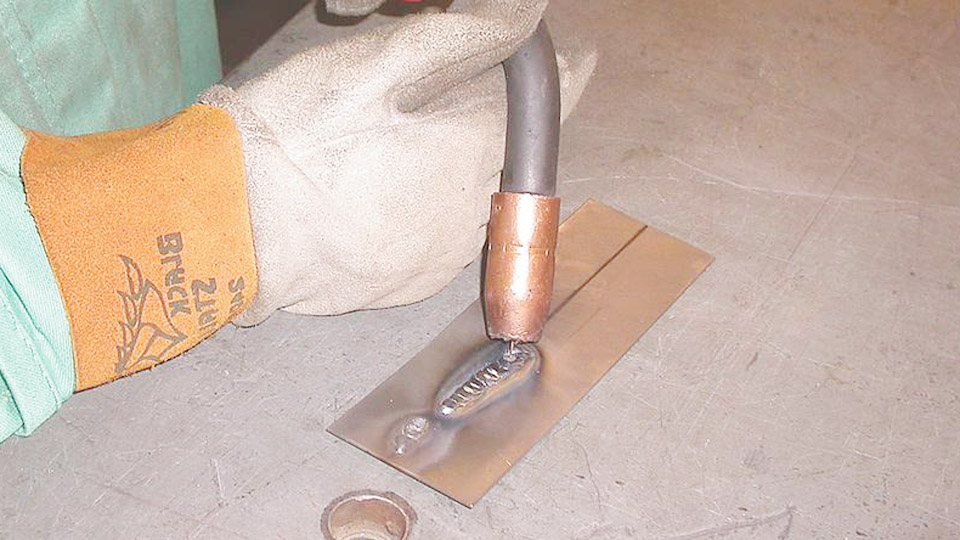
When your MIG welder wire feeds but no arc forms, the trigger and feed motor are doing part of their job, but welding current is not completing the circuit through the wire and workpiece. The fastest checks are the work clamp, weld-cable connections, gun power connection, contact tip, polarity, process selector, and machine fault lights.
I first ran into this while tacking mild-steel tubing for a garage project. The wire rolled out normally, but there was no spark when it touched the steel. The problem was not metal thickness or shielding gas. The work clamp was sitting on a painted area and could not make a reliable electrical connection.
A totally dead arc is different from an arc that sputters, pushes the gun back, burns into the contact tip, or produces a porous weld. That distinction helps you avoid spending time adjusting gas and wire speed when the real problem is an open or disabled weld-output circuit.
Quick Answer
If the wire feeds but there is no spark at all, start with the work clamp and both weld-cable connections. Then check the gun power connection, contact tip, polarity jumpers, process or gun selector, and fault lights. Gas, liner condition, and voltage settings matter, but they usually cause poor welding rather than a totally dead arc.
Key Takeaways
- Wire feeding proves that the trigger and feed motor respond, but it does not prove that welding voltage is reaching the wire.
- A poor work-clamp connection, loose weld cable, loose gun power pin, damaged contact tip, or disabled output is more likely than a gas problem.
- Incorrect voltage and wire speed normally cause stubbing, popping, burnback, or an unstable arc rather than no spark at all.
- Use the polarity and process specified for the exact wire. Solid-wire GMAW commonly uses DCEP, while many self-shielded wires require DCEN.
- Stop after the safe external checks if the welder still has no output. Internal contactor, rectifier, inverter, and control-board tests belong to a qualified service technician.
At a Glance
| Time Required | About 10 to 30 minutes for safe external checks |
| Difficulty | Beginner to intermediate; internal electrical repair requires a qualified technician |
| Tools Needed | Welding PPE, wire brush or grinder, insulated hand tools, spare contact tip, scrap metal, and the machine’s owner’s manual |
| Cost | Often no cost if the problem is dirt, a loose connection, a selector setting, or a protection reset; replacement parts and professional repairs vary |
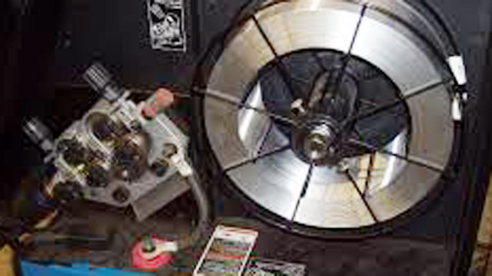
Image by gowelding
Why Does My MIG Welder Feed Wire but Not Arc?
A MIG gun performs several functions when you pull the trigger. Depending on the machine, it starts the feed motor, opens the gas valve, and commands the power source or contactor to energize the electrode wire. The feed motor can still run when the welding-current circuit is open, loose, disabled, overheated, or faulty.
The normal current path runs from the power source through the gun cable, power pin, contact-tip holder, contact tip, electrode wire, workpiece, work clamp, and work cable back to the welder. One failed connection in that path can leave you with moving wire and no electrical arc.
A representative Miller MIG welder troubleshooting table lists the work clamp, loose connections, contact tip, polarity connections, and gun-to-feedhead connection as checks when there is no weld output but the wire still feeds.
Note: Welders often say “ground clamp,” but “work clamp” is more accurate. The work lead carries welding current back to the power source. The protective equipment ground in the power cord is a separate electrical-safety connection.
Products Worth Considering

Package list: 30 pieces of 0.030 inch mig welder tips.

20Pcs Contact Tip .023'' Ø0.6mm

1. Package Includes 30 Premium Quality .023” (Ø0.6mm)welding Tips.
1. Check Protection Lights and Reset the Machine Safely
Warning: Do not open the welder’s case, touch internal terminals, bypass a safety switch, or probe live internal voltage unless you are trained and authorized to service welding power sources. Dangerous voltage may remain inside some machines after input power is disconnected.
Look at the display and indicator lights before changing anything. An over-temperature, short-circuit, motor, trigger, input-voltage, or communication fault may disable weld output even though part of the machine still responds.
If an over-temperature light is on, release the trigger and follow the cooling procedure in the owner’s manual. Many machines require the fan to keep running until the thermostat resets. Do not repeatedly cycle the trigger or bypass the protection.
After the light clears, switch the welder off and disconnect input power before touching the gun connection, polarity terminals, contact tip, work cable, or other electrical connections. Close the cylinder valve if you will disconnect gas equipment.
2. Inspect the Work Clamp and Work Cable
The work clamp completes the welding-current circuit. It must grip clean, bare metal and make firm metal-to-metal contact. Paint, rust, mill scale, oil, adhesive, anodizing, powder coating, and loose jaws can add enough resistance to weaken or stop the arc.
- Attach the clamp directly to the workpiece when practical.
- Clean a small clamp area to bright metal with a wire brush or grinder.
- Place the clamp as close to the weld as practical.
- Do not rely on a rusty table, painted fixture, hinge, bearing, chain, vehicle body part, or loosely bolted assembly to carry welding current.
- Inspect the clamp jaws, spring, cable lug, machine terminal, and full visible cable length.
- Replace a clamp or cable that is burned, badly corroded, loose, undersized, or damaged.
OSHA’s arc-welding requirements state that work-circuit connections must be mechanically strong and electrically adequate for the welding current.
3. Check the Gun Power Connection and Weld Cables
If the work side is good, inspect the gun side. The trigger wires can operate the feed motor while a separate high-current connection remains loose or disconnected.
With the welder switched off and unplugged, check the following:
- Make sure the gun power pin or Euro connector is fully seated.
- Tighten the gun-retaining knob, thumbscrew, or connector collar according to the manual.
- Confirm that the gun end is seated against the feedhead or power block.
- Inspect the gun cable for crushed areas, burned insulation, sharp bends, or a loose strain relief.
- On a separate wire feeder, check the weld cable and interconnecting cable at both ends.
- Check external positive and negative output connectors for looseness, heat damage, or an incomplete twist-lock connection.
If you can feed wire and hear a click inside the machine but the wire remains electrically dead, a loose weld cable, failed contactor connection, damaged gun power conductor, or internal output problem becomes more likely.
4. Inspect the Contact Tip and Tip Holder
The contact tip transfers welding current to the moving electrode wire. Remove the nozzle and contact tip only after switching the machine off and disconnecting input power.
Check for:
- Wire fused to the tip after burnback
- A loose contact tip
- A cracked, overheated, or badly eroded tip
- A damaged diffuser or contact-tip holder
- Heavy spatter bridging the nozzle and tip area
- A tip that does not match the wire diameter and gun system
A blocked tip usually restricts wire feeding. An oversized or worn tip more often causes erratic current transfer and an unstable arc. However, a loose tip, damaged holder, or failed electrical connection in the gun can leave the wire without reliable weld current.
Pro Tip: Install a known-good contact tip that matches the wire and gun. It is a faster test than trying to judge a worn tip by appearance alone.
5. Verify Polarity, Process Mode, and Gun Selection
For solid-wire GMAW on steel, the gun is commonly connected to electrode positive and the work lead to negative. This is DCEP, also called reverse polarity. Many self-shielded flux-cored wires use DCEN, but some flux-cored products require DCEP. Always follow the label on the wire spool and the machine’s polarity diagram.
Loose polarity jumpers or output connectors can interrupt the welding circuit. Wrong polarity usually produces poor arc characteristics, excess spatter, or poor penetration rather than a completely dead machine, but it still needs correction.
On a multiprocess or digitally controlled welder, also confirm:
- The machine is in MIG/GMAW or the required CV wire mode.
- The correct standard gun or spool gun is selected.
- The output or contactor is enabled.
- The machine is not in jog, purge, setup, or demonstration mode.
- A remote-control setting is not preventing local weld output.
- The wire feeder is connected to the correct output receptacle.
Some machines intentionally disable weld output while jogging wire. Others switch into a jog mode after the trigger is held without an arc. Use the exact model and serial-number manual rather than assuming every control works the same way.
6. Verify Input Power and Welding Parameters
Make sure the supply voltage and circuit match the welder’s nameplate and manual. A loose plug, tripped breaker, incorrect input connection, low line voltage, or undersized extension cord can reduce output or trigger a protection fault.
Do not assume every machine is simply “110V or 220V.” Common nominal systems include 120V, 208V, 230V, and 240V, and some machines require internal or external input configuration.
Voltage and wire-feed speed matter after electrical output is present:
| Observed Behavior | What It Usually Suggests | First Action |
|---|---|---|
| Wire touches clean steel with no spark at all | Open, loose, disabled, or failed weld-output circuit | Check work clamp, cables, gun connection, tip, polarity, selectors, and fault lights |
| Wire repeatedly pushes into the work and pops | Voltage too low for WFS, excessive WFS, poor work connection, or excessive stickout | Use the door chart, shorten stickout, and adjust voltage or WFS on scrap |
| Wire burns back into the contact tip | WFS too low, voltage too high, feed restriction, or contact tip too close | Replace the damaged tip, inspect feed resistance, and reset parameters |
| Arc is long, harsh, or unstable | Voltage too high, poor current transfer, loose connection, or incorrect gas | Check connections and use the machine’s recommended starting settings |
Start with the parameter chart inside the machine or the manufacturer’s manual. Material thickness, wire diameter, joint design, position, shielding gas, and machine calibration all affect the correct settings. Test on matching scrap before welding the actual part.
7. Check Shielding Gas After the Arc Is Restored
Shielding gas protects the molten weld pool from oxygen, nitrogen, and moisture in the surrounding air. It affects porosity, oxidation, spatter, transfer mode, and overall arc behavior. However, a missing gas supply normally does not explain wire feeding with absolutely no electrical spark.
For short-circuit MIG welding on mild steel, 75% argon and 25% CO2 is a common gas. Many small-shop machines list about 20 to 25 cubic feet per hour as a typical starting range, but you should follow the machine and wire manufacturer’s recommendations.
- Set the flow while gas is actually flowing through the gun.
- Make sure the cylinder valve is open and the cylinder is secured upright.
- Inspect the hose for kinks, cuts, and loose fittings.
- Clean spatter from the nozzle.
- Use a flowmeter rather than relying only on the sound of escaping gas.
- Shield the weld from wind or use a suitable self-shielded wire outdoors.
Note: Switching to self-shielded flux-core can solve an outdoor gas-shielding problem, but it will not repair a broken work lead, loose gun power connection, disabled output, or failed power component.
8. Examine the Liner, Drive Rolls, and Wire Feed
The MIG gun liner guides the wire from the feeder to the contact tip. A dirty, kinked, damaged, or incorrectly sized liner causes drag, inconsistent feeding, birdnesting, and burnback. If the wire is feeding smoothly and continuously, the liner is a lower-priority suspect for a completely dead arc.
Disconnect the gun and follow its manual when cleaning or replacing the liner. Many gun manufacturers permit clean, dry compressed air, but wear eye protection and do not direct debris toward yourself or electrical equipment.
Also check that:
- The liner matches the wire type and diameter.
- The gun cable is laid out without tight loops or sharp bends.
- The correct drive-roll groove is being used.
- Drive-roll tension is high enough to feed without slipping but not high enough to crush the wire.
- The spool brake is not overtightened.
- The wire is clean, dry, and free of rust.
Steel wire commonly uses a steel liner. Soft aluminum wire normally needs a suitable low-friction liner, spool gun, or push-pull system recommended for the gun and wire.
Common Mistakes and How to Avoid Them
Several common mistakes can look like the same problem even though they affect different parts of the welding process.
Attaching the work clamp to painted or rusty metal: Clean a small area to bare metal and clamp directly to the workpiece when practical.
Using a table as the return path without checking continuity: Paint, rust, loose fixtures, hinges, and bolted joints may interrupt current between the workpiece and clamp.
Forgetting to turn on the gas: The arc may still strike, but the weld can become porous, oxidized, and unstable. Treat this as a shielding problem, not the first explanation for a completely dead arc.
Using the wrong polarity: Solid-wire GMAW commonly uses DCEP, while many self-shielded flux-cored wires use DCEN. Follow the wire label and machine diagram.
Ignoring the gun selector or process mode: A multiprocess machine may feed wire while its weld output is assigned to another gun, remote control, or operating mode.
Assuming wire movement proves the gun has welding power: Trigger wiring and feed-motor power are separate from the high-current weld connection on many systems.
Using worn drive rolls as the first explanation: Worn rolls matter when feeding is inconsistent. They are less likely when wire exits the gun smoothly but remains electrically dead.
Opening the case to look for a bad board: Stop after the safe external checks. Internal welding-power circuits require proper training, test equipment, discharge procedures, and service information.
Step-by-Step Guide to Fixing No Arc Issues
Use this order so you check the highest-probability and safest causes first.
- Identify the symptom: Confirm that the wire feeds but produces no spark at all when it touches clean scrap metal.
- Read the indicators: Check for thermal, output, trigger, motor, short-circuit, or input-voltage faults.
- Reset safely: Follow the manual’s cooling or reset procedure. Switch off and unplug the machine before hands-on inspection.
- Clean and reconnect the work clamp: Attach it firmly to bare metal near the test area.
- Inspect the work lead: Tighten the machine terminal and check the clamp, lug, and cable for damage.
- Reseat the gun: Check the power pin, Euro connector, feedhead thumbscrew, and external weld cable.
- Replace the contact tip: Install the correct size and tighten it according to the gun instructions.
- Verify polarity and mode: Confirm MIG/CV mode, correct gun selection, output enabled, and polarity matched to the wire.
- Check input power: Use the supply, breaker, plug, and extension-cord arrangement required by the nameplate and manual.
- Run a controlled test: Put on full welding PPE, use clean scrap, keep the wire at the recommended stickout, and pull the trigger briefly.
If there is still no arc, stop. A failed contactor, weld-output cable, transformer, rectifier, inverter module, current sensor, or control board may require an authorized service technician.
Products Worth Considering

Premium quality Lincoln/Tweco style standard 11-30 (0.030") contact tips for 100L and Mini MIG guns

High-valued Package: 15pcs x .030" Contact Tip, 2pcs x Gas Diffuser, 2pcs x Gas Nozzle

25 Pack Miller 000-068 Hobart 770400 .035” MIG Welding Contact Tips
What Each Symptom Usually Means
| Symptom | Likely Area | What to Check |
|---|---|---|
| Wire feeds and gas flows, but there is no spark | Weld-output circuit | Work clamp, weld cables, gun power connection, contact tip, polarity, output selector, and contactor command |
| Wire feeds and arcs, but no gas flows | Gas supply or valve | Cylinder, flowmeter, hose, nozzle, and gas solenoid |
| Wire does not feed and there is no arc | Input power, trigger circuit, protection, or feeder | Power switch, breaker, plug, trigger connector, thermal light, and feeder protection |
| Arc works cold but stops after extended welding | Thermal overload or duty cycle | Over-temperature indicator, blocked airflow, fan operation, and rated duty cycle |
| Wire stutters, pops, or pushes the gun back | Work connection, parameter balance, tip, or feed resistance | Clamp contact, voltage, WFS, stickout, tip size, liner, and drive rolls |
| One gun works but another does not | Gun selection, connector, or gun cable | Standard-gun/spool-gun selector, power cable, trigger plug, and gun-specific faults |
Choosing the Right Wire for Your MIG Welder
The wire affects polarity, shielding gas, feeding hardware, and weld quality. Wire selection alone rarely explains a totally dead arc, but using the wrong process or polarity for that wire can create serious performance problems.
ER70S-6: A common solid wire for mild and low-carbon steel. It generally runs on DCEP with an appropriate external shielding gas. It handles moderate surface contamination better than some other solid wires, but the joint and work-clamp area still need proper cleaning.
ER308L: Commonly used for compatible 304, 304L, 308, and related stainless applications. Do not assume it is correct for every stainless grade. Welding 316 stainless commonly requires a filler selected for 316 service, such as an ER316L classification, depending on the approved procedure and application.
ER4043 or ER5356: Common aluminum filler families. Selection depends on the base alloy, required strength, service temperature, corrosion conditions, and finishing requirements. ER5356 is generally stiffer and may feed more easily than ER4043, but neither is a universal choice. Use the feeding system and shielding gas recommended by the wire and machine manufacturer.
Self-shielded flux-cored wire such as E71T-GS: Does not require an external shielding-gas cylinder. It is useful for suitable outdoor and repair work, but produces slag and usually more spatter than solid-wire MIG. Confirm polarity on the spool because flux-cored classifications do not all use the same polarity.
Pros and Cons of Common MIG Wires
| Wire Type | Advantages | Limitations |
|---|---|---|
| ER70S-6 | Smooth feeding, widely available, suitable for many mild-steel jobs | Requires external shielding gas and correct DCEP setup |
| ER308L | Suitable for compatible 304/308-family stainless alloys | Not a universal filler for all stainless grades; gas and procedure must match |
| ER4043 | Common aluminum filler with good fluidity for compatible alloys | Soft wire can be difficult to push through a long conventional gun liner |
| ER5356 | Stiffer than ER4043 and suitable for many compatible aluminum alloys | Alloy and service-temperature restrictions must be considered |
| E71T-GS or similar self-shielded wire | No external gas cylinder and better tolerance of outdoor air movement | Slag, added cleanup, more spatter, and wire-specific polarity requirements |
Safety Considerations When Troubleshooting
Welding exposes you to electrical shock, ultraviolet radiation, hot metal, sparks, fumes, compressed gas, and fire. OSHA’s welding safety guidance identifies burns, eye damage, electrical shock, fumes, and related hazards that require safe work practices and suitable PPE.
- Wear an approved welding helmet with a filter shade suitable for the process and welding current.
- Wear safety glasses with side protection under the helmet.
- Use dry welding gloves and flame-resistant clothing.
- Provide suitable ventilation and avoid breathing welding fumes.
- Keep yourself, gloves, clothing, and the work area dry.
- Remove or protect combustible material and keep suitable fire-extinguishing equipment ready.
- Secure shielding-gas cylinders upright and protect the valve.
- Never weld on an uncleaned container, tank, drum, or closed hollow part.
- Disconnect input power before changing polarity, tightening electrical connections, or servicing the gun.
OSHA 29 CFR 1910.252 covers fire prevention, eye protection, protective clothing, ventilation, and other welding precautions.
Warning: Stop troubleshooting if a cable terminal is melted, the machine smells burned, a breaker repeatedly trips, the case is damaged, an error code returns after the approved reset, or there is still no output after all external checks. Disconnect the machine and arrange qualified service.
Practical Tips for Preventing No-Arc Issues
Inspect before each use: Check the work clamp, visible cables, gun connection, contact tip, nozzle, gas hose, and power cord before starting.
Follow the maintenance schedule: Clean the feed compartment, gun, liner, and consumables at the intervals specified in the machine and gun manuals. Heavy or dirty use may require more frequent attention.
Store wire properly: Keep spools clean and dry. Rust, dust, and metal shavings increase liner drag and contaminate the feed system.
Use a pre-weld checklist: Confirm the process, polarity, selected gun, work-clamp position, wire type, gas type, flow, voltage, and WFS before striking the first arc.
Protect the gun cable: Avoid driving over it, hanging heavy objects from it, or forcing it around sharp corners.
Replace damaged parts early: A loose clamp lug, overheated connector, cracked diffuser, or burned power pin can progress from an intermittent arc to complete output failure.
Use compatible consumables: Match the contact tip, liner, drive rolls, wire, gas, and polarity to the gun and machine rather than mixing parts by appearance alone.
Real-World Applications and Examples
On the garage tubing project I mentioned earlier, the wire fed normally because the trigger and feed motor were working. The work clamp was attached to painted steel, so the weld-current path was poor. Moving the clamp to a freshly ground area restored the arc immediately.
For a student practicing fillet welds, the best approach is to use clean scrap that matches the actual material, verify the work clamp first, and begin with the machine’s recommended settings. This helps separate a machine fault from poor fit-up, contamination, excessive stickout, or incorrect parameters.
For professional structural work, troubleshooting the machine is only one part of quality control. The welder, welding procedure, filler metal, inspection, and acceptance criteria must follow the applicable contract documents and code. Where AWS D1.1 applies, use the current AWS D1.1/D1.1M structural-steel requirements and the approved welding procedure specification.
Conclusion
A MIG welder that feeds wire but produces no arc usually has a problem in the weld-output path or an output-control setting. Start with the work clamp, work cable, gun power connection, contact tip, polarity, process selector, and fault lights. Check gas, liner condition, drive rolls, and parameter balance after you confirm that electrical output is present.
Most external connection problems are quick to correct. If the machine remains electrically dead after these checks, disconnect it and use a qualified service technician rather than opening the power source or testing live internal components.
Frequently Asked Questions
Why does my MIG welder sputter instead of producing a steady arc?
Sputtering usually means an arc is forming but the setup is unstable. Check the work-clamp contact, voltage and wire-speed balance, contact tip, stickout, wire feeding, polarity, and shielding gas. Start with the manufacturer’s chart and adjust on clean scrap.
Can I use flux-cored wire to avoid no-arc problems?
Self-shielded flux-cored wire removes the need for an external gas cylinder, but it does not bypass the work clamp, weld cables, gun power connection, contact tip, or power source. It will not fix a dead weld-output circuit. You must also set the polarity required by the exact wire.
How do I know if my contact tip is bad?
Replace the tip if the wire is fused inside it, the bore is badly worn, the tip is cracked or overheated, or it will not tighten securely. A worn tip often causes an erratic arc, while a loose tip or damaged holder can interrupt current transfer.
What shielding gas should I use for MIG welding?
For short-circuit MIG welding on mild steel, 75% argon and 25% CO2 is a common choice. Aluminum commonly uses 100% argon, while stainless applications require a gas selected for the wire and transfer mode. Follow the machine and consumable manufacturer’s recommendations.
Why does my welder work on one project but not another?
The second project may have paint, rust, coating, poor clamp placement, a different base metal, thicker material, or a less direct return path. Clean the clamp and weld areas, attach the work clamp directly, and reset the parameters for the new material and joint.
What if the wire feeds and gas flows but there is still no arc?
Focus on the welding-current circuit. Check the work clamp, work cable, output connectors, gun power pin, gun-retaining connection, contact tip, polarity jumpers, process mode, output selector, and fault indicators. If those external checks are correct, arrange professional service.
Should I open the welder and test the output with a multimeter?
Not unless you are qualified to service welding power sources and have the correct service procedure and test equipment. Internal input and inverter circuits can expose you to lethal voltage, including stored energy after the machine is unplugged. Limit DIY troubleshooting to safe external checks.
Sources
- Miller Millermatic 211 Owner’s Manual — no-output troubleshooting, work-clamp checks, contact tips, polarity, settings, gas flow, and machine protection
- Miller Manuals and Parts — finding the correct manual and troubleshooting information for a specific model and serial number
- OSHA Welding, Cutting, and Brazing Hazards and Solutions — welding hazards, PPE, fumes, radiation, burns, and electrical shock
- OSHA 29 CFR 1910.252 — fire prevention, eye protection, protective clothing, ventilation, and welding safety requirements
- OSHA 29 CFR 1910.254 — arc-welding equipment, work-return connections, grounding, and enclosed electrical components
- AWS D1.1/D1.1M Structural Welding Code — current structural-steel welding qualification, fabrication, inspection, and acceptance requirements