
One of the first lessons I learned with stick welding was that arc welding machines do not always behave the way you expect. An electrode may stick, the arc may cut out, the wire may feed unevenly, or a bead may look rough instead of smooth and sound. The cause is often simple, but guessing can waste electrodes, wire, gas, and time.
I have traced poor welds to loose work clamps, dirty joint surfaces, wrong polarity, blocked airflow, worn contact tips, and settings that did not match the consumable. I have also learned that some “quick fixes,” such as installing a larger fuse or opening an inverter case, can create a serious shock or fire hazard.
This guide explains how to troubleshoot common arc welding machine problems in a safe order. It covers stick, MIG, and TIG equipment, along with the weld defects that often point back to power, connection, consumable, shielding, or setup problems.
Quick Answer
Most arc welding problems come from incorrect input power, loose or damaged connections, wrong polarity or settings, poor consumable or gas condition, and blocked cooling airflow. Start with the manual and nameplate, disconnect power before inspection, check only user-serviceable items, and stop for qualified service when the fault is inside the machine.
Key Takeaways
- Follow the welder’s nameplate, setup chart, and operator’s manual instead of using universal fuse, cord, amperage, voltage, or gas-flow rules.
- Check the input supply, work lead, electrode or gun lead, polarity, consumable, and settings before blaming the power source.
- Respect the rated duty cycle and keep the cooling path clear; never bypass a thermal shutdown.
- Clean metal, dry consumables, correct shielding, and stable wire feeding prevent many porosity, spatter, and arc problems.
- Do not open an inverter welder or attempt internal electrical repairs unless you are qualified and following the manufacturer’s service procedure.
At a Glance
| Time Required | 10–30 minutes for basic external checks; longer if parts or professional service are needed |
| Difficulty | Beginner for visual and setup checks; qualified technician for internal electrical work |
| Tools Needed | Operator’s manual, flashlight, clean brush, contact-tip tools, and approved electrical test equipment only when the user is trained to use it |
| Cost | Often $0–$50 for cleaning and common consumables; internal repairs vary by machine |
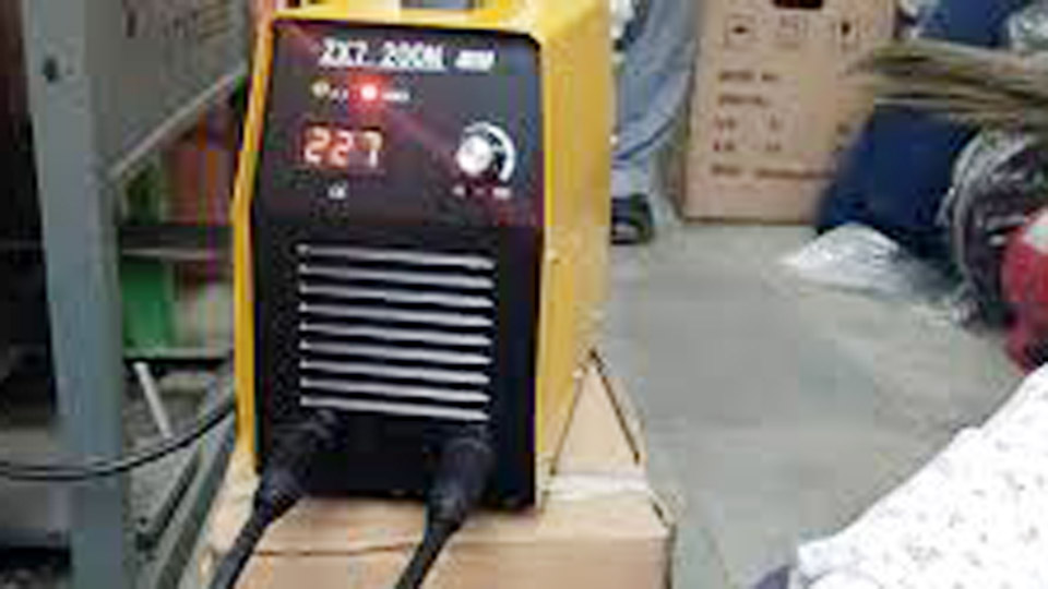
Image by dial4trade
Warning: Disconnect the welder from input power before inspecting plugs, cables, covers, drive systems, or torch parts. Internal capacitors can retain hazardous energy after unplugging. OSHA states that welding-machine repairs should be made only by qualified personnel.
Start With a Safe Troubleshooting Sequence
Work from the outside in. This keeps you from changing several variables at once or opening the machine before you have ruled out the common causes.
- Stop welding and make the area safe. Remove the electrode from the holder, release the gun trigger, close shielding-gas cylinders when appropriate, and disconnect input power before touching equipment.
- Read the display and manual. Record warning lights, error codes, process mode, polarity, amperage, voltage, wire-feed speed, and remote-control settings.
- Check the input supply. Confirm that the receptacle, plug, branch circuit, and input voltage match the welder’s nameplate and manual.
- Inspect external connections. Look for loose lugs, damaged insulation, overheated plugs, worn holders, a dirty work clamp, and coiled or undersized leads.
- Check process-specific items. Verify electrode type and condition, wire size and drive rolls, contact tip, liner, tungsten, shielding gas, and polarity.
- Test on clean scrap. Use material similar to the job and start with the manufacturer’s chart or a qualified welding procedure specification.
- Stop if the problem repeats. Repeated breaker trips, burning smells, visible internal damage, wet equipment, or an error that calls for service should end operator troubleshooting.
Pro Tip: Change one setting or component at a time and write down the result. That simple habit makes intermittent faults much easier to isolate.
Common Symptoms and the First Check
| Symptom | Likely Area | First Safe Check |
|---|---|---|
| No lights, fan, or display | Input supply, disconnect, plug, breaker, or internal fault | Match the receptacle and branch circuit to the nameplate; inspect the plug and reset the correct breaker once |
| Machine powers on but no arc | Work lead, output lead, process mode, remote control, contactor, or consumable | Confirm mode and polarity, then clean and tighten the work connection |
| Breaker trips | Wrong input voltage, overloaded circuit, damaged cord, or internal short | Disconnect other loads and verify the required circuit in the manual; do not install a larger breaker |
| Thermal light or shutdown | Exceeded duty cycle, blocked airflow, failed fan, or hot environment | Leave the unit powered as directed so its fan can cool it, and clear the specified ventilation space |
| Arc stutters or wanders | Low current, poor work connection, arc blow, wrong polarity, or contamination | Clamp to clean metal near the weld and verify the electrode or process setup |
| Wire feeds unevenly | Drive-roll tension, liner, tip, spool brake, or cable routing | Straighten the gun cable and match the roll, liner, and tip to the wire |
| Porosity or dirty bead | Contamination, moisture, wind, gas leak, or poor shielding | Clean the joint and consumables, then verify gas type, flow, and coverage |
Arc Welder Will Not Start or Has No Power
This is one of the first problems that stops a job. You flip the switch and get no fan, light, or display. On a farm-equipment repair, I once traced a dead machine to a tripped breaker on an overloaded job-site circuit. The lesson was simple: verify the input supply before blaming the welder.
Products Worth Considering

Universal Compatibility: 50 ft welder cord fits most 30Amp 3 prong welders on the market; The 10 gauge welding power cord is rated 250Volt, 7500Watts, NEMA 6-50p to NEMA...
Check the Input Supply Without Opening the Case
In the United States, common nominal shop supplies are 120 volts and 240 volts, not the older shorthand of 110 and 220 volts. Many welders can use only one input voltage, while dual-voltage models may require an adapter, an automatic sensing system, or a manual reconnection procedure.
- Read the input voltage, phase, frequency, and rated input current on the nameplate.
- Confirm that the plug and receptacle are not loose, scorched, cracked, or modified.
- Use the branch-circuit size and overcurrent protection specified by the manufacturer and applicable electrical rules.
- Do not replace a fuse or breaker with a larger one simply to stop nuisance trips.
- If an extension cord is permitted, use the gauge and maximum length listed by the welder manufacturer. A single “10-gauge under 50 feet” rule does not fit every machine.
- Have a qualified person test the receptacle and supply voltage when low voltage, an open conductor, or an incorrect phase is suspected.
OSHA requires welding-machine supply conductors and overcurrent protection to be selected for the equipment, and it requires the manufacturer’s operating instructions to be followed. See 29 CFR 1910.254.
Machine Powers Up but Produces No Weld Output
If the display and fan work but the machine will not strike an arc, check the output path before assuming the power electronics have failed.
- Make sure the correct process is selected: stick, MIG, flux-cored, or TIG.
- Check whether the machine is set to panel, remote, or foot-control operation.
- Verify electrode polarity, gun connections, and output-terminal placement.
- Attach the work clamp to clean bare metal on the workpiece or approved fixture, as close to the weld as practical.
- Spread out coiled welding cable and inspect the full length for damaged insulation, overheated connectors, or loose lugs.
- For MIG, check the gun trigger connection, contact tip, and whether wire is actually reaching the tip.
- Record any error code and follow the exact service action in the manual.
Note: The work lead carries welding current back to the power source. It is not a substitute for the equipment-grounding conductor that protects the machine frame.
Blown Fuses or Tripped Breakers
A breaker that opens after welding begins may be reacting to an overloaded or incorrect supply, a voltage mismatch, damaged wiring, or an internal fault. It is not a signal to “size fuses two or three times the motor current.” Welders are not sized by a generic motor rule.
I once pushed a small 140-amp MIG machine beyond its rated duty cycle on thick plate. The correct fix was not a larger fuse or a random 200-amp replacement. It was to use settings and a work pattern within the machine’s rating, or choose equipment with enough output and duty cycle for the job.
- Disconnect other loads from a shared circuit.
- Verify the required input voltage and branch circuit.
- Inspect the power cord and plug for heat damage.
- Reset a breaker only after correcting the likely cause.
- If it trips again, stop using the machine and arrange qualified service.
Overheating and Thermal Shutdown Problems
Overheating shortens component life and can trigger a thermal shutdown in the middle of a weld. The usual causes are exceeding the rated duty cycle, blocked airflow, a failed fan, high ambient temperature, or internal contamination.
Duty cycle is normally stated as a percentage of a 10-minute period at a specific output. A 20% rating at a stated amperage means two minutes of welding and eight minutes of cooling under the rated conditions. The exact cooling procedure and duty-cycle curve come from the machine manual.
Products Worth Considering


Package Contents: you will receive 10 skull caps in different styles, suitable for many kinds of use, sufficient quantity can satisfy your daily use and replacement needs, also nice to share with others
How to Prevent Welder Overheating
- Keep the machine’s air inlets and outlets clear by the distance stated in the manual.
- Remove external dust with the method approved by the manufacturer. Do not blow conductive grinding dust deeper into electronics.
- Keep welding leads uncoiled and connections tight so resistance does not add heat.
- Use the duty-cycle chart for the actual process and output, not a guess based only on the machine’s maximum amperage.
- When thermal protection activates, stop welding and let the machine cool as directed. Many units should remain powered so the internal fan can run.
- Do not bypass the thermostat, thermal relay, fan switch, or warning circuit.
In a hot shop, the available duty cycle may be lower than it is under the test conditions used for the rating. An external fan is not a universal fix because it can upset the designed airflow or pull more dust into the machine. Persistent thermal trips with clear vents and correct use point to a fan, sensor, connection, or internal-service problem.
Arc Instability, Arc Blow, and Poor Starts
An unstable arc can produce spatter, undercut, lack of fusion, and irregular bead shape. Across stick, MIG, and TIG, the first checks are the work connection, polarity, consumable condition, surface cleanliness, and machine settings.
Fixing an Unstable Arc in Stick Welding
In shielded metal arc welding, an arc that pops out or stutters often points to current that is too low, an arc that is too long, a poor work connection, damp or damaged electrodes, or the wrong polarity. Use the electrode manufacturer’s current range as the starting point because rod diameter and classification matter.
- Clean the clamp area to bright metal and make the connection mechanically tight.
- Confirm whether the electrode requires DCEP, DCEN, AC, or more than one permitted option.
- Maintain the arc length recommended for the electrode; low-hydrogen rods generally need a short arc.
- Use hot-start or arc-force controls only as described in the manual. More arc force may reduce sticking but can increase spatter.
- Replace electrodes with cracked, wet, contaminated, or damaged coatings.
Correcting Magnetic Arc Blow
DC welding current can create magnetic fields that push the arc away from the intended path, especially near joint ends, corners, or heavy tack locations. I saw this repeatedly on pipe joints until I changed the work-lead location and welding direction.
- Move the work clamp closer to the weld or to the opposite end of the joint.
- Change the welding direction or use shorter weld segments.
- Reduce arc length and, when the procedure allows, reduce current.
- Wrap or route the work lead to change the magnetic field only when an approved procedure recommends it.
- Use AC if the machine, electrode, material, and welding procedure permit it.
Preventing Electrode Sticking
Sticking is common when amperage is too low, the work connection is poor, the rod is held against the plate too long, or the arc length collapses. Start with the current range printed on the electrode package or data sheet rather than a universal number.
- Clean the start area and clamp location.
- Set the allowed polarity and a current near the middle of the manufacturer’s range.
- Use a controlled scratch or tap start, then lift immediately to the proper arc length.
- Keep the holder and cable connections clean and tight.
- If the machine has hot-start or arc-force control, add only enough to improve starting without creating excess spatter.
While training a beginner, I found that repeated sticking came from dragging the rod without lifting into an arc. Slowing the motion down and practicing starts on scrap improved the bead far more than simply raising the amperage.
MIG Wire-Feed, Spatter, and Gas Problems
MIG machines add a mechanical feed system, contact tip, liner, gun cable, and shielding-gas path. A fault in any one of those parts can make a healthy power source look defective.
No Wire Feed or Erratic Feeding
- Keep the gun cable as straight as practical while testing.
- Match the drive-roll groove, liner, and contact tip to the wire type and diameter.
- Set drive-roll pressure just high enough to feed without slipping. Excess pressure can deform the wire and contribute to birdnesting.
- Check spool-brake tension; too much drag overloads the feed system, while too little can let the spool overrun.
- Inspect the liner for dirt, wrong length, sharp bends, or damage.
- Replace a worn, oversized, undersized, or burned-back contact tip.
- For soft aluminum wire, use the feeding system recommended by the machine and wire manufacturer.
On a trailer repair, erratic feed disappeared after I replaced a kinked liner. That experience is why I now check the entire wire path before adjusting voltage or wire-feed speed.
Reducing Excessive MIG Spatter
Excessive spatter can come from dirty metal, poor work connection, wrong polarity, mismatched voltage and wire-feed speed, excessive stickout, an unsuitable gas, or turbulent gas flow. A fixed table such as “18–22 volts for every 0.030-inch wire job” is too broad because transfer mode, wire type, gas, joint, position, and machine design all change the correct setting.
- Start with the setup chart inside the machine or the manufacturer’s calculator.
- Confirm polarity for solid wire or self-shielded flux-cored wire.
- Clean the nozzle and contact tip without damaging them.
- Adjust voltage and wire-feed speed together until the arc is stable for the selected process.
- Keep the contact-tip-to-work distance within the gun and procedure recommendation.
- Use anti-spatter product sparingly and only where its label allows; keep it out of the liner, drive system, and weld joint unless the product is approved for that use.
Checking MIG Shielding Gas
For carbon-steel short-circuit MIG, a 75% argon/25% carbon-dioxide blend is common, but it is not correct for every wire or transfer mode. Use the gas listed by the wire manufacturer or welding procedure.
- Confirm the cylinder valve is open and the regulator is functioning.
- Set flow while gas is actually moving through the gun.
- Check the hose, fittings, gun O-rings, and diffuser for leaks or restrictions.
- Shield the weld from drafts without blocking safe fume extraction.
- Clean spatter from the nozzle so shielding gas can cover the puddle evenly.
Lincoln Electric’s MIG troubleshooting guide also ties porosity, spatter, and poor penetration to gas coverage, setup, cleanliness, and technique.
TIG Wandering Arc and Contamination
TIG is sensitive to shielding, tungsten condition, polarity, grounding, and airflow. Poor gas coverage may make the arc wander and can leave a gray, sugared, or contaminated weld.
Gas Flow and Leak Checks
For many TIG setups, 15–20 cubic feet per hour is a useful starting range, but cup size, gas lens, tungsten extension, joint shape, and drafts can move the correct flow higher or lower. Miller notes that excessive flow can create turbulence and pull air into the shielding zone.
- Use 100% argon for common steel, stainless, and aluminum TIG work unless the procedure specifies another inert-gas blend.
- Check hoses and fittings with an approved leak-detection solution.
- Keep fans and open doors from blowing across the arc.
- Use enough pre-flow and post-flow to protect the tungsten and hot weld, following the machine manual rather than a fixed 10–15-second minimum.
See Miller’s common TIG welding problems guide for shielding-gas and AC-balance examples.
Tungsten Preparation and AC Balance
- Use the tungsten type and diameter recommended for the current range and machine.
- Grind lengthwise, not around the circumference, using a dedicated clean wheel.
- For DC welding, a tapered point with a small flat is common.
- For modern AC inverter welding, follow the machine maker’s preparation guidance; deliberately balling every tungsten is an outdated universal rule.
- Increase electrode-positive cleaning only as much as needed. Too much EP heats and enlarges the tungsten tip.
- If the tungsten touches the puddle or filler, stop and regrind or replace the contaminated section.
Porosity, Cracks, Undercut, and Incomplete Fusion
Some defects come from technique, but they can also reveal a machine or setup problem. Do not weld over a serious defect and assume the next pass will repair it.
| Defect | Common Causes | Corrective Action |
|---|---|---|
| Porosity | Oil, paint, rust, moisture, wind, gas leak, blocked nozzle, damp flux, or excessive gas turbulence | Remove the defective metal, clean and dry the joint, correct shielding, and use properly stored consumables |
| Cracking | Wrong filler, high restraint, hydrogen, unsuitable preheat/interpass temperature, poor crater fill, or incompatible material | Stop, remove the crack completely, identify the material, and follow an approved procedure for filler and temperature control |
| Undercut | Excess current or voltage, long arc, wrong angle, fast travel, or poor bead placement | Correct the parameter or technique and repair the groove according to the applicable procedure |
| Lack of fusion | Low heat input, fast travel, dirty joint, poor angle, large puddle, or trapped slag | Clean between passes, correct angle and travel, and use enough heat for the joint and position |
| Incomplete penetration | Joint opening or bevel is unsuitable, current is too low, electrode is too large, or travel is too fast | Use the joint design and root opening required by the drawing, code, or welding procedure; then adjust technique and heat input |
| Burn-through | Too much heat, slow travel, excessive gap, or poor backing | Reduce heat input, increase travel speed, use shorter welds, and correct the fit-up or backing method |
Storing Low-Hydrogen Electrodes Correctly
“Dry rods at 250°F” is incomplete advice. For some E7018 products, 250–300°F is an opened-package holding temperature, while reconditioning an electrode that has absorbed moisture may require a different staged cycle. Always use the electrode manufacturer’s data sheet, an approved rod oven, and the job’s welding procedure. Do not use a household food oven.
Joint Preparation and Preheat
A 60-degree bevel, a 1/32-inch root gap, or a 300°F preheat is not universal. Joint angle, root face, root opening, backing, preheat, and interpass limits depend on material grade, thickness, process, position, restraint, code, and welding procedure. This matters most on high-carbon, alloy, cast, pressure-retaining, and structural work.
For load-bearing or code work, use a qualified welding procedure specification and the required inspection method. A good-looking bead alone does not prove full penetration or structural soundness.
Safety Considerations During Troubleshooting
Arc welding exposes the operator to electric shock, ultraviolet and infrared radiation, hot metal, fire, fumes, and compressed-gas hazards. OSHA’s general welding rules are available in 29 CFR 1910.252.
- Electrical safety: Keep gloves and work surfaces dry, replace damaged cable insulation, never wrap electrode cable around your body, and do not use a machine that has become wet until it has been dried and tested.
- Internal repairs: Do not open the case, test capacitors, replace contactors, or bypass interlocks unless you are qualified and using the manufacturer’s service instructions.
- Eye and face protection: Wear a welding helmet and safety glasses with side protection. Select the filter shade by process and current; OSHA’s current table is in 29 CFR 1910.133.
- Clothing: Wear dry flame-resistant clothing, welding gloves, closed footwear, and hearing protection where needed.
- Fumes: Use suitable ventilation or local exhaust, especially on stainless, galvanized, painted, plated, or coated material. Never use oxygen for ventilation.
- Fire prevention: Remove or protect combustibles, check the opposite side of walls or floors, and use a fire watch when the hot-work conditions require one.
- Cylinders: Secure cylinders upright, protect valves, keep them away from the arc and sparks, and inspect hoses and fittings for leaks.
- Confined spaces: Do not treat a tank, vessel, or small enclosure as a normal shop weld. Confined-space welding needs ventilation, gas testing, equipment placement, and rescue controls appropriate to the hazard.
A repeated trip, burning odor, wet machine, damaged insulation, or internal error code is a stop-work signal—not an invitation to install a larger fuse or bypass a safety device.
Machine Maintenance Tips for Longer Service Life
Preventive care catches loose, dirty, and worn parts before they turn into an intermittent arc or a shutdown.
Before Each Use
- Inspect the plug, input cord, electrode holder or gun, work clamp, and welding leads.
- Check that all connectors are fully seated and tight.
- Remove spatter from the work-clamp contact surface, MIG nozzle, and diffuser as needed.
- Confirm the gas hose is sound and the cylinder is secured.
- Verify that air inlets and outlets are clear.
At the Manual’s Service Interval
- Clean the machine by the approved method and inspect cooling fans.
- Inspect drive rolls, guides, liner, contact tip, and spool brake on MIG equipment.
- Check torch parts, O-rings, collets, cups, and water-cooling connections on TIG equipment.
- Tighten only the user-serviceable connections listed in the manual.
- Do not oil sealed fans or motors unless the manufacturer specifically instructs you to do so.
Store the welder and consumables in a dry area away from grinding dust. Inverter machines are compact and efficient, but conductive metal dust can be especially hard on their electronics.
Comparing Stick, MIG, and TIG Problems
| Problem | Stick (SMAW) | MIG (GMAW/FCAW) | TIG (GTAW) |
|---|---|---|---|
| Unstable arc | Check rod, current, arc length, polarity, and work connection | Check voltage/wire-speed balance, feed path, tip, polarity, and work connection | Check tungsten, polarity, work connection, gas coverage, and torch setup |
| Overheating | Follow the process-specific duty-cycle chart, clear airflow, and let thermal protection reset normally | ||
| Porosity | Use dry, undamaged electrodes and clean metal | Correct gas coverage, leaks, wind, nozzle condition, and contamination | Correct gas type and flow, leaks, drafts, tungsten contamination, and post-flow |
| Spatter | Correct current, arc length, polarity, and electrode condition | Balance voltage and wire speed; check gas, stickout, polarity, and cleanliness | Normally limited; investigate contamination, incorrect polarity, or tungsten contact |
| Feeding problem | Not applicable | Check drive pressure, rolls, liner, spool brake, tip, and gun routing | Check filler handling only; the power source does not normally feed wire unless an added feeder is used |
Stick remains useful outdoors and on less-than-perfect surfaces, MIG is productive when the wire and shielding systems are stable, and TIG offers precise control when cleanliness and gas coverage are tightly managed.
Wrapping Up
Most arc welding machine problems become easier to solve when you separate the system into five areas: input power, output connections, machine cooling, process setup, and consumables or shielding. Start with the manual, check the simple external causes, and test one change at a time on clean scrap.
Regular maintenance, correct joint preparation, and settings matched to the electrode, wire, tungsten, material, and procedure prevent many failures before they begin. Just as important, know where operator troubleshooting ends. A repeated breaker trip, wet machine, damaged insulation, burning smell, or suspected internal fault belongs with a qualified repair technician.
Frequently Asked Questions
What causes arc blow in stick welding?
Arc blow is magnetic deflection of the welding arc, most often noticed with DC welding near joint ends, corners, or uneven current paths. Try moving the work clamp, changing direction, shortening the arc, using short segments, or switching to AC when the electrode and procedure allow it.
How do I fix an overheating arc welder?
Stop welding, follow the manual’s cooling procedure, and leave the fan running if the manufacturer directs it. Check the rated duty cycle, blocked vents, hot ambient conditions, coiled leads, and fan operation. If thermal shutdown continues during normal use, arrange qualified service.
Why is my MIG welder not feeding wire properly?
Common causes include excess or insufficient drive-roll pressure, the wrong roll groove, a dirty or kinked liner, too much spool-brake tension, a worn contact tip, burnback, or a sharply bent gun cable. Match every feed component to the wire type and diameter.
What are common causes of porosity in arc welds?
Porosity commonly comes from oil, paint, rust, moisture, damp flux, wind, gas leaks, a blocked nozzle, incorrect gas, or turbulent shielding flow. Remove the porous weld metal, clean and dry the joint, correct the shielding problem, and test on scrap before rewelding the part.
How can I prevent electrode sticking when starting an arc?
Use clean metal, a solid work connection, the correct polarity, and a current within the electrode manufacturer’s range. Scratch or tap the rod, then lift immediately to the recommended arc length. Hot-start or arc-force control can help when used according to the machine manual.
Why does my welder turn on but produce no arc?
Check the selected process, panel or remote-control mode, polarity, output-terminal connections, work clamp, welding leads, holder or gun, and consumable path. Follow any display code. Do not measure or repair internal output circuits unless you are qualified.
Can I keep resetting a breaker that trips while welding?
No. Reset it only after disconnecting the welder and correcting a likely overload or setup problem. If the breaker trips again, stop using the machine. Do not install a larger breaker or fuse unless a qualified person confirms that the circuit, conductors, receptacle, and welder requirements allow it.
Sources
- OSHA 29 CFR 1910.254: Arc Welding and Cutting — equipment hookup, grounding, cable condition, manufacturer instructions, and qualified repairs
- OSHA 29 CFR 1910.252: General Welding Requirements — PPE, fire prevention, ventilation, confined spaces, and coated-metal hazards
- OSHA 29 CFR 1910.133: Eye and Face Protection — minimum filter-shade selection by welding process and current
- Miller Electric: Duty Cycle — 10-minute duty-cycle ratings, thermal protection, and airflow
- Miller Electric: Common TIG Welding Problems — shielding gas, leak checks, polarity, and AC balance
- Lincoln Electric: MIG Problems and Remedies — wire feeding, porosity, spatter, and penetration troubleshooting

[…] MIG or TIG welding, which can be a bit more forgiving on thin gauge steel, arc welding runs hotter and demands steady hands, good joint prep, and the right filler rods. Getting it wrong […]