
One of the most frustrating moments I have had in the shop was laying down a clean bead on sheet metal when my Hobart welder suddenly began feeding wire in fits and starts. The joint was clean and the arc settings looked right, but the wire sputtered, slipped, and then stopped.
A bad feed can create an unstable arc, irregular penetration, excessive spatter, burnback, or a tangled bird-nest at the drive rolls. The good news is that most Hobart welder wire-feed problems can be traced through a logical series of checks before you assume the motor or control board has failed.
Quick Answer
When a Hobart welder will not feed wire, unplug it and check the spool, hub tension, drive-roll groove and pressure, gun-cable position, contact tip, and liner first. If the fan runs but feeding stops after extended welding, let the machine cool normally. Leave motor and circuit-board testing to qualified service personnel.
Affiliate disclosure: This article contains sponsored affiliate links. I may earn a commission from qualifying purchases at no additional cost to you.
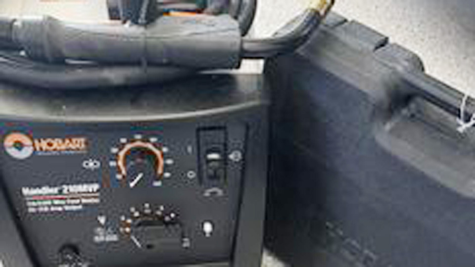
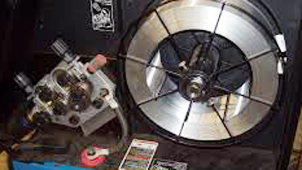
Image by OfferUp.
Key Takeaways
- Start with the entire mechanical feed path before blaming the motor or circuit board.
- Match the drive-roll groove, liner, and contact tip to the exact wire type and diameter.
- Use only enough drive-roll pressure to feed the wire without slipping or flattening it.
- A feed problem and a shielding-gas problem can look similar at the weld, but they require different checks.
- Use the manual that matches the welder’s model and serial number, especially on legacy Handler models.
At a Glance
| Time Required | 10–45 minutes for external checks; longer if the liner or gun parts need replacement |
| Difficulty | Easy to moderate for feed-path maintenance; advanced internal repairs require qualified service |
| Tools Needed | Owner’s manual, eye protection, flashlight, side cutters, pliers, correct contact tip, and clean dry compressed air when appropriate |
| Cost | Often $0 for adjustment; commonly under $50 for basic tips, rolls, or small consumables; gun, motor, board, and shop-service costs vary |
Warning: Unplug the welder before opening the wire compartment, removing the gun, clearing tangled wire, or replacing consumables. Close the shielding-gas cylinder when disconnecting gas equipment. Do not bypass a thermostat, overload protector, or safety interlock, and do not perform energized circuit-board tests unless you are qualified and following the exact service manual.
Why Wire Feed Problems Matter in MIG Welding
A MIG or flux-cored machine depends on a controlled, continuous electrode feed. When wire speed changes unexpectedly, the electrical relationship between voltage, current, arc length, and wire melting also changes. The result may be popping, stubbing, excess spatter, an inconsistent bead, poor tie-in, or burnback at the contact tip.
Wire-feed trouble does not automatically explain every bad weld. Porosity, for example, more often points to inadequate shielding gas, a draft, contamination, damaged gun O-rings, a loose gun connection, incorrect polarity, or a blocked nozzle. Hobart lists porosity and wire feeding as separate troubleshooting categories in its Handler owner’s manual.
That distinction matters. Tightening the drive rolls will not repair a gas leak, and increasing the gas flow will not clear a kinked liner. Diagnose the symptom before changing several adjustments at once.
Common Causes of Hobart Welder Wire Feed Issues
Hobart Handler machines such as the 135, 140, 170, and 175 use a spool, hub, inlet guide, powered drive roll, pressure bearing, gun liner, contact tip, and trigger circuit to deliver wire. Resistance or a fault anywhere along that path can interrupt the feed.
- Spool trouble: Rusty, crossed, kinked, loose, or incorrectly installed wire can bind before it reaches the drive roll.
- Incorrect hub tension: Too much drag makes the motor work harder, while too little drag can let the spool overrun and unravel.
- Wrong drive-roll groove: The roll must match both the wire type and its diameter.
- Incorrect drive pressure: Too little pressure causes slipping; too much can flatten wire, create shavings, and overload the feed system.
- Dirty or damaged inlet guide: Misalignment or debris can scrape the wire before it enters the gun.
- Kinked or blocked liner: Rust, metal flakes, dirt, wear, or a sharply bent cable increases drag.
- Wrong or damaged contact tip: A tip that is undersized, blocked, oval, loose, or covered with spatter can stop the wire.
- Gun connection trouble: A loose gun, trigger plug, thumbscrew, or damaged trigger lead can interrupt motor operation.
- Thermal protection: Welding beyond the rated duty cycle can temporarily stop output until the machine cools.
- Input-power trouble: A loose plug, tripped breaker, low line voltage, or an undersized extension cord can affect operation.
- Internal failure: A failed trigger switch, motor, relay, protector, speed control, or circuit board is possible, but it should be considered after external checks.
Signs Your Hobart Welder Has Wire Feed Problems
| Symptom | Likely Area | First Check |
|---|---|---|
| No fan, no feed, and no weld output | Input power | Plug, receptacle, power switch, breaker, and machine protector |
| Fan runs, but there is no feed or weld output | Thermal or trigger circuit | Thermal indicator, cooling airflow, and trigger connection |
| Gas flows, but the drive roll does not turn | Trigger, motor, or control system | External trigger plug and gun connection; service if secure |
| Drive roll turns, but wire does not move | Mechanical feed path | Roll pressure, correct groove, spool drag, liner, and contact tip |
| Wire surges or changes speed | Intermittent resistance | Straighten the gun cable and inspect the liner, tip, hub, and roll |
| Wire stops after extended welding | Duty cycle or airflow | Stop welding, release the trigger, and let the fan cool the machine |
| Wire tangles beside the drive roll | Downstream blockage | Contact tip, liner, cable bends, and excess drive pressure |
| Wire fuses to the contact tip | Burnback | Tip condition, wire restriction, settings, and electrode stickout |
| Wire feeds steadily, but the weld is porous | Shielding or contamination | Gas supply, leaks, drafts, nozzle, O-rings, polarity, and clean metal |
Step-by-Step Hobart Wire Feed Troubleshooting
1. Identify the Exact Welder
Record the complete model, stock number, and serial number before buying parts or following a wiring diagram. Hobart revised some Handler machines during production, so two welders with the same model name may not use the same gun, control board, drive assembly, or protective component.
Use Hobart’s manual and parts lookup to find the document that matches your machine.
2. Check Input Power
If the fan, feed motor, and weld output are all dead, verify that the plug is fully inserted, the machine is switched on, and the branch-circuit breaker has not opened. Reset only the protector or breaker identified in the owner’s manual.
Avoid a long or undersized extension cord. Excessive voltage drop can reduce weld output and cause poor operation. Use the conductor size and maximum length specified for your exact machine, or connect directly to a suitable receptacle.
3. Inspect the Spool and Hub
Unplug the machine and release the drive-roll pressure. Confirm that the wire spool rotates smoothly and that the wire has not crossed under another wrap. Rust, sharp bends, and loose coils can create intermittent drag.
Adjust the spool-hub tension so the spool stops when feeding stops but still turns without excessive force. The hub should prevent overrun, not act as a brake that strains the feed motor.
4. Verify the Drive Roll
Read the marking on the roll and confirm that the active groove matches the installed wire diameter. On a Handler 140, for example, Hobart provides grooves for common solid and flux-cored wire sizes, but the exact roll can vary with manufacturing date.
Make sure the roll is seated correctly, the groove lines up with the inlet guide and gun liner, and the roll is not polished, packed with debris, or visibly worn.
5. Check the Contact Tip
Remove the nozzle and inspect the tip. Its stamped diameter should match the wire. Replace the tip if wire will not slide through it freely, if the bore has become oval, or if the tip is burned, loose, or packed with spatter.
Do not enlarge a tip with a drill bit. That can create poor electrical contact and an unstable arc.
6. Straighten and Inspect the Gun Cable
Lay the gun cable in a broad, straight path. A tight loop or sharp bend can turn a marginal liner into a serious restriction. Check that the gun is inserted fully into the feed housing and that its retaining thumbscrew and trigger connection are secure.
7. Test the Mechanical Feed Path
With the machine reassembled, point the gun away from people and flammable material. Wear eye protection. Feed wire into a clean wooden block at a slight angle. Increase drive pressure gradually until the wire feeds and curls without the roll slipping, then avoid adding unnecessary pressure.
Pro Tip: Start with low drive pressure and increase it only until slipping stops. Excess pressure can mask a blocked liner while flattening the wire and filling the liner with metal shavings.
8. Check for Thermal Shutdown
If the welder stops only after a period of operation, release the trigger and leave the machine powered so its fan can cool it, as directed by the manual. Do not keep cycling the trigger, block the vents, or bypass the thermal protector.
The Handler 140 model 500559 is rated at 90 amps and 18.5 volts at a 20% duty cycle. That means the rating applies over a ten-minute period at the stated output, not at every possible setting. Higher ambient temperature, blocked airflow, and heavy output can extend the cooling period.
9. Test on Scrap
After correcting the feed problem, install the correct polarity, gas, wire, tip, and drive-roll groove. Use the setup chart inside the welder or the matching owner’s manual as the starting point. Make several test welds on clean scrap of the same type and thickness before returning to the project.
Troubleshooting Hobart Handler 140 Wire Not Feeding
The Hobart Handler family includes several machines, but the Handler 140 is one of the most common 115-volt models. Hobart lists the 500559 version at 25–140 amps, with a rated output of 90 amps at a 20% duty cycle.
For a Handler 140 that will not feed, use this order:
- Verify input power if the fan is also off.
- Check the overtemperature indicator if the fan runs.
- Confirm the gun trigger plug is connected.
- Make sure the gun is fully seated and secured at the feed head.
- Check the spool and hub for excess drag or tangled wire.
- Confirm the active drive-roll groove matches the wire.
- Adjust drive pressure without crushing the wire.
- Straighten the gun cable.
- Replace a blocked or incorrectly sized contact tip.
- Clean or replace a dirty, kinked, or worn liner.
- Have an authorized service technician inspect the drive motor or control system if the external checks pass.
The official Handler 140 product information also lists the supported wire diameters and compatible consumables. Check those details before installing a tip, liner, or roll.
Fixing Wire Feed Problems on Hobart Handler 135
The Handler 135 is a legacy machine, so identify its serial number before ordering a motor, protector, trigger, or control component. Begin with the same external checks used on the 140: plug, trigger connection, spool drag, drive-roll pressure, contact tip, gun cable, and liner.
Some revisions use protective devices in the feed circuit. Never bypass a PTC device, thermostat, or reset protector to “see if it works.” If the motor remains inactive after the gun and mechanical path have been checked, use a Hobart/Miller authorized service agent.
I once started disassembling an older machine because the motor appeared weak. The actual problem was drag from a contaminated liner. That experience is why I now remove the contact tip and check the entire feed path before suspecting an internal component.
Hobart Handler 170 Wire Feed Stopping Intermittently
The Handler 170 is also a legacy model, and its parts should be selected by serial number rather than by model name alone. Intermittent stopping does not prove that its circuit board has failed.
First inspect the gun head, diffuser or tip adapter, contact tip, trigger connection, liner, and drive assembly. Stop using the gun if the head is loose, burned, cracked, or arcing where it should not. Replace damaged consumables with parts approved for the exact gun.
If the feed stops only after a long weld, allow the machine to cool normally and inspect the vents and fan airflow. If the feed stops while the machine is cool and the external path is clear, arrange professional electrical diagnosis rather than applying an outside battery to the motor.
Handler 175 Checks
The Handler 175 follows the same basic troubleshooting pattern: verify the manual and serial number, then check the spool, roll, pressure bearing, gun connection, liner, contact tip, thermal protection, and input supply.
Some Handler 135 and 175 machines used Hobart H-series guns, but gun compatibility can differ. Match the replacement gun or liner to the existing connector and serial-specific parts list.
Step-by-Step Guide to Cleaning Your Wire Liner
A liner that is dirty, kinked, worn, incorrectly sized, or trimmed badly can create surging, bird-nesting, and burnback. Cleaning helps when the liner contains loose dust or wire shavings, but replacement is the better choice when the liner is damaged or remains restricted.
- Unplug the welder. Close the shielding-gas cylinder if you will disconnect the gun or gas equipment.
- Remove the nozzle and contact tip. This opens the wire path and prevents a blocked tip from being mistaken for a liner problem.
- Release drive pressure. Cut the wire near the drive assembly and pull it out from the gun end so dirty wire is not dragged backward through the liner.
- Remove the gun as the manual directs. Do not force the connector or damage trigger leads.
- Use clean, dry compressed air. Wear eye protection and direct debris away from yourself and other people.
- Inspect the liner. Replace it if kinked, crushed, rusty, incorrectly sized, badly worn, or still blocked.
- Trim a replacement precisely. Follow the gun manufacturer’s instructions because a liner that is too short or too long can cause feed trouble.
- Reassemble the gun. Install a tip that matches the wire diameter and secure the gun fully in the feed housing.
- Reload and test. Set light drive pressure, perform the wooden-block test, and make a test weld on scrap.
Note: Inspect the liner and wire condition when changing spools, but do not treat replacement or cleaning as a fixed monthly requirement. Service it when inspection, feed resistance, contamination, or the manufacturer’s maintenance schedule indicates a need.
Adjusting Wire Feed Tension on Hobart Welders
There are two separate adjustments to consider: spool-hub tension and drive-roll pressure. They perform different jobs.
Spool-Hub Tension
The hub should let the spool turn freely while preventing it from coasting after the motor stops. If it is too tight, the motor must pull against excessive drag. If it is too loose, wire can spill from the spool and cross under another coil.
Drive-Roll Pressure
Release the pressure arm, guide the wire through the correct groove, and close the arm. Begin with light pressure. While feeding against a wooden block, increase pressure gradually until the wire curls without slipping. Miller’s manufacturer guidance recommends increasing pressure only slightly beyond the point where slipping stops.
Examine the wire after the test. It should not be visibly flattened, deeply scored, or covered in shavings. Those signs mean the pressure is excessive, the roll type is wrong, or there is a restriction farther down the gun.
Choosing the Right Drive Rolls for Your Hobart
The roll must match the wire’s hardness, construction, and diameter. Hobart’s exact roll names and part numbers vary by machine, so confirm them in the manual or parts list.
| Wire Type | Typical Roll Style | Setup Notes | Main Benefit | Common Mistake |
|---|---|---|---|---|
| Solid steel or stainless | Smooth V-groove | Use the groove stamped for the exact wire diameter | Smooth support for firm wire | Using a knurled roll that creates shavings |
| Self-shielded flux-cored wire | VK or knurled groove specified by Hobart | Use only enough pressure for reliable grip | Grips softer tubular wire | Overtightening and crushing the wire |
| Aluminum | U-groove when specified | May also require the proper liner, short straight cable, spool gun, or push-pull system | Supports soft wire without severe deformation | Assuming a U-groove makes every standard gun aluminum-ready |
For the Handler 140, Hobart has supplied Quick Select rolls with grooves for common .024-inch and .030/.035-inch solid wire and .030/.035-inch flux-cored wire. Check the roll markings because the included configuration can vary by production date.
You can also review manufacturer guidance on drive-roll selection, pressure, and liner maintenance.
Products Worth Considering

Package Contents: You will get 2* Drive Roll, 0.6-0.8mm, 0.8-1.0mm. Installation: High precision and high strength,Quick and easy to install. Usage Method: These rollers are...
Dealing with Bird-Nesting in Hobart MIG Welders
Bird-nesting occurs when wire continues to move at the drive assembly but cannot travel freely through the gun. It folds and tangles between the drive roll and liner entrance.
Common causes include:
- A blocked or undersized contact tip.
- A kinked, dirty, worn, or incorrectly sized liner.
- A sharply bent gun cable.
- An improperly trimmed liner.
- Excessive drive-roll pressure.
- A misaligned inlet guide or gun liner.
- The wrong roll type or groove size.
- Soft aluminum wire being pushed through an unsuitable setup.
To clear a bird-nest, release the trigger and unplug the welder. Release drive pressure, cut away the tangled wire, remove the contact tip, and pull the remaining wire out through the gun end. Do not simply tighten the pressure and try to push the tangle through.
Inspect the entire path before reloading. A bird-nest is usually the result of downstream resistance, not a sign that the rolls need maximum pressure.
Preventing Burnback in Your Welds
Burnback occurs when the energized wire melts back and fuses inside the contact tip. It may follow a sudden feed restriction, a worn tip, unsuitable settings, or holding the tip too close to the work.
Use this checklist:
- Install a clean tip that matches the wire diameter.
- Confirm the liner and drive system feed smoothly.
- Use the voltage and wire-speed starting point printed for the exact wire, gas, and material thickness.
- Maintain suitable electrode stickout. Hobart gives approximately 3/8 inch for solid wire and 1/2 inch for flux-cored wire in the cited Handler manual.
- Keep the gun cable as straight as practical.
- Replace a loose or damaged tip adapter or diffuser.
Do not respond to every burnback by increasing wire speed. A blocked tip or liner may remain hidden, and excessive wire speed can make the electrode stub into the work.
Anti-spatter compound can help reduce buildup on the nozzle when used according to its label, but keep it away from the drive rolls, liner interior, and electrical contact surfaces.
When to Replace the Circuit Board or Motor
Consider internal failure only after you have verified the power supply, trigger connection, gun seating, spool movement, drive-roll setup, contact tip, liner, thermal status, and mechanical feed path.
Professional diagnosis is appropriate when:
- The external trigger and gun connections are secure but the motor never runs.
- The motor or control area produces an abnormal smell, smoke, visible arcing, or repeated protective shutdowns.
- Wire speed changes without a mechanical restriction or control adjustment.
- A protector opens repeatedly under normal load.
- The exact service procedure requires energized voltage measurements.
- Internal wiring, a relay, motor, speed control, or printed circuit board appears damaged.
Do not short trigger terminals or connect an outside battery to an installed motor unless the exact factory service procedure calls for it and you are qualified to perform the test. Incorrect polarity or an accidental short can damage an otherwise repairable assembly.
Board and motor prices vary widely by part number, serial number, availability, and labor. On an older machine, compare a written repair estimate with the cost and capability of a replacement welder. Rebuilt electronics should come from a qualified service provider that identifies the exact board number and repair warranty.
Safety Considerations for Wire Feed Repairs
Welding equipment combines household or industrial input power, stored electrical energy, moving drive parts, sharp wire, compressed gas, hot metal, ultraviolet radiation, sparks, and fumes. OSHA identifies burns, eye damage, electrical shock, cuts, radiation, and fume exposure among the hazards of welding and cutting.
- Unplug the machine before feed-path service.
- Do not remove internal covers simply because the power cord is disconnected; capacitors may retain energy.
- Keep hands away from powered drive rolls and never defeat a guard.
- Wear safety glasses when cutting wire or using compressed air.
- Use a welding helmet, flame-resistant clothing, gloves, and suitable footwear when striking an arc.
- Provide effective ventilation or local fume extraction appropriate to the material and process.
- Remove or protect nearby combustibles and keep suitable fire-control equipment available.
- Do not weld on closed containers or unknown coated metal.
- Never override the thermostat or overload protection.
- Stop using equipment with damaged insulation, plugs, gun cables, or exposed conductors.
For workplace requirements and broader hazard controls, review OSHA’s welding, cutting, and brazing safety guidance.
Real-World Applications and Tips for Hobart Users
Consistent feeding matters on farm repairs, automotive sheet metal, home fabrication, and heavier flux-cored work. The correct setup, however, depends on more than wire diameter.
Record the following when a setup works well:
- Welder model and voltage position.
- Wire type, classification, and diameter.
- Wire-speed control position.
- Shielding gas and flow setting.
- Material type and thickness.
- Joint design and welding position.
- Polarity.
- Gun angle, travel speed, and stickout.
Do not use 18–20 volts and 200–300 inches per minute as a universal setting for .030-inch wire. A Handler 140 uses voltage positions, and the correct combination changes with the material, gas, wire, joint, and position. Start with the chart inside the door or the matching manual and fine-tune on scrap.
ER70S-6 is a common solid-steel MIG wire, but it is not automatically correct for every base metal, shielding gas, procedure, or code requirement. Use filler metal approved for the job. Structural and safety-critical repairs may require a written welding procedure and a qualified welder.
For automotive work, follow the vehicle manufacturer’s repair information. Protect electronics, place the work clamp close to the weld where instructed, and do not weld on fuel, restraint, high-voltage, or pressurized systems without the required isolation procedures.
Most wire-feed failures are found by tracing resistance from the spool to the contact tip—not by turning the pressure knob tighter.
Comparison of Hobart Models for Wire Feed Reliability
Hobart Handler machines are generally designed around similar feed-path principles, but their electrical systems, rated outputs, guns, and replacement components are not interchangeable. A model name alone is not enough for ordering internal parts.
| Model | Status or Verified Detail | What to Check First | Parts Guidance |
|---|---|---|---|
| Handler 135 | Legacy model | Spool, hub, roll, tip, liner, trigger connection, and thermal protection | Use the serial-specific manual; do not assume Handler 140 electronics are identical |
| Handler 140 model 500559 | 115 V; 25–140 A; rated 90 A at 20% duty cycle | Input power, temperature indicator, gun connection, Quick Select roll, tip, and liner | Verify current compatible consumables on Hobart’s product and parts pages |
| Handler 170 | Legacy model; specifications vary by exact unit | Gun head, trigger, spool drag, feed path, thermal status, and input supply | Confirm nameplate, stock number, and serial number before ordering |
| Handler 175 | Legacy model | Gun seating, roll pressure, contact tip, liner, hub tension, and thermal protection | Match gun and internal components to the serial-specific parts list |
The best model is the one that matches your input power, material range, duty-cycle needs, and process. Feed reliability still depends heavily on clean wire, correct consumables, proper adjustment, and routine inspection.
Products Worth Considering

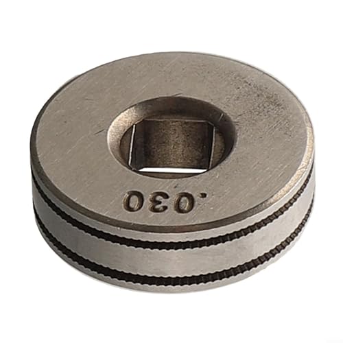
【Precision Design】The Mig Welder Wire Feed Drive Roller Roll Wheel is specifically designed for electric kits, ensuring precise and efficient wire feeding.

Scope Of Application: Welding auxiliary machine is suitable for 0.8/1.0mm welding wire, suitable for welding in industry, woodworking and equipment, with fast and smooth wire feeding
Conclusion
Hobart welder wire-feed problems are easiest to solve when you work from the spool toward the contact tip. Check spool drag, drive-roll type and pressure, guide alignment, gun seating, cable bends, liner condition, and tip size before assuming an electrical failure.
If feeding stops after the machine has been working hard, respect the duty cycle and allow its normal cooling system to operate. If every external check passes and the motor or control circuit remains inactive, stop there and arrange qualified service rather than bypassing a protector or applying improvised power.
A careful feed-path inspection usually costs less and takes less time than replacing parts at random. Once the wire feeds smoothly, return to the manufacturer’s setup chart, test on matching scrap, and confirm a stable weld before continuing the job.
Frequently Asked Questions
Why does my Hobart welder stop feeding wire mid-weld?
If it stops only after extended welding, the thermal protector may have opened because the rated duty cycle was exceeded. Release the trigger and let the fan cool the machine normally. If it stops while cool, inspect the spool, drive-roll pressure, contact tip, liner, gun connection, and input supply.
How do I fix bird-nesting in my Hobart MIG welder?
Unplug the welder, release roll pressure, cut away the tangled wire, remove the contact tip, and pull the remaining wire out through the gun end. Inspect the tip, liner, cable bends, guide alignment, roll groove, and pressure before reloading.
What is the best wire feed speed for mild steel on a Hobart 140?
There is no single best speed. Use the chart inside the machine or the matching owner’s manual for the wire diameter, gas, polarity, and steel thickness. Test the suggested voltage position and wire-speed setting on matching scrap, then adjust for a stable arc and proper bead shape.
Can I repair a faulty circuit board on my Hobart welder?
A qualified electronics or welding-equipment technician may be able to repair it, but first confirm the exact board number and welder serial number. Internal diagnosis can involve hazardous voltage and stored energy, so it is not a suitable general DIY procedure.
How often should I clean the liner in my Hobart welder?
Inspect the liner and wire whenever you change spools or notice increased feed resistance. Blow out loose debris with clean, dry air when the gun manufacturer permits it. Replace the liner if it is kinked, worn, incorrectly sized, rusty, or still restricted after cleaning.
Why do the drive rolls turn while the wire stays still?
The roll may be using the wrong groove, pressure may be too low, the spool hub may be too tight, or the wire may be blocked in the tip or liner. Release pressure and determine where the wire stops moving instead of immediately tightening the roll.
Can I feed aluminum through the standard Hobart MIG gun?
Only when the specific machine and gun support that setup. Aluminum is soft and may require a U-groove roll, compatible liner, minimal cable bends, and carefully set pressure. A compatible spool gun or push-pull system is usually more reliable.
Sources
- Hobart Handler Owner’s Manual — troubleshooting, thermal protection, drive rolls, liner checks, stickout, and setup guidance
- Hobart Handler 140 Product Information — rated output, input voltage, wire sizes, and compatible consumables
- Hobart Manuals and Parts — serial-specific manuals and replacement-parts lookup
- Miller Wire-Feeding Troubleshooting Guidance — drive-roll selection, pressure adjustment, and liner maintenance
- Miller MIG Weld Defects and Aluminum Feeding Guide — bird-nesting, burnback, U-groove rolls, liners, and spool-gun options
- OSHA Welding, Cutting, and Brazing Hazards — electrical, fume, radiation, burn, eye, and fire safety

I’ve seen references to a liner cleaning tool in several of these how-to posts. So far, no one ID’s the part # for the cleaning tool. Is there such a beast? Also, I’ve seen several references to, pulling a solvent-soaked rag pulled through the liner. First, no one ID’s the best solvent for the task. Second, I defy anyone to pull a solvent-soaked rag through the liner. Please help.