When I first tried to MIG weld 304 stainless steel, discoloration, porosity, and uneven fusion made the job harder than it looked. Stainless responds quickly to excess heat, poor shielding, and carbon-steel contamination, so your wire, gas, joint preparation, and gun technique all need to work together.
Quick Answer
To MIG weld 304 stainless steel, clean and fit the joint carefully, use ER308L or ER308LSi wire, set the machine to DCEP, and choose a low-CO₂ stainless shielding gas that matches your transfer mode. Use a controlled push technique, short stringer beads, steady travel, and enough cooling time to limit distortion and oxidation.
With the right setup, MIG can produce strong and corrosion-resistant welds on 304 and 304L without the slower pace of TIG. The process works especially well for fabrication, repairs, and production work where speed matters, but you still need a test coupon before welding the finished part.
Key Takeaways
- Use ER308L or ER308LSi for 304 and 304L. Use ER309L or ER309LSi when joining 304 stainless to carbon or low-alloy steel.
- Match the shielding gas to the transfer mode. Helium-rich tri-mix is common for conventional short circuit, while argon-rich low-CO₂ or low-O₂ blends suit spray and pulsed spray.
- Keep stainless separate from carbon-steel brushes, abrasives, work tables, and dirty wire-feed parts.
- Use straight stringer beads, controlled travel speed, frequent tacks, and a balanced weld sequence to limit heat tint and distortion.
- Control welding fumes with local extraction. Stainless welding can produce hazardous hexavalent chromium.
At a Glance
| Time Required | About 30–90 minutes for setup, test coupons, and a small joint. Larger assemblies take longer. |
| Difficulty | Intermediate. Basic MIG experience is strongly recommended. |
| Tools Needed | MIG welder, stainless wire, correct shielding gas, regulator or flowmeter, dedicated liner and feed parts, clamps, stainless brush, clean abrasives, PPE, and fume extraction. |
| Cost | Low if you already own a suitable welder. Stainless wire, shielding gas, dedicated consumables, and post-weld treatment are the main added costs. |

What Makes 304 Stainless Steel Different
Type 304 is an austenitic stainless steel commonly described as an 18% chromium and 8% nickel alloy. Chromium helps form the passive surface layer that gives stainless steel its corrosion resistance. Nickel helps stabilize the austenitic structure and supports formability and toughness.
Type 304 permits more carbon than 304L. The lower carbon content of 304L reduces the risk of chromium-carbide precipitation during welding and improves resistance to intergranular corrosion. That does not make heat control optional. Excess heat can still cause distortion, heavy oxide scale, root oxidation, and loss of corrosion performance. You can review current 304 and 304L grade information from Outokumpu.
Austenitic stainless can become sensitized after enough time in a temperature range of roughly 425–870°C, or 800–1600°F. Welding cycles pass through that range quickly, so low-carbon base metal and filler help, but repeated passes, slow travel, and high interpass temperatures still deserve careful control.
Annealed 304 is usually non-magnetic or only weakly magnetic. Cold forming, machining, and welding can increase its magnetic response, so do not assume every finished 304 assembly will meet a strict low-permeability requirement.
304 works well in many indoor, atmospheric, food-processing, and mildly corrosive applications. For sustained saltwater, deicing salt, or other strong chloride exposure, confirm that 304 is suitable. A more corrosion-resistant grade such as 316L may be required.
When MIG Is a Good Choice for 304 Stainless
MIG welding is fast, productive, and easier to automate than TIG. It works well on sheet, plate, frames, tanks, carts, brackets, and production assemblies when the joint design and machine output suit the material.
Short-circuit transfer can handle thinner material and out-of-position work. Conventional spray transfer provides high deposition and smooth transfer on thicker material, but its fluid puddle normally limits it to flat and horizontal positions. Pulsed spray uses a controlled peak-and-background current cycle, which improves puddle control and allows many out-of-position applications while reducing average heat input.
TIG is often the better option for very thin sheet, delicate edges, cosmetic joints, controlled tube roots, or jobs where precise heat and filler control matter more than speed.
Confirm the Job Requirements Before You Weld
Before loading wire, identify the exact base material, thickness, joint type, welding position, and service environment. A part marked only as “stainless” may not be 304, and filler selection changes when you join different grades.
- Confirm the grade: Verify whether the material is 304, 304L, another 300-series grade, or an unknown alloy.
- Check the service: Consider chloride exposure, temperature, chemicals, hygiene, pressure, fatigue, and appearance requirements.
- Identify the joint: Butt, lap, fillet, tube, and dissimilar-metal joints need different fit-up and penetration.
- Choose the transfer mode: Base the choice on thickness, position, machine capability, and shielding gas.
- Check governing requirements: Structural, pressure, sanitary, marine, automotive-safety, and customer-controlled work may require a qualified welding procedure specification, approved filler, welder qualification, inspection, and documented parameters.
Note: This guide provides general workshop guidance. It does not replace a qualified WPS, engineering drawing, code requirement, material specification, or workplace exposure assessment.
Essential Equipment and Consumables
Products Worth Considering

ER308L WIRE: A low-carbon stainless steel wire engineered to minimize intergranular carbide precipitation. This enhances corrosion resistance without the need for stabilizers, making it ideal for critical applications.

This solid wire REQUIRES a shielding gas

Enhanced Arc Stability: With an internal flux core, ARCCAPTAIN E308LFC-O Flux Cored Stainless Steel Welding Wire stabilizes the arc, enhancing operational performance and providing a protective barrier.
MIG Welder and Gun
Use a constant-voltage MIG welder with enough output and duty cycle for the joint thickness. A pulse-capable machine helps when you need spray-type transfer with lower average heat or better out-of-position control.
Fit a contact tip that matches the wire diameter. Check the gas diffuser, nozzle, gun cable, return lead, and connections before welding. Loose electrical connections or a worn contact tip can destabilize the arc.
Dedicated Stainless Wire-Feed Parts
Use a clean liner, contact tip, inlet guide, and feed path. Dedicated parts reduce the chance of carrying carbon-steel dust into the weld.
Drive-roll selection needs manufacturer guidance. V-groove rolls are commonly used for solid wire. However, some manufacturers recommend V-knurled rolls for hard stainless wire when V-groove rolls cannot grip it consistently. If you use knurled rolls, apply only enough tension to feed the wire and inspect the liner for metallic shavings. Hobart’s general drive-roll guidance explains the tradeoffs.
Cleaning, Fitting, and Purging Tools
- Stainless-only wire brush
- Clean abrasives reserved for stainless
- Non-chlorinated degreaser
- Clamps and distortion-control fixtures
- Clean return clamp
- Regulator or flowmeter rated for the shielding gas
- Leak-detection solution approved for gas equipment
- Purge dams, foil, tape, hoses, and an oxygen monitor when the root must be purged
- Copper backing or chill bars where the joint permits them
Personal Protective Equipment
- Welding helmet with a suitable shade
- Safety glasses with side protection
- Leather welding gloves and flame-resistant clothing
- Hearing protection for grinding and noisy fabrication
- Local fume extraction positioned close enough to capture the plume without pulling shielding gas away from the arc
- Respiratory protection when required by an exposure assessment and respiratory-protection program
Choose the Right Filler Wire
For 304 or 304L joined to the same family of stainless steel, use ER308L or ER308LSi. The added silicon in ER308LSi improves puddle fluidity and wetting, which can produce a smoother bead profile.
When joining 304 stainless to carbon or low-alloy steel, ER309L or ER309LSi is the usual starting choice because it better tolerates dilution from the dissimilar base metals. Hobart’s austenitic stainless filler guide supports 308/308L for 304L and 309 for stainless-to-carbon-steel joints.
Do not use ordinary ER70S mild-steel wire when corrosion resistance matters. The deposited metal will not match the stainless base material, and the joint may rust or fail to meet service requirements.
Common solid-wire diameters include:
- 0.023 or 0.024 inch: Helpful for very thin sheet when the machine and wire are available.
- 0.030 inch: A practical choice for thin sheet and lighter fabrication.
- 0.035 inch: A common general-purpose size for medium sheet and plate.
- 0.045 inch: Better suited to higher-output equipment, thicker work, and higher deposition rates.
The usable range depends on the machine, joint, transfer mode, and wire manufacturer. Do not select wire diameter from thickness alone.
Products Worth Considering
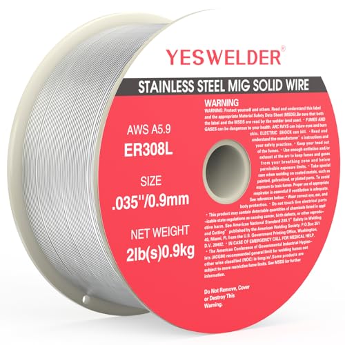
ER308L WIRE: A low-carbon stainless steel wire engineered to minimize intergranular carbide precipitation. This enhances corrosion resistance without the need for stabilizers, making it ideal for critical applications.

Premium Low Carbon Mig Wire: Achieve high-grade welding results with our ER308L stainless steel MIG wire. Featuring a low carbon content, it minimizes intergranular carbide precipitation, enhancing corrosion resistance without the need for stabilizers.

1 Pound spool and .030 inch diameter
Match the Shielding Gas to the Transfer Mode
Stainless solid-wire GMAW normally uses argon-based gas with a small active component. The active gas stabilizes the arc and improves wetting, but excessive CO₂ can increase oxidation and affect corrosion performance.
| Gas or Gas Family | Typical Use | Advantages | Limits |
|---|---|---|---|
| About 90% He / 7.5% Ar / 2.5% CO2 | Conventional short-circuit transfer | Fluid puddle, useful penetration, good low-current performance | Higher cost and uneven regional availability |
| About 98% Ar / 2% CO2 | Pulsed spray and many general stainless programs | Stable arc, low active-gas content, widely available in some markets | Confirm compatibility with the wire and machine program |
| About 98% Ar / 2% O2 | Spray or pulsed spray where specified | Good wetting and arc stability | Not normally the first choice for low-current short circuit |
| Approximately 95–98% Ar / 2–5% CO2 | Pulsed or spray programs approved for the blend | Stable transfer and practical availability | Higher CO2 can increase oxidation; keep it within the wire and procedure limit |
| 100% argon | Not recommended as the general solid-wire stainless GMAW gas | Useful for TIG, root purging, and MIG welding some non-ferrous metals | Can produce poor wetting, an unstable arc, and incomplete fusion in stainless GMAW |
| 75% Ar / 25% CO2 C25 | Not the normal choice for solid-wire 304 stainless | Common and economical for carbon steel | CO2 content is much higher than normal stainless solid-wire recommendations |
Miller recommends keeping CO₂ below 5% for stainless and describes helium-rich blends for conventional MIG and argon-rich blends for pulsed MIG. Linde similarly describes stainless GMAW blends with small active additions, normally in the low single-digit range. Review the current guidance from Miller and Linde.
Prepare the 304 Stainless Joint
- Confirm the material. Remove protective film only where needed and verify that the part is actually 304 or 304L.
- Remove oil and marking residue. Use a suitable non-chlorinated cleaner. Let flammable solvent evaporate completely before welding.
- Remove oxide and contamination. Use stainless-only brushes and clean abrasives. Do not use a wheel that has touched carbon steel.
- Prepare the joint. Use the groove angle, root face, root opening, and bevel required by the joint design or WPS. A square edge may work on thin material, while thicker full-penetration joints may need a bevel.
- Fit the parts tightly. Uneven gaps make thin stainless harder to weld without burn-through.
- Clamp and fixture the assembly. Stainless expands and contracts enough to pull long joints out of alignment.
- Place frequent tacks. Keep the tacks small, evenly spaced, and fully fused. Remove defective or contaminated tacks.
- Attach the return clamp. Place it on clean metal with a short, direct electrical path.
Warning: Never weld near chlorinated solvents or residue from chlorinated cleaners. Arc heat and ultraviolet radiation can create extremely hazardous decomposition products. Keep all solvent containers away from sparks and confirm that cleaned surfaces are dry before welding.
Set Up the MIG Welder
Set the machine to DCEP, also called electrode positive, unless the wire manufacturer specifies otherwise. Install the correct wire program, contact tip, drive-roll size, and shielding gas.
| Variable | Starting Point | What to Watch |
|---|---|---|
| Polarity | DCEP | Confirm the wire label and machine manual |
| Gas flow | About 20–30 CFH indoors | Nozzle size, drafts, leaks, and excessive turbulence |
| Short-circuit stickout | About 3/8 inch | Excessive stickout reduces arc heat and gas coverage |
| Pulsed or spray stickout | About 5/8–3/4 inch when specified by the program | Keep it steady because pulse programs respond to CTWD changes |
| Travel angle | Push approximately 10–15 degrees | Avoid an extreme angle that weakens shielding |
| Bead movement | Straight stringer bead | Avoid unnecessary weaving and dwell time |
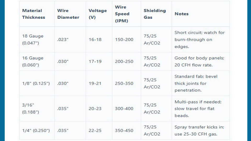
Use the voltage and wire-feed values printed on your machine chart as the first reference. Then compare them with the wire manufacturer’s data. For example, ESAB’s 0.035-inch ER308LSi data lists a broad 15–28 V and 138–709 IPM operating range across different transfer modes and applications.
For a 1/8-inch test coupon using 0.035-inch ER308L or ER308LSi in short-circuit transfer, approximately 18–20 V and 200–250 IPM may be a reasonable trial only when your machine chart recommends a similar area. Do not copy those numbers blindly. Tune the arc on scrap of the same grade, thickness, joint, and position.
Pro Tip: Change one control at a time on your test coupon. Wire-feed speed mainly changes current and deposition, while voltage changes arc length and bead shape. Record the final voltage, wire speed, gas flow, stickout, and travel method once the coupon shows sound fusion.
Step-by-Step: MIG Weld 304 Stainless Steel
-
Position and clamp the joint.
Support the work so you can keep a steady gun angle. Use fixtures, backing, or chill bars where the joint allows them.
-
Check gas coverage.
Open the cylinder, set the flow while gas is moving, and test the fittings for leaks. Clean spatter from the nozzle and confirm that the diffuser is not blocked.
-
Make and inspect the tacks.
Place small tacks at regular intervals. Check that each tack has fused into both sides of the joint before welding over it.
-
Set your gun position.
Use the correct work angle for the joint and a push travel angle of about 10–15 degrees. Maintain the stickout recommended for your transfer mode.
-
Start on a run-on area when possible.
Establish the arc before the finished section so the start does not leave a cold spot or oversized lump.
-
Travel steadily with a stringer bead.
Watch the leading edge of the puddle and both joint toes. Move fast enough to prevent an oversized heat-affected zone, but not so fast that the bead stops tying into the joint.
-
Fill the crater.
Use the machine’s crater-fill control when available. Otherwise, briefly pause or backfill without creating a large hot spot. Keep the nozzle near the crater during post-flow.
-
Allow controlled cooling.
Do not quench the weld unless an approved procedure specifically requires it. Move to another section or allow the joint to cool before adding more heat.
-
Inspect the weld.
Look for consistent width, smooth tie-in, complete fusion, acceptable reinforcement, and no visible porosity, cracking, undercut, or burn-through.
Control Heat and Distortion
Stainless steel expands more during heating and conducts heat less efficiently than carbon steel. Heat stays concentrated near the weld, which makes thin parts prone to warping.
- Use frequent, evenly spaced tacks.
- Keep the joint gap consistent.
- Use stringer beads instead of broad weaves.
- Increase travel speed when the bead remains fully fused.
- Use skip-welding or backstep sequences on long seams.
- Alternate between separated sections instead of completing one long hot run.
- Balance welds on opposite sides when the design permits it.
- Use copper chill bars or backing where they will not contaminate or obstruct the joint.
- Follow the WPS interpass-temperature limit on multi-pass work.
- Use pulsed MIG when the equipment, gas, and wire program support it.
Pulsed MIG switches between peak and background current. This keeps the arc established while allowing the puddle to cool slightly between transfer events. It can reduce spatter, burn-through, and distortion while improving out-of-position control. Miller provides a detailed overview in its pulsed MIG guide.
When and How to Back Purge
Back purging protects the root side of a full-penetration stainless joint from air. Without protection, the hot root can develop heavy granular oxidation often called sugaring. That oxide can reduce corrosion resistance, trap contamination, and create an unacceptable sanitary surface.
You may need a purge for:
- Full-penetration tube and pipe welds
- Food, beverage, pharmaceutical, or hygienic service
- Corrosive process piping
- Joints whose inside surface cannot be cleaned after welding
- Work governed by a WPS or customer oxygen limit
A fillet weld, lap joint, or partial-penetration joint does not automatically need a purge. Base the decision on root exposure, joint design, service, and the governing procedure.
- Seal the root area with suitable purge dams, foil, or heat-resistant tape.
- Place the argon inlet low when practical because argon is denser than air.
- Provide a separate outlet so displaced air and excess gas can escape.
- Use enough flow to replace the air without pressurizing the joint or disturbing the molten root.
- Measure oxygen when the specification sets an acceptance limit.
- Maintain the purge until the root has cooled enough to resist rapid oxidation.
Note: Do not seal both ends of a purge chamber without a vent. Trapped gas can expand as the joint heats. Purging can also displace breathable oxygen in an enclosed work area, so provide proper ventilation.
Post-Weld Cleaning and Corrosion Protection
Heat tint is an oxide layer produced during welding. Darker tint usually indicates more oxidation, but color alone cannot prove whether a weld meets a corrosion requirement.
Start with the least aggressive treatment that meets the service requirement:
- Stainless or nylon brushing: Removes light surface residue and some superficial tint.
- Clean abrasive finishing: Blends the weld and removes heavier oxide when permitted by the finish specification.
- Electrochemical cleaning: Can remove tint and assist passivation when performed with the correct equipment and chemical.
- Pickling: Removes oxide and the chromium-depleted layer beneath it, but commonly uses highly hazardous acids and requires trained handling, PPE, ventilation, neutralization, and lawful disposal.
- Passivation: Removes free iron and supports formation of a clean passive surface. It does not replace proper removal of heavy weld oxide.
Mechanical brushing may improve appearance without fully removing the chromium-depleted layer. For demanding corrosion or sanitary service, follow the project’s specified cleaning and passivation process. Outokumpu explains these limitations in its post-fabrication treatment guide.
Troubleshooting 304 Stainless MIG Welds
| Symptom | Likely Causes | Corrections |
|---|---|---|
| Porosity | Oil, moisture, drafts, gas leak, blocked diffuser, dirty nozzle, excessive stickout, or turbulent gas flow | Clean and dry the joint, repair leaks, shield drafts, clean the nozzle, shorten stickout, and reset flow while gas is moving |
| Tall rope-like bead | Low voltage, excessive wire feed for the voltage, fast travel, poor wetting, or unsuitable gas | Increase voltage slightly, balance wire speed, slow only enough for tie-in, verify the gas, or adjust inductance if available |
| Undercut | Excessive voltage, excessive travel speed, wrong angle, or failure to fill the toes | Reduce voltage or speed, correct the work angle, and maintain controlled toe fusion |
| Cold lap or lack of fusion | Low heat, excessive stickout, poor joint access, wrong gas, or travel that is too fast | Increase output within the procedure, shorten stickout, improve joint preparation, verify gas, and watch both toes |
| Burn-through | Excessive heat, wide gap, slow travel, or poor fit-up | Reduce heat, increase travel speed, tighten the gap, use pulse or shorter weld segments, and add backing where suitable |
| Heavy heat tint or black surface | High heat input, slow travel, weak shielding, excessive stickout, contamination, or unsuitable gas | Increase controlled travel speed, improve gas coverage, clean the joint, correct stickout, and verify the blend |
| Wire slipping or birdnesting | Wrong roll type or size, poor tension, clogged liner, sharp gun bend, worn tip, or damaged wire | Match the rolls to the wire, reset tension, replace dirty parts, straighten the gun cable, and inspect the spool |
| Crater crack | Abrupt arc stop, unfilled crater, excessive restraint, or unsuitable filler | Use crater fill or backfill, reduce restraint where possible, and verify the filler and procedure |
| Warping | Long continuous beads, poor sequencing, weak fixturing, or excessive heat | Use more tacks, skip sequences, balanced welds, shorter beads, cooling time, and stronger fixtures |
Safety When MIG Welding Stainless Steel
Welding stainless steel can generate hexavalent chromium, or Cr(VI). Cr(VI) can damage the respiratory system, skin, and eyes and is known to cause cancer. OSHA’s general-industry permissible exposure limit is 5 micrograms per cubic meter as an eight-hour time-weighted average, but other countries and jurisdictions may apply different limits.
Warning: Keep your head out of the fume plume and use local exhaust close to the arc. Do not weld stainless in a confined or enclosed space without an approved ventilation, atmospheric-testing, entry, and rescue procedure. Argon, helium, and carbon dioxide can displace oxygen without providing a warning odor.
- Position extraction so it captures fume without stripping shielding gas from the weld.
- Do not rely on a welding helmet as fume protection.
- Use respiratory protection only after proper hazard assessment, selection, fit testing, training, and cartridge or filter planning.
- Remove paint, oil, plating, and unknown coatings before welding.
- Keep food, drinks, and smoking materials out of contaminated work areas.
- Use safe housekeeping methods. Do not blow stainless grinding or welding dust into the air with compressed air.
- Protect nearby workers with screens and suitable ventilation.
- Secure gas cylinders upright and keep valve protection in place during transport or storage.
- Keep a suitable fire extinguisher nearby and check the area for hidden combustible material.
Review current requirements through the OSHA Hexavalent Chromium resource and follow the rules that apply in your location.
Advanced Techniques for Better Results
Pulsed MIG
Pulsed MIG can reduce spatter and average heat while keeping spray-type transfer. Use the stainless program, wire, gas, and contact-tip-to-work distance specified by the equipment manufacturer. Do not assume a carbon-steel pulse program will suit stainless wire.
Inductance and Arc Controls
On conventional short-circuit equipment, a moderate increase in inductance can soften the arc and help a fast-freezing stainless puddle wet into the toes. Too much inductance can make the puddle sluggish, so adjust in small steps on a test coupon.
Multi-Pass Welding
Clean each pass, remove defects before covering them, and keep the interpass temperature within the WPS limit. Do not use a large weave to fill the joint faster. Several controlled stringer passes normally provide better heat distribution and fusion control.
Dissimilar Joints
For 304 stainless joined to carbon steel, ER309L or ER309LSi is commonly selected. The carbon-steel side may introduce separate preheat, hardness, coating, or service concerns, so the stainless filler choice does not replace an approved joint procedure.
When Visual Inspection Is Not Enough
A bead can look smooth and still contain incomplete fusion, internal porosity, root oxidation, or unacceptable penetration. Critical work may require one or more of the following:
- Qualified WPS and supporting procedure qualification
- Welder performance qualification
- Material traceability
- Ferrite measurement
- Dye-penetrant testing
- Radiographic or ultrasonic examination
- Pressure or leak testing
- Borescope inspection of an internal root
- Documented heat-tint, surface-finish, or oxygen acceptance criteria
Do not place a pressure vessel, lifting part, vehicle-safety component, structural member, hygienic process line, or corrosive-service assembly into use based only on a visual bead check.
Conclusion
Successful 304 stainless MIG welding starts with clean material, verified joint requirements, and consumables that match the base metal. Use ER308L or ER308LSi for 304-to-304 joints and ER309L or ER309LSi for many stainless-to-carbon-steel joints. Match the gas to the transfer mode, keep CO₂ low, use DCEP, and confirm every setting on a test coupon.
During welding, maintain a controlled push angle, steady stickout, straight stringer beads, and enough travel speed to limit heat without losing fusion. Afterward, inspect both sides of the joint, remove heat tint as required, and use qualified procedures and testing whenever the finished part has structural, pressure, sanitary, or corrosion-critical duties.
Frequently Asked Questions
Can I use regular MIG wire for 304 stainless steel?
Do not use ordinary mild-steel wire when the joint must retain stainless corrosion resistance. Use ER308L or ER308LSi for 304 and 304L. For many 304-to-carbon-steel joints, use ER309L or ER309LSi unless the WPS specifies another filler.
What shielding gas is best for MIG welding 304 stainless?
The best gas depends on transfer mode and equipment. A helium-rich argon/helium/CO₂ tri-mix is common for conventional short-circuit transfer. Argon-rich gas with about 2% CO₂ or 1–3% O₂ is common for spray or pulsed spray when approved by the wire and machine manufacturer.
Can I use 75/25 C25 gas on 304 stainless?
C25 contains much more CO₂ than the low-active-gas blends normally recommended for solid-wire stainless GMAW. It can increase oxidation and carbon pickup and may not produce acceptable corrosion performance. Use a stainless-specific gas recommended for your wire and transfer mode.
How do I prevent warping when MIG welding thin 304 stainless?
Use tight fit-up, frequent tacks, strong fixtures, short stringer beads, skip-welding, balanced sequencing, and cooling time between sections. Keep travel speed steady and use pulsed MIG or a smaller wire when your equipment and procedure support it.
What voltage and wire speed should I use for 1/8-inch 304?
There is no universal ideal setting. Start with the chart inside your welder and the filler-wire data. With 0.035-inch ER308L or ER308LSi in short-circuit transfer, roughly 18–20 V and 200–250 IPM may be a test range only when your machine chart recommends similar values. Confirm fusion on matching scrap.
Do I need to back purge every 304 stainless weld?
No. Back purging is mainly needed when the root side of a full-penetration joint must remain clean and corrosion resistant, such as tube, pipe, sanitary, pharmaceutical, or corrosive-service work. Follow the WPS or customer specification when it sets an oxygen limit.
Is MIG or TIG better for 304 stainless steel?
MIG is usually faster and more productive on medium and thicker material. TIG offers finer control on thin sheet, cosmetic joints, and precision tube roots. Choose according to thickness, access, finish, production rate, and the applicable procedure.
Sources
- Miller Electric: Improving Stainless Steel MIG Results — shielding gas, filler selection, preparation, push technique, heat control, drive rolls, and post-flow.
- Miller Electric: Guide to Pulsed MIG Welding — transfer modes, pulsed-current operation, stainless gas limits, stickout, and travel technique.
- Hobart Brothers: Selecting Austenitic Stainless Filler Metals — 308/308L for 304L and 309 for stainless-to-carbon-steel joints.
- Linde: GMAW/MAG Welding of Stainless Steels — low-level CO₂ and O₂ additions in stainless shielding gases.
- Outokumpu: Post-Fabrication Treatment of Stainless Steel — heat-tint removal, brushing limitations, pickling, contamination, and corrosion restoration.
- OSHA: Hexavalent Chromium — Cr(VI) health risks, exposure controls, and regulatory resources.