You cannot reliably fusion-weld aluminum with ordinary self-shielded flux-core wire made for steel. A gasless flux-core welder may work well on mild steel, but its wire, flux chemistry, polarity, and feed system are not designed for aluminum.
The confusion often comes from products advertised as “flux-core aluminum wire.” Many of these products are brazing or soldering consumables. They can join certain aluminum parts by melting the filler, but they do not create the same fusion weld as properly configured MIG or TIG equipment.
This guide explains why standard flux-core welding fails on aluminum, what equipment you can reuse, and how to choose a safer MIG, TIG, or brazing method for your project.

Image by Weld
Quick Answer
Do not use ordinary steel flux-core wire to weld aluminum. For true fusion welding, use solid aluminum MIG wire with 100% argon and an aluminum-capable feed system, or use AC TIG. Products sold as flux-cored aluminum are often brazing consumables and should not be treated as structural welding wire.
Key Takeaways
- Standard self-shielded steel flux-core wire cannot make a sound aluminum fusion weld.
- A product labeled “aluminum flux core” may be brazing wire rather than an arc-welding electrode.
- Aluminum MIG normally uses DCEP polarity, 100% argon, solid aluminum wire, and a spool gun or push-pull system.
- Use U-groove drive rolls for soft aluminum wire. Knurled rolls can shave or deform it.
- Match ER4043, ER4943, ER5356, or another filler to the exact base alloy and service conditions.
- Do not perform a safety-critical repair until the alloy, procedure, and inspection requirements are known.
At a Glance
| Time Required | About 20 to 45 minutes for identification, cleaning, setup, and test welds, plus welding time |
| Difficulty | Intermediate for aluminum MIG; intermediate to advanced for TIG |
| Tools Needed | Compatible MIG or AC TIG welder, argon, correct filler, dedicated stainless brush, cleaning supplies, clamps, and welding PPE |
| Cost | Low if you already own compatible equipment; otherwise, an argon supply and aluminum-capable gun or TIG machine may be required |
Warning: Do not test steel flux-core wire on aluminum, and do not trust an unknown “aluminum flux-core” consumable for a load-bearing repair. Wheels, trailers, boat hulls, pressure-containing parts, aircraft components, suspension parts, and structural frames may require a qualified welding procedure, trained welder, and inspection.
Can You Weld Aluminum with Flux Core Wire?
Not with the ordinary self-shielded flux-core wire used in hobby and garage welders. Steel FCAW wire has a steel sheath and a flux system designed around ferrous-metal weld chemistry. It does not become compatible with aluminum by changing voltage, wire speed, polarity, or torch angle.
The American Welding Society’s AWS A5.10/A5.10M:2023 specification covers bare aluminum and aluminum-alloy electrodes and rods used for processes such as MIG and TIG. In normal shop practice, aluminum is fusion-welded with bare filler and an external inert shielding gas rather than common self-shielded FCAW wire.
You may find flux-filled aluminum brazing wire or rods. These products can be useful within their rated application, but brazing is not the same as fusion welding. Read the manufacturer’s data sheet and look for the exact process, base alloys, joint-strength data, service limits, and recognized filler classification before using one.
If the consumable is not clearly approved for aluminum fusion welding by both the filler manufacturer and your welding-machine manufacturer, do not treat it as aluminum welding wire.
Welding, Brazing, and Soldering Are Different
| Process | Does the Base Aluminum Melt? | Typical Filler and Shielding | Common Use |
|---|---|---|---|
| Aluminum MIG | Yes | Solid aluminum wire with argon shielding gas | Fabrication, trailers, marine work, and production |
| Aluminum TIG | Yes | Aluminum filler rod with argon shielding gas | Thin material, precise work, and visible joints |
| Aluminum brazing | No; the filler melts below the base metal | Brazing alloy with separate or internal flux | Selected noncritical repairs, fittings, and light fabrication |
| Standard self-shielded FCAW | Not a suitable aluminum process | Flux-cored steel or other alloy-specific wire | Steel and other metals specifically listed by the wire manufacturer |
Note: A brazed joint may look like a weld bead, but its joint design, allowable load, temperature resistance, and fatigue behavior can be different. Do not substitute brazing for a specified weld without engineering approval.
Why Flux Core Welding Aluminum Is a Challenge
The Wire and Flux Chemistry Do Not Match
Self-shielded FCAW depends on a tubular electrode whose metal sheath and internal flux are designed as one system. Common hobby wire such as E71T-type wire is made for carbon steel. The steel sheath, alloying ingredients, deoxidizers, and slag system are not suitable for joining an aluminum base metal.
Even if an arc forms, the deposited material will not become a normal aluminum weld. The bead may sit on the surface, crack, break away, or contaminate the part.
Aluminum Oxide Melts Far Above the Base Metal
Aluminum develops a thin oxide layer as soon as it is exposed to air. According to Hobart Brothers’ aluminum welding guidance, this oxide melts at about 3,700°F, while the aluminum below melts near 1,221°F.
If oil, moisture, oxide, paint, or grinding contamination remains in the joint, you can get porosity, incomplete fusion, soot, and cracking. Proper cleaning is required even when the metal looks bright.
Aluminum Moves Heat Quickly
Aluminum conducts heat much faster than carbon steel. At the beginning of a weld, the surrounding metal pulls heat away from the joint. After the part heats up, the same settings may become too hot and cause burn-through or distortion.
This changing heat balance is one reason you should use a machine’s aluminum chart, make test welds on matching scrap, and adjust travel speed as the workpiece warms.
Soft Aluminum Wire Needs a Different Feed Path
Aluminum MIG wire is softer than steel wire and can buckle between the feeder and gun. This failure is often called bird-nesting.
Miller’s aluminum feeding guidance recommends U-groove drive rolls and commonly uses a spool gun or push-pull feeder. Knurled rolls can deform or shave aluminum wire, leaving debris in the liner and causing unstable feeding.
The Correct Polarity Is Different from Common Gasless Wire
Many small welders use DCEN for certain self-shielded steel flux-core wires. Aluminum MIG normally uses DCEP. Switching to DCEN because the machine was previously set up for gasless wire is not a valid aluminum MIG setup.
Common Mistakes and Fixes
- Mistake: Loading steel flux-core wire and striking an arc on aluminum.
Fix: Stop and choose an aluminum MIG, TIG, or approved brazing process. - Mistake: Buying a brazing product and assuming it is structural welding wire.
Fix: Check the data sheet for process classification, base alloy compatibility, strength, service temperature, and code approval. - Mistake: Using knurled rolls on solid aluminum wire.
Fix: Install the specified U-groove roll and use only enough drive pressure to feed without slipping. - Mistake: Reusing a steel liner and steel-contaminated brush.
Fix: Use a clean aluminum liner or spool gun and tools dedicated to aluminum. - Mistake: Copying generic voltage and wire-speed numbers.
Fix: Start with the chart inside the machine or its manual, then test on matching scrap. - Mistake: Pulling the aluminum MIG gun like FCAW.
Fix: Use a slight push angle unless an approved procedure specifies otherwise.
Can You Convert a Flux-Core Welder for Aluminum?
Sometimes, but only if the machine is more than a gasless-only flux-core unit. A suitable machine must support the equipment and output required for aluminum MIG.
Products Worth Considering
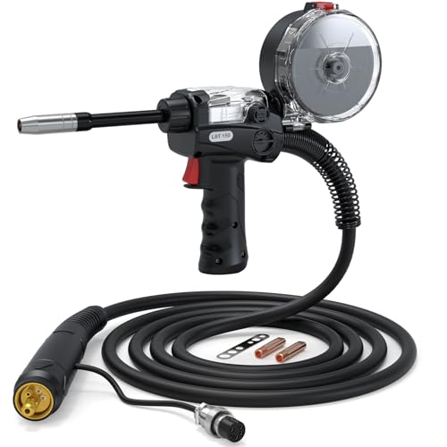
Smooth Wire Feeding: Experience seamless wire feeding with our spool gun. Featuring a 10-foot (3m) cable. Perfect fit for ARCCAPTAIN MIG205MP, MIG205PRO, MIG165PRO ensuring consistent and uninterrupted aluminum welding.

FACTORY-MATCHED SPOOL GUN FOR PLUG-AND-PLAY USE: Calibrated for RBM2000. Our 2026 upgrade eliminates parameter mismatch issues common to universal spool guns, delivering steady aluminum welding with simple setup.
Check These Requirements
- Gas connection: The machine needs a working gas solenoid, regulator connection, and suitable gun gas path.
- DCEP output: The electrode lead must be able to run positive for standard aluminum MIG.
- Spool-gun or push-pull compatibility: Confirm the exact gun model supported by the machine.
- Suitable output range: The machine must have enough amperage and duty cycle for the aluminum thickness and joint.
- Aluminum program or chart: Use a manufacturer-provided setup for the chosen wire diameter and alloy.
- Correct consumables: The gun needs the specified contact tip, nozzle, roll, guide, and liner.
A basic welder that has no gas valve, no spool-gun connection, fixed polarity, and no aluminum instructions is generally not a practical candidate. Replacing the machine or having the repair done professionally is safer than improvising a feed system.
Why MIG and TIG Are Better for Aluminum
MIG Welding Aluminum
MIG, also called GMAW, is usually the fastest practical choice for medium and thicker aluminum parts. It feeds a continuous solid aluminum electrode while argon protects the arc and molten weld pool.
Equipment You Need
- A MIG welder approved for aluminum and the material thickness
- A compatible spool gun, push-pull gun, or approved short push-only system
- U-groove drive rolls and nonmetallic wire guides when required
- A clean aluminum-compatible liner if the wire feeds through a conventional gun
- 100% argon for common shop aluminum MIG
- Solid ER4043, ER4943, ER5356, or another correctly selected filler
- A dedicated stainless steel brush and aluminum-only abrasives
- Clamps, PPE, and adequate fume extraction
Step-by-Step Aluminum MIG Setup
- Identify the base alloy. Look for a material stamp, drawing, manufacturer specification, or reliable documentation. Do not assume every silver-colored part is weldable aluminum.
- Check the machine manual. Confirm spool-gun compatibility, polarity, wire diameter, gas, output range, and starting parameters.
- Install the aluminum feed equipment. Fit the correct U-groove roll, contact tip, liner, guide, or spool gun. Keep drive pressure as low as practical.
- Set DCEP polarity. Follow the diagram in the machine manual rather than relying on the previous gasless-wire connection.
- Connect argon and check for leaks. Use the flow range stated by the gun and machine manufacturer. Excess flow can create turbulence and draw air into the shielding envelope.
- Clean the joint. Degrease first, allow the solvent to evaporate, and then remove oxide with a dedicated stainless brush or clean aluminum-only abrasive.
- Set voltage and wire speed from the chart. Match the chart to the exact wire alloy, diameter, joint, position, and metal thickness.
- Make a test weld. Use scrap of the same alloy and thickness. Cut or bend the test when joint strength matters.
- Use a 10° to 15° push angle. Point the nozzle in the direction of travel so shielding gas reaches the area ahead of the puddle.
- Keep moving as the part heats. Increase travel speed or pause between welds if the puddle begins to widen or the joint starts to sag.
- Fill the ending crater. Use the machine’s crater function or approved finishing technique to reduce termination cracking.
- Inspect the result. Look for porosity, cracks, incomplete fusion, excessive soot, undercut, and burn-through.
Pro Tip: Support the gun cable and keep it as straight as practical. Sharp bends increase drag on soft aluminum wire and can cause erratic feeding even when the drive-roll pressure is correct.
TIG Welding Aluminum
TIG, also called GTAW, gives you direct control over arc length, heat, and filler addition. It is often the better choice for thin sheet, small joints, cast-aluminum repairs, and work where appearance matters.
Most shop TIG welding on aluminum uses AC output with high-frequency or another noncontact starting system. Argon is the common shielding gas. Electrode type, diameter, AC balance, frequency, cup size, gas flow, amperage, and filler diameter must match the machine and job.
Basic Aluminum TIG Workflow
- Confirm that the machine provides an aluminum-capable AC TIG mode.
- Identify the base alloy and select a compatible filler.
- Degrease and remove oxide with dedicated tools.
- Fit and clamp the joint with a consistent gap.
- Set the machine from its aluminum chart or approved procedure.
- Test the arc and puddle on matching scrap.
- Keep a short, steady arc while adding clean filler to the leading edge of the puddle.
- Reduce heat or move faster as the part warms.
- Taper the current at the end and fill the crater.
- Inspect the weld after it has cooled naturally.
Do not assume that “one amp per thousandth of an inch” or a fixed 120–150 amp range will suit every joint. Aluminum alloy, joint mass, AC settings, fit-up, position, and machine design can change the required current.
Comparison Table: Flux Core vs. MIG vs. TIG for Aluminum
| Method | Best For | Advantages | Limitations | Equipment Needed |
|---|---|---|---|---|
| Standard self-shielded FCAW | Not recommended for aluminum | Useful on compatible steels | Common wire and flux are not suitable for aluminum | Do not use for aluminum unless a documented, classified industrial procedure specifically allows it |
| Aluminum MIG | Medium or thicker material, longer welds, and production | Fast, productive, and easier to automate | Needs argon and an aluminum-capable feed system | MIG power source, spool or push-pull gun, solid aluminum wire, and argon |
| Aluminum TIG | Thin material, precise joints, castings, and visible work | Excellent control and clean appearance | Slower and more skill-intensive | AC TIG welder, tungsten, filler rod, and argon |
| Aluminum brazing | Approved light-duty or noncritical joints | Can require less equipment and does not melt the base metal | Not equivalent to a fusion weld and may have lower service limits | Correct brazing filler, flux if required, heat source, and approved joint design |
Preparing Aluminum for Welding
Preparation is not optional. Aluminum oxide, oil, paint, moisture, shop dust, and steel particles can all cause defects.
How to Prep Aluminum
- Move solvent cleaning away from the welding area. Shut off ignition sources and follow the cleaner’s safety data sheet.
- Degrease before brushing. Use a clean lint-free cloth and an approved nonchlorinated cleaner. Brushing greasy metal can spread contamination across the joint.
- Let the cleaner evaporate fully. Never weld beside an open solvent container or on a wet surface.
- Remove oxide. Use a stainless steel brush reserved for aluminum or a clean aluminum-only abrasive.
- Clean both sides when possible. Contamination on the back of a full-penetration joint can enter the puddle.
- Clean the filler if required by its manufacturer. Store aluminum wire and rods in a clean, dry area.
- Weld soon after cleaning. Oxide begins reforming as soon as bare aluminum contacts air.
Warning: Never use chlorinated brake cleaner or another chlorinated solvent near welding heat or ultraviolet radiation. Use only a cleaner approved for the task, follow its safety data sheet, and allow all residue and vapor to clear before welding.
Joint Preparation and Fit-Up
The correct bevel, root opening, backing, and tack pattern depend on thickness, joint type, welding process, required penetration, and applicable code. A fixed 60° V-groove is not correct for every aluminum butt joint.
Use the joint design in the drawing, approved procedure, machine guidance, or applicable code. Avoid oversized gaps because aluminum can burn through quickly once the part becomes hot.
Common Mistake
Do not use a brush, file, flap disc, or grinding wheel that has touched carbon steel. Embedded steel can create inclusions, rust staining, and corrosion sites. Mark dedicated tools “Aluminum Only” and store them away from steel grinding dust.
Choosing the Right Filler Material
Filler selection starts with the exact base alloy. It also depends on joint strength, crack sensitivity, corrosion, service temperature, anodized appearance, ductility, and post-weld treatment.
Hobart’s aluminum filler-selection guide notes that 4043/4943 and 5356 cover many common weldments, but they are not interchangeable in every application.
| Filler | Common Reasons to Choose It | Important Limits |
|---|---|---|
| ER4043 | Fluid puddle, low shrinkage, reduced crack sensitivity on many 6xxx joints, bright appearance, and low smut | Not a universal choice for magnesium-rich 5xxx alloys; may provide lower ductility or strength than some alternatives |
| ER4943 | Similar welding characteristics to 4043 with improved strength in many suitable applications | Compatibility still depends on the base alloy and service requirements |
| ER5356 | Higher strength and ductility in many joints, better feedability, and closer anodized color match | Not recommended by Hobart for sustained service above 150°F; not correct for every alloy combination |
What About 5052 Aluminum?
5052 sits close to an important magnesium-content boundary. Some recognized charts allow either 4043-family or 5356 filler under specific conditions, while magnesium-richer 5xxx alloys normally require a compatible 5xxx filler.
Do not choose filler from a single anecdote. Check the exact alloy, temper, service temperature, strength requirement, corrosion environment, and manufacturer’s filler chart.
Alloys That Need Extra Caution
Many 1xxx, 3xxx, 5xxx, and 6xxx alloys can be fusion-welded with the correct procedure. However, some 2xxx and copper-bearing 7xxx alloys have high cracking or stress-corrosion risk.
Examples such as 2024 and 7075 are generally poor candidates for ordinary arc-weld repair. Some alloys within those series are weldable, so the series number alone is not enough. Unknown cast aluminum, wheels, heat-treated parts, and highly loaded components should be evaluated by a qualified specialist before welding.
Safety Considerations
Eye and Face Protection
Use a welding helmet and safety glasses that meet the requirements for the process. Do not rely on one fixed shade number for every aluminum weld. OSHA’s filter-lens guidance selects minimum protection by process and arc current.
Start with a shade that is too dark to see the weld area, then move lighter only as permitted by the equipment instructions and applicable safety guidance.
Fumes, Gases, and Ventilation
Welding can create metal fume, ozone, nitrogen oxides, and other gases. Coatings, oils, cleaners, and the base alloy can add further hazards.
OSHA’s welding-fume fact sheet advises keeping fumes out of your breathing zone and using adequate general or local exhaust ventilation. Welding outside does not automatically guarantee safe ventilation.
Argon is not toxic, but it can displace oxygen in an enclosed area. Do not weld in a tank, hull compartment, pit, or other confined space without a proper confined-space assessment and ventilation plan.
Clothing and Burn Protection
- Wear flame-resistant gloves, sleeves, clothing, and closed footwear.
- Cover exposed skin against ultraviolet radiation.
- Remove synthetic clothing that can melt against the skin.
- Use welding screens to protect nearby people from arc radiation.
- Handle recently welded parts with tools until their temperature is confirmed.
Fire and Electrical Safety
- Remove flammable liquids, paper, dust, fuel, and hidden combustibles.
- Keep a suitable fire extinguisher within reach.
- Inspect cables, the work lead, gas hose, regulator, and gun before use.
- Do not weld on a closed container or one that previously held fuel or chemicals.
- Follow the machine’s grounding, input-power, and duty-cycle instructions.
Practical Applications in the USA
Aluminum MIG and TIG are widely used in transportation, marine fabrication, construction, manufacturing, food equipment, and repair work. The correct process depends on the alloy, thickness, joint, production rate, and required quality.
Structural aluminum work may fall under AWS D1.2/D1.2M:2014 or another project-specific code. Code work can require approved joint details, a qualified welding procedure, qualified welders, material control, documentation, and inspection.
A hobbyist should not assume that a visually smooth bead proves a safe structural repair. A weld can look clean while still containing porosity, incomplete fusion, cracking, or an unsuitable filler mixture.
Repairs Best Left to a Qualified Shop
- Road wheels and motorcycle wheels
- Trailer tongues, couplers, suspension mounts, and structural frames
- Boat hulls below the waterline or highly stressed marine structures
- Pressure vessels, tanks, and pressure piping
- Aircraft and aerospace parts
- Ladders, lifting devices, fall-protection equipment, and scaffolding
- Unknown 2xxx or 7xxx alloy parts
- Cast parts with oil saturation, hidden cracks, or unknown service history
Troubleshooting Common Aluminum Welding Issues
| Problem | Likely Causes | What to Check |
|---|---|---|
| Porosity | Moisture, oil, oxide, gas leak, draft, damp filler, or excessive gun angle | Clean again, inspect gas connections, protect the arc from drafts, and verify gas flow |
| Burn-through | Excess heat, slow travel, wide gap, thin material, or accumulated heat | Use the correct program, increase travel speed, improve fit-up, and allow cooling between welds |
| Bird-nesting | Wrong roll, excessive pressure, dirty liner, long curved gun cable, or unsuitable feed system | Use U-groove rolls, reduce pressure, straighten the cable, and install a spool or push-pull gun |
| Black soot or smut | Poor gas coverage, pull angle, excessive arc length, contamination, or unsuitable filler | Use a slight push angle, check the nozzle and gas, clean the joint, and verify filler selection |
| Incomplete fusion | Cold start, oxide, restrictive joint, low output, poor torch position, or travel that is too fast | Clean the joint, use the approved starting parameters, correct joint access, and verify penetration on a test coupon |
| Crater crack | Stopping without filling the ending crater | Use crater-fill controls or taper the weld according to the approved procedure |
| Hot cracking | Wrong filler, crack-sensitive alloy, restrictive joint, excessive dilution, or poor crater control | Confirm the base alloy, use a filler chart, review joint design, and follow a qualified procedure |
| Wire shaving | Knurled rolls, too much roll pressure, sharp liner bends, or a damaged guide | Clean the feeder, install the specified aluminum parts, and reset pressure |
Which Method Should You Choose?
- You have a gasless-only flux-core welder: Do not try to weld aluminum with steel flux-core wire. Use another process or hire a shop.
- Your MIG machine supports a spool gun and argon: Aluminum MIG is often the most practical choice for general fabrication.
- The material is thin or appearance matters: Use an aluminum-capable AC TIG machine.
- The joint is light-duty and approved for brazing: Use a documented aluminum brazing consumable and joint design.
- The alloy is unknown: Identify it before applying heat.
- The part is structural or safety-critical: Use a qualified procedure and professional inspection.
Products Worth Considering

Perfect Compatibility: Designed specifically for LOTOS MIG225 MIG welders, this 9-foot spool gun ensures seamless integration and top-notch performance with your welding...
Conclusion
Welding aluminum with ordinary flux-core wire is not a difficult shortcut. It is the wrong process. Steel flux-core wire, gasless polarity, knurled rolls, drag technique, and slag-removal instructions do not become suitable for aluminum simply because an arc can be started.
For a true aluminum fusion weld, use a properly configured MIG system with solid aluminum wire and argon, or use an aluminum-capable AC TIG machine. Identify the alloy, select filler from a recognized chart, clean the metal in the correct order, and follow the machine manual or qualified welding procedure.
When the part carries people, pressure, road loads, lifting loads, or structural loads, stop treating the repair as a practice project. Have the alloy and joint evaluated by a qualified aluminum welding professional.
Frequently Asked Questions
Can I use a regular flux-core welder for aluminum?
A gasless-only flux-core welder normally cannot weld aluminum. A multiprocess MIG machine may work if it supports DCEP, argon, an approved spool or push-pull gun, suitable output, and the correct aluminum program.
Is aluminum flux-core wire real?
Flux-filled aluminum brazing consumables exist, but they are not automatically self-shielded FCAW electrodes for fusion welding. Check the product classification and data sheet before buying or using one.
Can I weld aluminum without shielding gas?
Not with ordinary MIG or TIG. Both normally need an inert shielding gas. Aluminum may be brazed with an approved flux-bearing filler, but brazing is not equivalent to a fusion weld.
Can steel flux-core wire stick aluminum together?
It may create an arc and leave material on the surface, but it will not produce a proper aluminum weld. The steel sheath and flux chemistry are incompatible with an aluminum joint.
What is the best method for thin aluminum?
AC TIG usually provides the most direct heat and puddle control for thin or appearance-sensitive aluminum. Pulsed MIG can also work when the machine, wire, joint, and operator are suited to the thickness.
Do I need a spool gun to MIG weld aluminum?
Not in every setup, but a spool gun or push-pull gun greatly reduces feeding problems. Some machines can push aluminum through a short gun with a suitable liner and U-groove rolls, but only when the manufacturer approves that setup.
Should I use ER4043 or ER5356?
The answer depends on the base alloy, required strength, crack resistance, service temperature, corrosion, and anodized appearance. Use a recognized filler-selection chart instead of choosing by wire availability alone.
Why do my aluminum MIG welds look dirty or porous?
Common causes include oxide, oil, moisture, poor gas coverage, leaks, drafts, a pull angle, excessive arc length, contaminated filler, or incorrect machine settings. Clean the joint, inspect the gas system, and test the setup on matching scrap.
Sources
- AWS A5.10/A5.10M:2023 — classification and scope of bare aluminum welding electrodes and rods
- AWS D1.2/D1.2M:2014 — structural aluminum welding requirements
- Miller: Welding Aluminum vs. Steel — cleaning, heat behavior, U-groove rolls, and aluminum wire feeding
- Miller: How to Successfully MIG Weld Aluminum — push angle, gun setup, and aluminum MIG technique
- Hobart Aluminum Filler Selection Guide — ER4043, ER4943, and ER5356 selection factors
- OSHA: Controlling Hazardous Fume and Gases During Welding — welding-fume hazards, ventilation, and exposure control