
Dual shield flux core welding, formally called gas-shielded flux-cored arc welding or FCAW-G, combines a tubular flux-cored electrode with an external shielding gas. It can produce high deposition rates, good sidewall fusion, and strong all-position performance on carbon and low-alloy steel when the wire, machine, gas, joint, and procedure are correctly matched.
The process is especially useful for thicker steel, heavy fabrication, structural work, equipment repair, railcar production, shipbuilding, and similar jobs. It is not a shortcut around joint cleaning, filler selection, preheat rules, welder qualification, or inspection. The exact wire data sheet and approved welding procedure specification, or WPS, always take priority over generic settings.
Quick Answer
Dual shield flux core welding uses tubular flux-cored wire plus external shielding gas. It works well for productive welding of thicker carbon and low-alloy steel, including many vertical and overhead jobs. Good results depend on matching the exact wire, gas, polarity, machine range, joint design, and approved WPS.
Key Takeaways
- “Dual shield” is the common shop name for gas-shielded flux-cored arc welding, or FCAW-G.
- The wire label and product data sheet determine the correct shielding gas, polarity, stickout, voltage, and wire-feed range.
- Common T-1, T-9, and T-12 gas-shielded wires normally use DCEP, but polarity must still be verified.
- Wire-feed speed, voltage, contact-tip-to-work distance, travel speed, and gas flow must be adjusted as a system.
- FCAW-G can increase deposition and out-of-position productivity, but it still requires slag removal and effective fume control.
- Structural or code-controlled work must follow the contract, current code, approved WPS, welder qualifications, and inspection plan.
At a Glance
| Time Required | About 20–30 minutes for a careful setup and test coupon; longer when changing liners, drive rolls, gas, or WPS parameters. |
| Difficulty | Intermediate. Basic wire-welding skills help, but vertical, overhead, structural, and code work require additional training and qualification. |
| Tools Needed | CV-capable welder, compatible feeder and gun, V-knurled rolls, approved FCAW-G wire, regulator/flowmeter, approved gas, work lead, PPE, ventilation, grinder, wire brush, chipping tool, and scrap coupons. |
| Cost | Variable. Wire, shielding gas, cylinder rental or ownership, drive rolls, gun consumables, input power, PPE, and fume control can cost more than a basic self-shielded setup. |
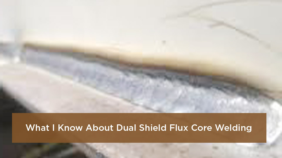
Image attribution in the original draft: Reddit.
Note: This guide explains general FCAW-G principles. It does not replace a manufacturer’s product data sheet, an approved WPS, engineering instructions, welder qualification, or the inspection requirements for structural, bridge, pressure-vessel, military, lifting, or safety-critical work.
What Is the Difference Between Dual Shield and Regular Flux Core Welding?
Regular flux core welding often means self-shielded FCAW, or FCAW-S. A self-shielded wire uses ingredients inside its tubular core to create the protection needed around the arc and weld pool. It does not require an external gas cylinder, making it useful for field work where shielding gas would be difficult to protect from wind.
Dual shield welding is FCAW-G. It also uses tubular wire, but the wire is designed to run with a specific external shielding gas. The flux provides functions such as slag formation, deoxidation, alloying, and arc stabilization, while the external gas helps protect the arc and molten weld metal from the atmosphere.
The name “dual shield” is a widely used shop term and an ESAB trade name, but it should not be interpreted as two interchangeable gas shields. FCAW-G wire must be used with the gas listed on its label or product data sheet. FCAW-S wire should not be connected to gas unless the wire manufacturer expressly approves that use.
| Feature | FCAW-G / Dual Shield | FCAW-S / Self-Shielded |
|---|---|---|
| External gas | Required and wire-specific | Normally not used |
| Wind tolerance | Sensitive to drafts; windscreen may be required | Better suited to exposed field work, subject to wire limits |
| Typical use | Shop fabrication, structural steel, shipbuilding, heavy equipment, railcar, and protected field work | Erection, outdoor repair, field construction, and remote work |
| Polarity | Common T-1, T-9, and T-12 wires normally use DCEP | Varies by wire; never assume all FCAW-S wires use the same polarity |
| Cleanup | Slag removal required between passes | Slag removal required between passes |
On heavy plate, FCAW-G can provide a high deposition rate and good out-of-position puddle control. That does not guarantee penetration, fusion, or inspection acceptance. Joint design, wire placement, heat input, work angle, travel angle, and procedure control still determine the result.
How Does Dual Shield Flux Core Welding Work?
FCAW-G is commonly run as a semiautomatic constant-voltage process. A wire feeder pushes the continuously supplied tubular electrode through the gun. The arc melts the wire and base metal, creating a weld pool that solidifies into the joint.
The material inside the wire is formulated for a particular classification and use. Depending on the product, it may contain slag-forming compounds, deoxidizers, alloying ingredients, arc stabilizers, and metal powders. The resulting slag covers the weld as it cools and must be removed before the next pass.
The external shielding gas flows through the gun nozzle. Common carbon-steel wires may be approved for 100% CO2, an argon/CO2 mixture, or both. The approved gas is shown by the product classification and manufacturer data. The Hobart Brothers guide to gas- and self-shielded wires notes that common gas-shielded wires often use either 100% CO2 or a 75%–80% argon balance with CO2.
Common E71T-1, E71T-9, and E71T-12 gas-shielded wires use DCEP and may support single- or multiple-pass welding. Smaller diameters are often available for all-position work, while larger diameters may be limited to flat and horizontal positions.
Low-hydrogen designators such as H4 or H8 describe the maximum diffusible hydrogen level demonstrated under specified test conditions. They do not mean the weld contains no hydrogen, and they do not remove the need for dry consumables, suitable preheat, proper heat input, and clean joints.
A .045-inch E71T-1C H8 gas-shielded wire can deposit about 8.9 pounds of wire per hour in flat-position test conditions, but actual deposition depends on the product, wire speed, current, position, operator, and approved procedure.
That productivity example comes from Hobart Brothers’ FCAW-G deposition comparison. It should not be treated as a guaranteed shop rate.
What Equipment Do You Need for Dual Shield Flux Core Welding?
Products Worth Considering
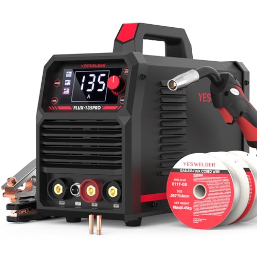
READY OUT OF THE BOX: Start welding immediately! It masterfully handles Gasless Flux Core MIG, Stick, and Lift TIG (Extra Lift TIG torch required). This budget-friendly 3-in-1 machine includes extra E71T-GS .030''&.035'' flux core wires, known for its smooth arc and high feedability. Say goodbye to heavy shielding gas cylinders—perfect for outdoor, windy, or all-position welding.

LARGE LED DIGITAL DISPLAY: The advanced digital display ensures crystal-clear visibilityeven in low-light environments, allowing welders to monitor parameters effortlessly. Its intuitive interface simplifies setup, it is easy to use with this welder machine.

MULTIFUNCTIONAL: A 4-in-1 welder, capable of Flux Core MIG/Gas MIG/ Stick/Lift TIG (need to purchase extra tig lift torch). This unit caters to a wide range of welding applications and meets your various welding needs.
CV-Capable Power Source
Use a constant-voltage power source that can operate inside the selected wire’s published voltage and wire-feed range. Check rated output and duty cycle, not only the machine’s maximum amperage. A machine that briefly reaches a required current may still be unsuitable for long production welds.
Portable multiprocess machines such as the Miller Multimatic 215 and Lincoln Power MIG 210 MP may run selected flux-cored wires, but they are not 250-amp-plus production systems. Miller lists the Multimatic 215 with an output range up to 230 amps, while Lincoln rates the Power MIG 210 MP at 200 amps and 24 volts at a 25% duty cycle on 230-volt input. Verify the exact machine manual, gun rating, wire diameter, and intended duty cycle before loading FCAW-G wire.
Compatible Wire Feeder and Drive Rolls
Use the feeder and drive-roll type specified by the equipment maker. V-knurled rolls are commonly used for gas- and self-shielded flux-cored wires because they grip the tubular wire without requiring excessive tension. Excess pressure can deform the wire, create shavings, damage the liner, and contribute to birdnesting.
Correct Gun, Liner, Tip, and Nozzle
The gun must be rated for the expected amperage and duty cycle. Long, high-current welds may require a heavier air-cooled gun or a water-cooled system. Match the liner, contact tip, diffuser, and drive-roll groove to the wire diameter. Keep the nozzle and diffuser clear enough to maintain even shielding-gas coverage.
Shielding-Gas System
Use a secured cylinder, suitable regulator or flowmeter, sound hose, and the exact gas approved for the wire. Cylinder size is a supply and portability choice rather than a welding parameter. A small cylinder may be convenient for occasional work, while production use normally requires a larger or manifolded supply.
Preparation and Safety Equipment
- Helmet with a lens shade suitable for the arc current and task
- Safety glasses with side protection under the helmet
- Flame-resistant clothing, welding gloves, and suitable boots
- Local exhaust ventilation or a fume-extraction system
- Hearing protection where noise exposure requires it
- Angle grinder, approved abrasive wheels, wire brush, chipping tool, and measuring tools
- Fire-resistant screens, extinguisher, and fire-watch provisions where needed
Startup cost varies widely. A shop that already owns a suitable CV power source and feeder may need only consumables, drive rolls, gas, and fume control. A complete industrial setup can cost far more than a basic portable welder, so a fixed “under $2,000” estimate is not dependable.
Engine-driven welders such as a Miller Bobcat can provide welding output or auxiliary power for a compatible feeder. They do not create shielding gas. FCAW-G still requires a separate approved gas cylinder or bulk supply, regulator, hose, and wind protection.
Pro Tip: Before buying wire, compare its full operating table with the machine’s rated output, feeder speed range, gun duty cycle, available input power, and approved gas. This prevents loading a wire that the system can feed but cannot run at a useful duty cycle.
Step-by-Step Guide to Setting Up Your Machine for Dual Shield Welding
- Identify the job requirements. Confirm the base-metal grade, thickness, joint type, position, required mechanical properties, governing code, and approved WPS. Do not weld unidentified high-strength, cast, coated, pressure-containing, or safety-critical material based only on appearance.
- Select the correct wire. Match the filler classification to the base metal, design strength, toughness, service temperature, shielding gas, position, and code requirements.
- Read the product data sheet. Record the required polarity, approved gas, gas-flow range, wire diameter, contact-tip-to-work distance, voltage range, wire-feed range, positional limits, and storage instructions.
- Confirm equipment capacity. Verify power-source output, feeder speed, drive rolls, gun rating, contact tip, liner, work lead, input circuit, and duty cycle.
- Load the wire correctly. Install the proper V-knurled rolls, cut the wire end cleanly, guide it through the inlet and liner, and apply only enough roll pressure to feed without slipping.
- Set polarity and gas. Common T-1, T-9, and T-12 FCAW-G wires normally use DCEP, meaning electrode positive and work negative. Verify the spool label before connecting leads. Attach the approved gas and leak-test fittings with a suitable leak-detection solution.
- Set initial parameters. Use the manufacturer’s chart or the approved WPS. Do not copy a voltage and wire speed from a different brand, gas, diameter, position, or classification.
- Set CTWD and gun angle. Contact-tip-to-work distance is wire-specific. Many .045-inch products use a value near 1/2 to 3/4 inch, but the published range controls. Use a slight drag angle unless the wire data or WPS directs otherwise.
- Run a test coupon. Use matching scrap, thickness, position, joint preparation, and backing conditions. Check arc stability, bead shape, toe wetting, slag release, porosity, undercut, and fusion.
- Record the final setup. Log wire lot, gas, flow, polarity, voltage, wire speed, CTWD, travel speed, preheat, interpass temperature, and observed result.
Warning: Never treat a generic internet setting as authorization for structural, bridge, pressure-vessel, lifting, military, pipeline, or other code-controlled work. Use the approved WPS and stop when the material, joint, consumable, or acceptance requirement is uncertain.
Best Practices and Machine Settings for Dual Shield Flux Core Welding
FCAW-G settings work as a system. Changing one control may change current, arc length, heat input, deposition, penetration profile, slag behavior, and gas coverage.
| Control | Main Effect | Common Problem When Incorrect |
|---|---|---|
| Wire-feed speed | Strongly influences current and deposition on a CV system | Too low may cause an unstable, long arc; too high may stub the wire or overload the puddle |
| Voltage | Changes arc length, bead width, and toe wetting | Too high may cause undercut, spatter, or worm tracking; too low may create a narrow, convex bead |
| CTWD | Changes electrical resistance and actual welding current | Excessive distance may reduce current and gas coverage; too little may overheat the tip or cause burnback |
| Travel speed | Controls bead size and heat input per unit length | Too fast may cause undercut or lack of fusion; too slow may cause overlap, excessive reinforcement, or excess heat input |
| Gas flow | Maintains shielding around the arc and molten pool | Too low may cause porosity; too high may create turbulence and draw surrounding air into the shield |
| Work and travel angles | Direct the arc and control toe tie-in and slag position | Poor angles may cause uneven legs, undercut, slag inclusions, or incomplete fusion |
Gas flow is not automatically 30 CFH. Product sheets for some gas-shielded wires specify ranges around 35–50 CFH, while other products and shop conditions may differ. Use the wire maker’s range and adjust only for the approved nozzle, gas, draft conditions, and procedure.
Use a drag or pull technique for normal FCAW work unless the manufacturer or WPS directs otherwise. A small travel angle often provides good visibility and helps keep slag behind the arc. Avoid the contradictory practice of switching between a 15-degree drag and a 15-degree push without a procedure-based reason.
Clean slag completely between passes. Remove paint, oil, moisture, heavy scale, and loose rust before welding. FCAW-G may tolerate minor surface conditions better than some solid-wire procedures, but flux is not a replacement for required joint preparation.
Preheat and interpass temperature are not chosen only by plate thickness. The American Welding Society’s preheat guidance explains that steel chemistry, thickness, filler-metal hydrogen level, heat input, and joint restraint can all affect the requirement. Follow the WPS, code table, engineer, and steel producer’s instructions.
Practice coupons are useful, but a shop bend test is not a substitute for a qualified procedure or required inspection. For production work, test methods and acceptance criteria must come from the drawing, contract, code, engineer, or quality plan.
Common Mistakes in Dual Shield Flux Core Welding and How to Fix Them
- Wrong polarity: Verify the spool label and data sheet before welding. A T-1 FCAW-G wire commonly requires DCEP, but other cored wires may differ.
- Wrong shielding gas: Do not assume every wire accepts both CO2 and 75/25. Using an unapproved gas can change arc behavior, chemistry, strength, and classification.
- Excess drive-roll pressure: Reduce tension and use the specified V-knurled groove. Check the liner and inlet guides for wire shavings.
- Excessive voltage: Return to the manufacturer or WPS range. High voltage can contribute to undercut, spatter, and worm tracking.
- Incorrect CTWD: Measure from the contact tip to the work, not from the nozzle. Hold it consistently within the wire’s published range.
- Skipped slag removal: Chip and brush every pass. Grind only when the procedure permits or when defects must be completely removed.
- Wide uncontrolled weave: Keep bead width within the WPS and wire maker’s limit. Excessive weaving can trap slag and raise heat input.
- Ignoring duty cycle: Watch power-source and gun ratings. Stop when thermal protection activates or when the rated duty cycle requires cooling.
- Welding over contamination: Do not add 10% amperage to compensate for rust, oil, moisture, or paint. Clean the joint and return to the approved range.
- Pushing the gun by habit: FCAW commonly uses a drag technique. Use another travel direction only when supported by the wire instructions or WPS.
Pros and Cons of Dual Shield Flux Core Welding
| Aspect | Advantages | Limitations |
|---|---|---|
| Deposition Rate | Can deposit filler quickly and reduce arc time on suitable thick-steel joints | High-output procedures require a capable power source, feeder, gun, input circuit, and duty cycle |
| Fusion and Puddle Control | Can provide good sidewall tie-in and a controllable out-of-position puddle | Does not guarantee penetration or eliminate the need for correct joint design and wire placement |
| All-Position Capability | Many smaller-diameter T-1, T-9, and T-12 wires support flat, horizontal, vertical-up, and overhead work | Position limits vary by classification, wire diameter, and product |
| Weld Properties | Available with defined tensile, toughness, and diffusible-hydrogen classifications | Properties depend on approved gas, parameters, heat input, base metal, and test conditions |
| Cost Efficiency | Higher deposition can reduce labor and the number of stops compared with stick welding | Wire, gas, ventilation, slag cleanup, and heavier equipment add cost |
| Ease of Use | Stable arc and fast-freezing slag can help trained operators make consistent welds | Fumes, slag, CTWD sensitivity, wind, and parameter interactions still require skill and control |
Dual shield is often a strong choice for structural and heavy-fabrication work where deposition and positional capability matter. For thin cosmetic panels, clean sheet metal, or jobs where slag removal is undesirable, solid-wire MIG may be a better fit.
When Should You Use Dual Shield Flux Core Welding?
Consider FCAW-G when the job involves thicker carbon or low-alloy steel, substantial weld volume, multiple passes, or vertical-up and overhead welding in a protected environment. It is commonly used for beams, frames, stiffeners, gussets, heavy equipment, railcars, ship structures, storage vessels, and similar fabrication.
Do not select it only because the material is rusty or because deep penetration is assumed. The process still needs clean enough material, a suitable joint, correct filler strength, approved gas, proper heat input, and verified fusion.
Use FCAW-S or another field process when a reliable shielding-gas envelope cannot be maintained. A windscreen may make FCAW-G practical outdoors, but changing to straight CO2 does not make the process windproof. Even light drafts can disturb gas coverage.
Solid-wire GMAW can be preferable for thin sheet, low-spatter cosmetic work, automated clean-steel production, or joints where slag would slow production. Stick welding remains useful where portability, access, and simple equipment matter more than continuous-wire deposition.
For weathering steel, quenched-and-tempered steel, HY-series steel, abrasion-resistant plate, castings, or unknown repairs, select filler and preheat only after identifying the material and reviewing the engineer or manufacturer’s requirements.
Real-World Applications of Dual Shield Flux Core Welding in the USA
Manufacturer-listed FCAW-G applications include construction, structural and bridge fabrication, shipbuilding, offshore work, railcars, heavy equipment, general fabrication, and pressure or storage vessels. These uses explain why the process is common in production shops and protected field environments.
In practical U.S. terms, that can include structural fabrication in Chicago, shipyard work in Louisiana, railcar production in Pennsylvania, agricultural frames in Idaho, trailer fabrication in Texas, and offshore work along the Gulf Coast. Geography does not change the technical requirements: the drawing, material, WPS, gas, consumable, qualification, and inspection plan still control.
Repair facilities serving equipment brands such as John Deere or Caterpillar may use FCAW-G on suitable steel components, but brand familiarity does not identify the base metal or authorize a repair. Boom arms, chassis parts, cast components, and lifting equipment may require engineering instructions, crack removal, preheat, controlled heat input, postweld treatment, or nondestructive examination.
Specialized low-alloy wires are available for high-strength steels. For example, ESAB Dual Shield II 110 is marketed for steels including HY-100. That does not make a general E71T-1 wire suitable for naval work or allow military welding outside an approved procedure.
Pressure vessels, pipelines, submarine components, bridge members, and radiographically inspected joints cannot be assumed acceptable because FCAW-G was used. Root quality, fusion, mechanical properties, and inspection acceptance depend on the complete welding procedure and quality system.
Safety Considerations for Dual Shield Flux Core Welding
Warning: FCAW-G produces intense arc radiation, hot slag, sparks, fumes, noise, electric-shock hazards, and compressed-gas hazards. Do not weld in a confined or poorly ventilated space without a formal hazard assessment, atmospheric controls, trained personnel, and the required rescue provisions.
Welding fumes contain metal particles, and mild-steel fumes commonly include manganese. The NIOSH welding-fume guidance warns that inhaled manganese is a concern because it bypasses normal digestive defenses and may affect the lungs and nervous system.
Keep your head out of the plume and capture fumes near the source with local exhaust ventilation or a fume-extraction gun where practical. General shop air movement alone may not control the welder’s breathing-zone exposure. Respirators must be selected for the actual hazard and used within an appropriate respiratory-protection program; a generic dust mask is not an automatic solution.
Wear a welding helmet and filter shade suitable for the current, wire diameter, and task. Use safety glasses under the helmet, flame-resistant clothing, gauntlet gloves, suitable boots, and hearing protection where required. Protect nearby workers with noncombustible welding screens while maintaining ventilation.
Secure shielding-gas cylinders against falling. Protect the valve, move cylinders with a suitable cart, keep them away from excessive heat and impact, and follow the gas supplier’s handling instructions. Close the cylinder valve when the system is not in use and inspect hoses and fittings for damage.
Remove combustible materials from the hot-work area or shield them from sparks and slag. Maintain a fire watch when required and check hidden spaces, floor openings, walls, and the opposite side of the work for smoldering material.
Follow OSHA 29 CFR 1910.252 and the rules applicable to the worksite. Do not weld near vapors from chlorinated degreasers or solvents. Ultraviolet radiation from gas-shielded welding can react with certain vapors and create highly toxic decomposition products.
Inspect the gun, work lead, electrode cable, feeder, input cord, plugs, and connections before use. Keep gloves and clothing dry, insulate yourself from the work and ground where required, and follow the machine manual and applicable electrical code rather than improvising outlet or grounding arrangements.
Comparing Dual Shield Flux Core to Other Welding Processes
| Process | Where It Excels | Main Trade-Off |
|---|---|---|
| FCAW-G / Dual Shield | High-deposition thick-steel fabrication and many out-of-position joints | Requires gas protection, slag removal, and strong fume control |
| FCAW-S | Outdoor erection, field repair, and remote work | Wire-specific technique, smoke, slag, and sometimes lower deposition than comparable FCAW-G |
| Solid-Wire GMAW | Clean steel, thin material, low cleanup, automation, and cosmetic work | Gas-sensitive and may provide less out-of-position puddle support at high deposition rates |
| SMAW / Stick | Portability, access, repair, and simple field equipment | Frequent electrode changes and lower continuous arc time |
| GTAW / TIG | Precise roots, thin material, alloy work, and controlled high-quality welds | Lower deposition and slower fill rates |
| Submerged Arc | Very high deposition on long flat or horizontal production welds | Limited positional versatility and greater equipment complexity |
A TIG root followed by FCAW-G fill and cap passes can be useful on approved pipe procedures, but it is not automatically suitable for every pipe material, diameter, service, or code. Select the process combination through procedure qualification and project requirements.
Dual shield is also not inherently stronger than MIG, stick, or TIG. Strength is determined by the filler classification, deposited weld properties, base metal, joint design, fusion, heat input, workmanship, and acceptance criteria.
Step-by-Step Guide to Welding a Fillet Joint with Dual Shield
The following method is appropriate for a practice T-joint or for work covered by an approved WPS. Do not transfer these steps to a structural connection without confirming joint size, position, material, preheat, filler, and inspection requirements.
- Confirm the joint design. A normal fillet weld usually joins two surfaces without a 45-degree bevel. Beveling, root openings, backing, or partial-joint-penetration details must come from the drawing or WPS.
- Prepare the surfaces. Remove paint, oil, moisture, loose rust, heavy scale, and burrs from the weld area. Clean far enough from the joint to prevent contamination from entering the puddle.
- Fit and tack the joint. Set the angle, gap, alignment, and tack size required by the drawing or procedure. Do not assume every joint uses tacks four inches apart.
- Set preheat when required. Measure the temperature with an approved method and maintain the specified interpass range.
- Set the machine from the WPS or wire chart. Confirm DCEP where required, gas type, flow, voltage, wire-feed speed, and CTWD.
- Set the work angle. For an equal-leg T-joint, begin near 45 degrees between the two members. Adjust only as needed to compensate for joint orientation or unequal leg requirements.
- Use a controlled drag angle. Keep the arc near the leading edge of the puddle and the slag behind it. Avoid excessive whipping.
- Deposit the first pass. Use a steady stringer or the bead pattern permitted by the WPS. Watch both toes for equal tie-in.
- Stop correctly. Fill the crater as required by the procedure. Use run-on or run-off tabs only when the joint design or WPS specifies them.
- Clean and inspect. Remove slag completely. Check bead size, contour, undercut, overlap, porosity, arc strikes, cracks, and visible fusion before adding another pass.
- Add fill or cap passes. Maintain the allowed bead width, interpass cleaning, temperature, and sequence. Do not bury a defect under the next pass.
For vertical-up practice, reduce the puddle size only within the approved operating range. Pause long enough at each toe to achieve tie-in, but do not use a wide weave that traps slag or exceeds the permitted bead width.
Choosing the Right Filler Wire for Dual Shield Welding
The filler classification is more useful than choosing by brand alone. A common carbon-steel designation such as E71T-1C/M H8 can be read as follows:
- E: Electrode.
- 7: Minimum tensile-strength class of 70 ksi under the specification.
- 1: All-position capability for the classified diameter and conditions.
- T: Tubular, flux-cored electrode.
- -1: Usability designator covering characteristics such as polarity, pass capability, and slag system.
- C: Classified with 100% CO2.
- M: Classified with an approved mixed shielding gas.
- H4 or H8: Optional diffusible-hydrogen limit in milliliters per 100 grams of deposited weld metal.
- J or other toughness designators: Additional impact-property requirements under the applicable AWS specification.
E71T-1 is not the correct answer for every mild-steel job. Match filler strength and toughness to the base metal and design. An undermatching or overmatching filler can create problems depending on joint restraint, fatigue loading, service temperature, and heat treatment.
For low-alloy, weathering, quenched-and-tempered, HY-80, HY-100, abrasion-resistant, or creep-resistant steel, use the filler called out by the engineer, steel producer, repair manual, code, or qualified procedure. “E80T-something” is not a complete selection method.
Check the gas suffix carefully. Some wires accept both 100% CO2 and a mixed gas, while others are approved for only one gas family. Changing gas can alter penetration profile, arc character, manganese and silicon recovery, mechanical properties, and classification.
ESAB Dual Shield is a gas-shielded flux-cored family. Hobart FabCO products are also gas-shielded flux-cored wires. Hobart Fabshield products are generally self-shielded wires, so “Fabshield” should not be used as a generic dual-shield recommendation.
Store wire in a clean, dry area in its original packaging until needed. Protect mounted spools from condensation, dust, grinding debris, oil, and temperature swings. If wire becomes wet, rusty, dirty, or questionable, quarantine it and follow the manufacturer’s written reconditioning or disposal instructions. Do not invent a 250°F baking cycle.
Products Worth Considering

E71T-GS FLUX CORE WIRE: This self-shielding, AWS E71T-GS flux-cored wire excels due to its advanced core design, delivering exceptional arc stabilization and high feedability for effortless welding. The core also incorporates powerful deoxidizing agents, ensuring clean, reliable welds even when welding through light rust or mill scale.

Welding Easy and Quick: AWS E71T-GS 030” Flux Core welding wire (The actual Net Weight of Wire is 2LB), no need for shielding gas, install it then you can welding all positions, single and multi pass welding. Great for T-joints, butt welds & lap welds.

E71T-11 FLUX CORE WIRE: Known for its smooth arc action and minimal spatter, it operates efficiently without the need for external shielding gas, making it ideal for outdoor use or drafty environments where gas-shielded processes might struggle. This electrode offers excellent slag removal and good weld penetration.
Preparing Joints for Optimal Dual Shield Welds
Joint preparation must match the required weld type and procedure. A butt joint might use a square groove, single-V, double-V, bevel groove, backing, or open root depending on thickness, access, process, and required penetration. There is no universal 30- to 60-degree bevel or 1/16-inch root gap.
Remove oil, grease, moisture, paint, plating, heavy rust, and scale from the weld zone. Confirm whether coated steel contains zinc, lead, chromium, cadmium, or another hazardous material before heating it. Coating removal can create its own dust and exposure hazards.
Fit-up controls weld quality. Verify root opening, groove angle, land, alignment, member angle, backing, tack size, and distortion control against the drawing or WPS. Magnets and clamps can help hold a practice joint, but they do not replace dimensional checks.
Preheat may be required to slow cooling, reduce hydrogen-cracking risk, or satisfy the WPS. It is not automatically 100–200°F on every half-inch plate. Measure preheat at the specified distance and maintain the required interpass temperature throughout the weld sequence.
Use enough tacks to maintain fit-up without creating excessive restraint. Tacks incorporated into the finished weld must meet the procedure requirements and be cleaned, shaped, or removed when defective.
Advanced Techniques for Out-of-Position Dual Shield Welding
FCAW-G often performs well vertical-up and overhead because its slag system helps support the molten metal. That advantage still depends on using an all-position wire within the manufacturer’s positional parameter range.
For vertical-up fillets, use a controlled travel speed and keep the arc directed into the leading edge of the puddle. A small weave or triangle pattern may be acceptable when the WPS allows it, but excessive width increases heat input and the risk of trapped slag.
For overhead welding, keep the puddle small and maintain a consistent CTWD. Reduce voltage or wire-feed speed only within the approved range. Wear full protective clothing because hot slag and spatter can fall into cuffs, pockets, footwear, and helmet areas.
Avoid improvised “cough,” whip, or repeated arc-breaking techniques unless they are specifically supported by the wire manufacturer and procedure. A steady arc is easier to reproduce and inspect.
Six-G practice is relevant when the qualification or production work involves fixed pipe. Plate qualifications use different positions and test arrangements. Train for the exact process, position, backing condition, diameter, thickness, and code required by the work.
Do not assume pulse mode improves a T-1 dual-shield wire. Most common rutile FCAW-G wires are designed for conventional constant-voltage operation and may not gain a benefit from pulsing. Certain wires and manufacturer-developed programs can be exceptions, so use pulse only when the power-source program, wire maker, and WPS support it.
Troubleshooting Porosity and Other Weld Imperfections
| Problem | Likely Causes | Corrective Action |
|---|---|---|
| Porosity | Low or turbulent gas flow, drafts, leaks, blocked nozzle, excessive CTWD, damp wire, dirty joint, wrong gas | Stop welding, verify gas and flow, leak-test the system, clean the nozzle and joint, protect the arc from drafts, and remove defective weld metal before repair |
| Worm tracking | Excess voltage, moisture, contaminants, incorrect stickout, unsuitable parameter balance | Return to the wire chart, reduce voltage only within the approved range, verify CTWD, and replace questionable wire |
| Slag inclusion | Poor cleaning, low heat at the sidewall, wrong angle, excessive weave, bad bead placement | Remove the defect completely, clean each pass, correct arc placement and angle, and use the permitted bead width |
| Undercut | Excess voltage, high travel speed, wrong work angle, oversized weave, poor toe pause | Correct the parameter balance and angle, reduce travel speed as permitted, and maintain controlled toe tie-in |
| Lack of fusion | Poor wire placement, low heat input, excessive travel, bad joint design, heavy scale, oversized puddle | Remove the defect, clean and verify the joint, direct the arc at the fusion face, and use the qualified range |
| Excess spatter | Wrong voltage-to-wire-speed balance, wrong gas, excessive CTWD, poor work connection, contaminated tip or liner | Verify gas and polarity, restore chart settings, clean consumables, and improve the work connection |
| Birdnesting | Excess roll pressure, wrong drive roll, blocked liner, kinked gun cable, mismatched tip | Release the rolls, clear damaged wire, inspect the liner and tip, straighten the cable, and reset minimum effective tension |
| Cracking | Hydrogen, wrong filler, hard base metal, inadequate preheat, excessive restraint, poor crater fill, unacceptable heat input | Stop work, determine the cause, remove the full crack, verify material and procedure, and obtain engineering or welding-supervisor approval before repair |
Visual checks can reveal surface defects, but they cannot prove internal fusion or mechanical properties. Bend tests, macroetches, ultrasonic testing, magnetic-particle testing, radiography, or other methods must be performed and interpreted under the applicable procedure and acceptance standard.
Wrapping Up
Dual shield flux core welding can be one of the most productive processes for thicker steel and out-of-position fabrication. Its real advantages come from the combination of a suitable flux-cored wire, approved shielding gas, controlled slag system, capable equipment, correct joint preparation, and repeatable technique.
The main lesson is not to memorize one amperage, voltage, gas flow, or preheat temperature. Start with the contract and code, follow the approved WPS and wire data sheet, verify equipment capacity, run a representative coupon, and record the final setup.
Clean every pass, keep the gas shield stable, control CTWD and travel angle, and stop when porosity, cracking, fusion problems, or unexplained arc changes appear. Use run-on and run-off tabs, crater-fill programs, backing, or special bead sequences only when the joint design or procedure calls for them.
Frequently Asked Questions
Is Dual Shield Flux Core Welding Suitable for Beginners?
A beginner with basic wire-welding skills can learn FCAW-G on flat practice coupons. The setup has more variables than self-shielded hobby welding because the operator must control gas, polarity, CTWD, slag, wire-feed speed, voltage, and joint preparation. Vertical, overhead, structural, and code work require supervised training and qualification.
Can You Use Dual Shield Welding Outdoors?
Yes, but only when the shielding-gas envelope can be protected. Use a suitable windscreen and monitor the weld for porosity. Some manufacturer guidance recommends a windscreen when breeze exceeds about 5 mph, but even lighter drafts can cause trouble around corners or large structures. FCAW-S is usually better for exposed work.
What Is the Best Shielding Gas for Dual Shield Flux Core?
There is no universal best gas. Use the gas printed on the wire label and product data sheet. Many carbon-steel wires accept 100% CO2, a 75%–80% argon balance with CO2, or both. Other wires are classified for only one mixture. Gas choice can change arc behavior, penetration profile, spatter, chemistry, and mechanical properties.
How Do You Avoid Worm Tracking in Dual Shield Welds?
Keep voltage, wire-feed speed, CTWD, and gas inside the manufacturer’s recommended range. Protect the wire from moisture and clean oil, rust, and other contaminants from the joint. If worm tracks appear, stop and correct the cause instead of covering them with another pass.
Is Dual Shield Flux Core Stronger Than MIG Welding?
Not inherently. Both flux-cored and solid-wire filler metals are available in defined strength classes. Finished weld strength depends on filler classification, base metal, joint design, fusion, heat input, procedure, workmanship, and inspection. FCAW-G may be more productive or easier to control out of position, but that does not automatically make it stronger.
What Polarity Does Dual Shield Wire Use?
Common E71T-1, E71T-9, and E71T-12 gas-shielded wires normally use DCEP, meaning the wire is positive and the work is negative. Always verify the spool label because polarity can differ among other cored-wire classifications.
How Much Stickout Should You Use for Dual Shield Welding?
Use the contact-tip-to-work distance specified by the wire manufacturer or WPS. Many .045-inch gas-shielded wires operate near 1/2 to 3/4 inch, but the correct value varies with wire design, diameter, current, position, and contact-tip recess. Measure from the contact tip, not the end of the nozzle.
Can Dual Shield Weld Thin Sheet Metal?
Some small-diameter wires can weld relatively thin steel, but FCAW-G is generally better suited to thicker material and higher deposition work. On automotive panels and other thin sheet, solid-wire MIG usually offers easier heat control, less slag, and less cleanup. Follow the wire’s minimum-thickness and operating guidance.
Sources
- American Welding Society — AWS D1.1/D1.1M:2025-AMD1 — current structural-steel welding code scope, qualifications, inspection, and acceptance framework.
- American Welding Society — Preheat and Interpass Guidance — factors affecting preheat, including steel composition, thickness, hydrogen, and restraint.
- Hobart Brothers — Weldability of Gas- and Self-Shielded Flux-Cored Wires — gas types, polarity, classifications, positions, and wire-selection principles.
- Hobart Brothers — How to Weld With Gas-Shielded Flux-Cored Wires — setup sequence and manufacturer-data-sheet guidance.
- OSHA — 29 CFR 1910.252 Welding, Cutting, and Brazing — fire prevention, PPE, ventilation, cleaning compounds, and workplace safety.
- NIOSH — Welding Fumes and Manganese — welding-fume composition, manganese exposure, and worker-health guidance.


[…] you’re new to this, don’t sweat it. Flux core arc welding, or FCAW, is like MIG’s tougher cousin. Instead of solid wire and gas, you spool up a tubular […]