Early in the shop, grabbing the wrong spool of flux-cored welding wire taught me a hard lesson about porosity, spatter, and weak beads. The label matters: some wires are made for general carbon-steel repair, some for code-controlled structural work, and others for stainless steel, low-alloy steel, nickel alloys, or hardfacing.
The right wire changes the required polarity, shielding gas, usable welding positions, pass limits, heat input, and mechanical properties. It also has to match your feeder, gun, power source, base metal, joint design, and the code or welding procedure specification that governs the job.
This guide explains the main flux-cored welding wire types, how to read common classifications, how to choose a diameter and setup, and how to avoid the mistakes that lead to porosity, slag inclusions, poor fusion, and unnecessary cleanup.
Quick Answer
Choose flux-cored wire by base-metal chemistry, required strength and toughness, welding position, indoor or outdoor conditions, wire diameter, machine capacity, polarity, shielding gas, and code requirements. Never assume all self-shielded wire uses the same settings or that every gas-shielded wire accepts the same gas mixture.
Image by wileymetal
Key Takeaways
- FCAW-S is self-shielded and portable; FCAW-G needs the exact external gas listed by the wire manufacturer.
- The AWS classification identifies more than tensile strength. It can also indicate position, usability, gas, impact toughness, and diffusible-hydrogen requirements.
- Polarity, stickout, voltage, wire-feed speed, pass limits, and gas are wire-specific. Start with the spool label and technical data sheet.
- Flux tolerates some mill scale and surface contamination, but it is not a substitute for cleaning paint, oil, heavy rust, plating, or hazardous coatings.
- Structural, seismic, bridge, piping, and pressure-vessel work must follow the applicable code, approved WPS, and qualification requirements.
At a Glance
| Time Required | About 10–20 minutes to identify the wire and set up the machine; welding time depends on the joint. |
| Difficulty | Beginner for basic mild-steel practice; advanced for code work, alloy selection, and multi-pass procedures. |
| Tools Needed | Wire data sheet, compatible welder and feeder, correct drive rolls and contact tip, work clamp, cleaning tools, scrap steel, and full welding PPE. |
| Cost | Varies by alloy, spool size, shielding gas, consumables, and whether a qualified procedure or inspection is required. |
What Is Flux-Cored Welding Wire?
Flux-cored arc welding wire is a continuously fed tubular electrode. Its metal sheath carries current and becomes filler metal, while the core contains fluxing, deoxidizing, alloying, and arc-stabilizing ingredients. The exact core chemistry depends on the classification and intended use.
There are two process families. In self-shielded flux-cored arc welding, or FCAW-S, ingredients in the core create the shielding system needed around the molten weld pool. In gas-shielded flux-cored arc welding, or FCAW-G, the wire still produces slag, but an external shielding gas is also required. Both forms normally leave slag that must be removed after the weld and between passes.
The slag protects and shapes the cooling bead, but it does not automatically prevent cracking. Crack resistance depends on base-metal chemistry, filler-metal selection, hydrogen control, joint restraint, preheat, heat input, and the approved welding procedure.
Note: Metal-cored wire is also tubular, but it is not the same as flux-cored wire. Metal-cored products generally rely on external gas and are designed to leave little or no slag.
Types of Flux-Cored Welding Wire
The two broad types are self-shielded and gas-shielded. Within those groups, wires are further separated by base-metal family, strength level, welding position, impact toughness, hydrogen designation, shielding gas, polarity, and whether they are approved for single-pass or multi-pass welding.
Products Worth Considering

Welding Easy and Quick: AWS E71T-GS 030” Flux Core welding wire (The actual Net Weight of Wire is 2LB), no need for shielding gas, install it then you can welding all positions, single and multi pass welding. Great for T-joints, butt welds & lap welds.
FEATURES: There is a flux core inside the flux-cored wire that stabilizes the arc, enhances operating performance, and provides protection. This design results in less spatter and produces high-quality welds.

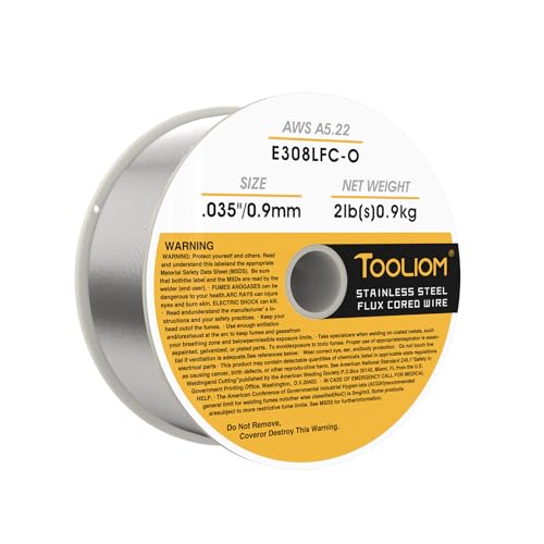
High Quality & Reliable Welds: VEVOR 0.03" 2 lbs E308LFC-O flux core MIG welding wire provides stable arc action with low spatter for smooth, clean weld beads. Compatible with 304 and 304L stainless steel for strong, consistent weld beads
Gas-Shielded vs. Self-Shielded Flux-Cored Wire
| Feature | Gas-Shielded FCAW-G | Self-Shielded FCAW-S |
|---|---|---|
| Shielding | Requires the gas listed on the wire data sheet | Does not use an external shielding-gas cylinder |
| Best setting | Shop, fabrication line, or protected field enclosure | Field work, portable repair, and conditions where gas coverage is difficult |
| Wind sensitivity | Gas coverage can be disrupted by drafts or wind | More wind-tolerant, but the arc and fume plume still need control |
| Typical polarity | Commonly DCEP, but the product data sheet controls | Often DCEN for T-8 and T-11 wires, but some FCAW-S products use DCEP |
| Slag and fume | Produces slag; fume level depends on wire and parameters | Produces slag and often a heavier visible fume plume |
| Common strengths | High deposition rates, good sidewall fusion, smooth operation in the right parameter window | Portability, no gas cylinder, and reliable shielding outdoors |
| Main caution | The wrong gas or poor gas coverage can cause porosity and change weld properties | Technique, stickout, voltage, and storage can have a narrow acceptable range |
Gas-shielded wire is often the better choice for controlled shop production on thicker steel because it can run smoothly at high deposition rates. Self-shielded wire is valuable for outdoor repair and erection because it removes the gas cylinder and hose from the setup. Neither type is automatically “cleaner,” “stronger,” or cheaper on every job.
Common Carbon-Steel Usability Classifications
The current carbon-steel filler-metal specification is AWS A5.20/A5.20M:2025. Modern labels may use a longer open classification system, while many shops still recognize familiar usability designators such as T-1, T-8, and T-11.
| Common Label | What It Usually Tells You | Typical Use | Do Not Assume |
|---|---|---|---|
| E71T-11 | 70 ksi class, all-position, self-shielded usability type | General carbon-steel fabrication, maintenance, and portable repair | Unlimited plate thickness or unlimited multi-pass use; check the product limits |
| E71T-8 | 70 ksi class, all-position, self-shielded structural usability type | Structural field welding when the wire, WPS, and qualifications meet the job requirements | That every T-8 wire has identical impact properties, stickout, or parameter ranges |
| E71T-1C or E71T-1M | 70 ksi class, all-position, gas-shielded usability type; C and M identify the gas used for classification | Shop fabrication, heavy equipment, structural work, and multi-pass welds under an approved procedure | That 100% CO2 and every argon/CO2 blend are interchangeable |
| E70T-1 | The “0” position digit differs from E71T-1 and generally limits welding position | Flat groove and horizontal fillet applications when permitted by the data sheet | That it is an all-position substitute for E71T-1 |
| E71T-GS | General-purpose, self-shielded, typically single-pass wire | Light repair and hobby work within the manufacturer’s stated limits | That it is suitable for code work or unrestricted multi-pass welding |
How to Read a Flux-Cored Wire Label
In a familiar label such as E71T-11, “E” means electrode, “7” represents a 70 ksi tensile-strength class, “1” indicates all-position usability, “T” means tubular, and “11” is the usability designator. The usability portion carries important information about shielding method, polarity, pass limits, and operating characteristics.
Longer classifications may add gas, impact-toughness, diffusible-hydrogen, and other supplemental designators. Do not decode a wire from a shortened retailer listing alone. Read the spool label, the manufacturer’s technical data sheet, and the applicable AWS specification. Lincoln Electric’s flux-cored usability designator guide provides a practical overview.
Wire Types for Different Materials
| Base Material or Task | Wire Family | Selection Priority |
|---|---|---|
| Mild and carbon steel | Carbon-steel FCAW wire under AWS A5.20 | Strength, position, gas, polarity, pass limits, toughness, and code acceptance |
| High-strength low-alloy steel | Low-alloy FCAW wire under the applicable AWS A5.29 classification | Match the approved WPS, base-metal group, required tensile properties, impact toughness, and hydrogen limits |
| Stainless steel | Stainless cored wire under AWS A5.22 | Match the stainless grade, corrosion service, ferrite requirements, position, gas, and procedure |
| Nickel alloys | Nickel-alloy cored wire under AWS A5.34 | Use the exact alloy and procedure required for temperature and corrosion service |
| Build-up and hardfacing | Surfacing or hardfacing cored wire | Select for wear mode, base-metal compatibility, number of layers, cracking tendency, and machining needs |
| Aluminum | Normally bare aluminum MIG or TIG wire, not ordinary steel FCAW wire | Choose an aluminum filler such as an appropriate ER4xxx or ER5xxx alloy using the equipment and process recommended for the joint |
For aluminum, the normal consumable family is bare MIG or TIG wire classified under AWS A5.10/A5.10M:2023. Do not load carbon-steel flux-cored wire into a machine and attempt to weld aluminum with it.
Choosing the Right Flux-Cored Wire for Your Project
I choose wire in a fixed order so I do not get distracted by spool price or a familiar brand name. The selection starts with the job requirements and ends with the machine setup.
Products Worth Considering

E71T-GS FLUX CORE WIRE: This self-shielding, AWS E71T-GS flux-cored wire excels due to its advanced core design, delivering exceptional arc stabilization and high feedability for effortless welding. The core also incorporates powerful deoxidizing agents, ensuring clean, reliable welds even when welding through light rust or mill scale.

E71T-GS FLUX CORE WIRE: This self-shielding, AWS E71T-GS flux-cored wire excels due to its advanced core design, delivering exceptional arc stabilization and high feedability for effortless welding. The core also incorporates powerful deoxidizing agents, ensuring clean, reliable welds even when welding through light rust or mill scale.

E71T-GS FLUX CORE WIRE: This self-shielding, AWS E71T-GS flux-cored wire excels due to its advanced core design, delivering exceptional arc stabilization and high feedability for effortless welding. The core also incorporates powerful deoxidizing agents, ensuring clean, reliable welds even when welding through light rust or mill scale.
1. Identify the Base Metal
Confirm the material grade rather than guessing from appearance. Mild steel, quenched-and-tempered steel, stainless steel, galvanized steel, cast material, and tool steel can require very different filler metals and procedures. A magnet or spark test is not enough for critical work.
2. Check the Required Strength and Toughness
Matching tensile strength is only one part of filler selection. Low-temperature service, cyclic loading, hydrogen control, corrosion, post-weld heat treatment, and design requirements may control the choice. A 70 ksi-class filler is not automatically wrong for every higher-strength base metal, and an overmatching filler is not automatically better. Follow the engineered WPS.
3. Confirm the Welding Position
All-position wires use a slag system that supports the puddle in vertical and overhead welding. Flat and horizontal wires can often be run at higher deposition rates, but they should not be used out of position unless the classification and procedure allow it.
4. Match the Shielding Method to the Work Area
Use FCAW-S when portability and wind tolerance matter. Use FCAW-G when you can protect the arc and want the operating characteristics of a gas-shielded product. A windbreak can still improve self-shielded welding by stabilizing the arc and keeping the fume plume away from the operator.
5. Choose a Diameter the Machine Can Run
Smaller diameters such as 0.030 or 0.035 inch are common on compact machines and lower-current work. Diameters such as 0.045 inch and 1/16 inch support higher deposition rates when the power source, feeder, gun, duty cycle, and joint can handle them. Diameter alone does not set a safe material-thickness range.
Check the machine’s output chart, feeder range, contact-tip size, liner, drive rolls, gun rating, available input power, and duty cycle. Tubular wire can be crushed by excessive drive-roll pressure, so use the roll style and tension recommended by the equipment and wire manufacturer.
6. Verify Polarity, Gas, and Pass Limits
Do not use “self-shielded equals DCEN” as a universal rule. Many T-8 and T-11 wires use DCEN, while other self-shielded classifications use DCEP. Gas-shielded FCAW commonly uses DCEP, but the spool label controls.
The gas designation also matters. Some wires are classified for 100% CO2, some for a specified argon/CO2 mix, and some products are approved for either. The wrong gas can change arc behavior, penetration, spatter, chemistry, and mechanical properties.
Pro Tip: Photograph the spool label before loading the wire. The photo gives you a quick record of classification, heat or lot information, polarity, gas, and recommended parameter range after the spool is inside the feeder.
Applications and Uses of Flux-Cored Wire
Flux-cored wire is common in structural fabrication, heavy equipment, shipbuilding, rail work, agricultural repair, machinery, and general fabrication because it can provide high deposition rates and strong sidewall fusion. The process is especially useful where long welds or out-of-position work make stick-electrode changes inefficient.
For a trailer, rack, mower frame, or farm repair, the useful wire may be a general-purpose carbon-steel product. For stainless food equipment, exhaust, chemical service, or high-temperature parts, the filler must match the alloy and service conditions. Hardfacing wire is for restoring worn surfaces, not automatically for joining tool steel.
Code work needs a separate level of control. AWS D1.1/D1.1M:2025 covers welded steel structures when invoked by the contract. AWS D1.8/D1.8M:2025 supplements D1.1 for seismic force-resisting systems. Bridge welding is covered by AASHTO/AWS D1.5M/D1.5:2025, not D1.8.
For petrochemical piping, pressure vessels, and other critical service, the applicable construction code, owner specification, WPS, procedure qualification, welder qualification, preheat, interpass control, inspection, and testing determine whether a wire is acceptable. External gas by itself does not “ensure integrity.”
Step-by-Step Guide to Flux-Cored Welding
This setup sequence works as a safe starting framework. The actual numbers must come from the wire data sheet, machine chart, and approved WPS.
Step 1: Read the Spool and Data Sheet
Confirm the complete classification, diameter, polarity, shielding gas, position, pass limits, storage instructions, and recommended voltage and wire-feed-speed range. For code work, confirm that the exact manufacturer, trade name, classification, diameter, and lot controls meet the WPS and project documents.
Step 2: Prepare the Joint
Remove oil, paint, moisture, heavy rust, scale, and plating from the weld area. Clean the work-clamp location to bare metal. Bevel and gap the joint according to the drawing or WPS rather than relying on a universal 60-degree groove or fixed lap overlap.
Step 3: Configure the Feeder and Gun
Install the correct drive rolls, liner, contact tip, and nozzle. Set only enough drive-roll pressure to feed without slipping. Check the gun and work cables for damage, tighten connections, and confirm that the power source and gun have enough amperage and duty-cycle capacity.
Step 4: Set Polarity and Gas
Connect the electrode lead exactly as the wire requires. For FCAW-G, install the specified gas, check for leaks, set flow according to the data sheet and nozzle, and protect the arc from drafts. Do not substitute a convenient gas blend unless the product documentation and WPS permit it.
Step 5: Set Voltage, Wire-Feed Speed, and Stickout
On a constant-voltage wire feeder, wire-feed speed strongly affects welding current, while voltage affects arc length and bead shape. Start inside the manufacturer’s range for the diameter, position, and joint. A stickout near 3/4 inch is common for some general-purpose flux-cored wires, while T-8 products may call for about 1 to 1-1/4 inches. Use the product value, not a universal rule.
Step 6: Run a Test Coupon
Use scrap of the same grade, thickness, joint type, and position. Listen for a steady arc and inspect bead profile, toe wetting, slag release, penetration, and visible discontinuities. Adjust one variable at a time within the approved range.
Step 7: Weld With a Controlled Drag Angle
A drag or pull technique is standard for slag-producing wire. A work angle that bisects the joint and a travel angle of roughly 5–15 degrees are common starting points, but joint access and the data sheet control. Keep travel speed steady and avoid wide, uncontrolled weaving.
Step 8: Remove Slag and Inspect
Chip and brush all slag between passes. Look for cracks, porosity, undercut, overlap, incomplete tie-in, arc strikes, and trapped slag. A bead that looks smooth is not proof of adequate fusion, so critical welds must receive the inspection and testing required by the job.
Warning: Never use generic internet settings for a load-bearing, pressure-retaining, lifting, vehicle-suspension, roll-cage, bridge, or seismic weld. Use an approved joint design and WPS, and have the work performed and inspected by qualified personnel.
Tips for Using Flux-Cored Wire Effectively
- Keep the wire dry: Store it in the original sealed packaging in a dry, enclosed area. Let cold wire warm to shop temperature before opening it so condensation does not form.
- Do not rebake spooled wire in a rod oven: Tubular wire and its spool can be damaged by heating. Follow the wire manufacturer’s storage and exposure limits.
- Use a clean feed path: Grinding dust, oil, rust, and excess drive-roll pressure can cause erratic feeding and arc instability.
- Maintain stickout: Self-shielded wires can be sensitive to changes in electrical stickout because it changes resistance heating and welding current.
- Clean between passes: Slag left at the toes or root can become an inclusion in the next pass.
- Use a windbreak wisely: It can stabilize the work area outdoors, but never create a poorly ventilated pocket that traps welding fume around your head.
- Record successful settings: Note wire lot, diameter, polarity, gas, voltage, wire-feed speed, stickout, position, and travel speed for repeatable non-code shop work.
Hobart’s self-shielded flux-core wire guidance explains why storage, technique, and the different operating needs of T-8 and T-11 wires matter.
Common Mistakes and How to Avoid Them
| Problem | Likely Causes | What to Check |
|---|---|---|
| Porosity | Contamination, damp wire, wrong gas, gas leaks, wind, excessive stickout for that wire, or poor joint access | Clean and dry the joint; verify gas, polarity, flow, hose condition, stickout, and wire storage |
| Worm tracks or surface pockmarks | Moisture pickup, excessive voltage, unsuitable stickout, or running outside the product window | Use dry wire and return to the manufacturer’s voltage and stickout range |
| Slag inclusions | Slag not removed, poor bead placement, narrow groove, low heat input, wrong travel angle, or excessive weaving | Clean every pass, improve access, place stringers correctly, and stay within the WPS |
| Lack of fusion or cold lap | Low current, fast travel, wrong work angle, poor joint prep, too small a machine, or an unsuitable wire | Verify wire-feed speed, voltage, machine output, bevel, work angle, and procedure |
| Burn-through | Excess heat input, slow travel, large root opening, oversized wire, or thin material | Use a suitable process and wire, reduce heat within the allowed range, shorten arc time, and improve fit-up |
| Excess spatter | Wrong polarity, voltage outside the range, poor work-lead connection, unstable feed, contamination, or wrong gas | Check the label, cables, drive rolls, contact tip, gas, and settings |
| Erratic feeding or burnback | Wrong tip or liner, crushed tubular wire, excess roll tension, worn consumables, tangled spool, or blocked gun | Correct the feed path and replace damaged consumables |
| Undercut | High voltage, fast travel, wrong angle, excessive weaving, or poor pause at the toes | Return to the procedure range and improve bead placement |
One of the easiest mistakes is reversing polarity after switching between solid MIG wire and self-shielded flux core. Another is treating all self-shielded spools as interchangeable. I now check the label before touching the leads or controls.
Machine Settings and Joint Preparation Suggestions
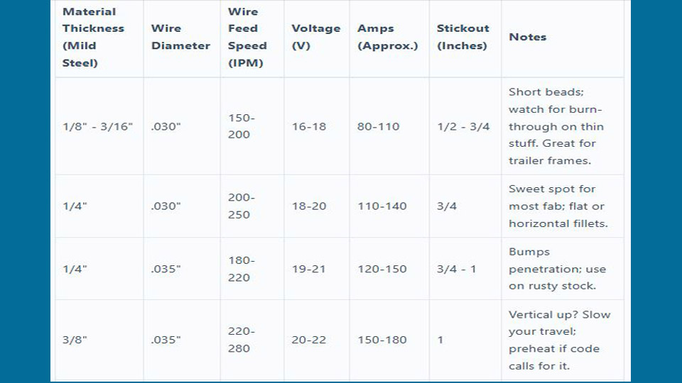
There is no reliable universal chart for “0.045-inch wire on 1/4-inch steel” because two wires with the same diameter can require different polarity, gas, voltage, wire-feed speed, stickout, and pass limits. Use the product data sheet and machine chart as the starting point.
| Variable | What It Changes | Best Practice |
|---|---|---|
| Wire-feed speed | Strongly influences amperage and deposition rate on a CV machine | Set within the data-sheet range for wire diameter and position |
| Voltage | Changes arc length, bead width, wetting, and spatter | Fine-tune after wire-feed speed; avoid exceeding the wire’s range |
| Electrical stickout | Changes resistance heating, current, penetration, and arc behavior | Measure from the contact tip and use the value specified for the wire |
| Shielding gas | Affects transfer, penetration profile, spatter, chemistry, and mechanical properties | Use only the gas and flow range approved for the wire and WPS |
| Travel speed | Changes bead size, heat input, fusion, and slag behavior | Keep a consistent puddle and stay within procedure limits |
| Joint preparation | Controls root access, fusion, distortion, and required weld volume | Use the drawing or WPS; clean to sound metal and maintain fit-up |
For a butt joint, the bevel angle, root face, root opening, backing, preheat, and weld sequence should come from the joint design. For lap and fillet joints, overlap and weld size should come from the drawing or engineering requirement. A fixed “1/2-inch minimum overlap” is not a safe rule for every thickness or load.
Pros and Cons of Flux-Cored Welding
Advantages
- High deposition potential and fewer starts than stick welding on long welds
- Good sidewall fusion and useful out-of-position options
- Self-shielded portability for field work
- More tolerance for mill scale and minor surface contamination than many solid-wire setups
- Wide selection of carbon-steel, low-alloy, stainless, nickel-alloy, and surfacing products
Disadvantages
- Slag removal is required, including between passes
- Fume generation can be high, especially without effective source capture
- Wire costs more per pound than common solid wire in many markets
- Some products have narrow parameter, storage, pass, or thickness limits
- Gas-shielded FCAW adds cylinders, regulators, hoses, and wind protection
- Thin cosmetic sheet metal is often easier with an appropriate solid-wire MIG or TIG process
The cheapest spool is not always the lowest-cost wire. Total cost includes deposition rate, arc-on time, gas, slag removal, rework, qualification, and inspection.
Safety Considerations in Flux-Cored Welding
Flux-cored arc welding produces hazardous fumes and gases. Use local exhaust or another effective ventilation method that captures fume near the source without disturbing required gas shielding. Keep your head out of the plume. OSHA’s welding, cutting, and brazing requirements address ventilation, fire prevention, confined spaces, and other controls.
- Wear a welding helmet with the proper shade, safety glasses with side shields, flame-resistant clothing, leather gloves, and suitable boots.
- Remove combustible material and maintain the fire watch and extinguisher required for the work area.
- Inspect the electrode cable, gun, work lead, work clamp, feeder, and power cord before use. The work clamp completes the welding circuit; it is not a substitute for electrical safety or equipment grounding.
- Do not weld on sealed tanks, drums, lines, or containers unless they have been properly cleaned, isolated, vented, and declared safe under an approved procedure.
- Identify coatings and base metals before welding. Stainless steel, galvanized coatings, lead paint, cadmium plating, and other materials can create additional hazards.
- Keep chlorinated solvents and their vapors away from arc welding. Heated or UV-exposed chlorinated residues can form highly toxic decomposition products.
- Use respiratory protection only when selected for the hazard and used within a compliant respiratory-protection program. A disposable mask is not a substitute for fume control.
- Treat confined-space welding as specialized work requiring atmospheric testing, ventilation, rescue planning, and the applicable permit procedure.
Warning: Never clean a weld area with brake cleaner or another chlorinated solvent before arc welding. Use a welding-compatible cleaning method, allow all approved cleaner to evaporate, and follow the product safety data sheet.
Advanced Techniques With Flux-Cored Wire
Advanced FCAW work is less about tricks and more about controlling heat input, bead placement, and slag. Vertical-up and overhead welds usually use stringers or tightly controlled manipulation so each bead supports the next. Wide weaving can trap slag and exceed procedure limits.
Multi-pass welds require a planned sequence. Clean every pass, place beads to avoid deep slag pockets, control interpass temperature, and use the bead size and heat input allowed by the WPS. Terms such as “hot pass” and “cooler cap” are not universal instructions for pressure work.
Some modern power sources offer pulsed or waveform-controlled FCAW programs. Use them only with a wire, feeder, gas, and procedure approved by the equipment and consumable manufacturers. A pulse button does not make a thick-wire process suitable for auto-body sheet metal.
For FCAW-G, changing from CO2 to an argon/CO2 blend may smooth the arc and change penetration, but the gases are not freely interchangeable. Use only a gas covered by the wire classification and WPS.
Cost Efficiency and Flux-Cored Wire
Flux-cored wire can save labor when its deposition rate, out-of-position capability, and long arc-on time reduce starts and total welding time. It can also cost more when a small job does not benefit from those strengths or when slag removal, fume control, gas, and rework dominate the schedule.
Self-shielded wire removes shielding-gas cost and handling in the field. Gas-shielded wire may improve production in a controlled shop. Bulk packaging reduces spool changes, but only when the feeder, storage system, lot control, and wire consumption justify it.
I have seen FCAW beat stick welding clearly on long heavy-fabrication welds, but I no longer attach a universal labor-savings percentage to the process. The honest comparison is job-specific: pounds of acceptable weld metal per labor hour, including setup, cleaning, inspection, and repairs.
Wrapping It Up
Flux-cored welding wire selection comes down to more than choosing “gas” or “gasless.” Start with the base metal and service requirements, then verify classification, strength, toughness, position, pass limits, polarity, shielding gas, diameter, machine capacity, and storage condition.
For ordinary repair work, a correctly applied general-purpose carbon-steel wire may be all you need. For structural, seismic, bridge, stainless, low-alloy, piping, pressure, or hardfacing work, the governing code and approved WPS decide what is acceptable.
Run a test coupon before the real joint, keep the wire dry, clean between passes, and stop when the bead shows a problem you cannot explain. Fixing the setup before continuing is faster and safer than grinding out a long defective weld.
Frequently Asked Questions
What is the difference between gas-shielded and self-shielded flux-cored wire?
Gas-shielded FCAW wire requires the external shielding gas listed by the manufacturer. Self-shielded FCAW wire creates its shielding system from ingredients in the core and does not use an external gas cylinder. Both normally produce slag, and both must be run with the specified polarity and parameters.
When should I use flux-cored wire instead of solid MIG wire?
Flux-cored wire is often useful on thicker steel, longer welds, out-of-position work, field repairs, and material with mill scale. Solid MIG wire is often easier on thin, clean sheet where low spatter, no slag, and a smooth appearance matter. The machine, joint, environment, and procedure should decide.
How do I choose the right flux-cored wire diameter?
Choose a diameter that falls within the power source, feeder, gun, contact-tip, and duty-cycle ratings and that provides the deposition rate and positional control the joint needs. Smaller compact machines commonly use 0.030- or 0.035-inch wire, while industrial work often uses 0.045 inch or larger.
What are common flux-cored welding mistakes for beginners?
Common mistakes include wrong polarity, assuming every wire uses the same stickout, skipping the spool data sheet, poor cleaning, excessive drive-roll pressure, using the wrong gas, failing to remove slag between passes, and continuing after porosity or poor fusion appears on a test coupon.
Is flux-cored wire suitable for stainless steel projects?
Yes, when you use a stainless flux-cored classification that matches the base metal, corrosion service, shielding gas, position, and approved procedure. Carbon-steel E71-series wire is not a substitute for stainless filler metal.
Can I weld aluminum with ordinary flux-cored wire?
No. Ordinary carbon-steel or stainless flux-cored wire is not compatible with aluminum. Aluminum is normally welded with a suitable bare aluminum MIG or TIG filler alloy and equipment designed to feed soft aluminum wire.
What is the difference between E71T-GS and E71T-11?
E71T-GS is generally a single-pass, general-purpose self-shielded wire. E71T-11 is an all-position self-shielded classification that may permit limited multi-pass work, subject to the product’s stated thickness and pass limits. Neither should be assumed acceptable for code work without verification.
Can I use the same polarity and gas for every flux-cored wire?
No. Polarity and gas are part of the wire’s operating requirements. Many T-8 and T-11 wires use DCEN, many gas-shielded wires use DCEP, and some self-shielded classifications use DCEP. Gas-shielded products may be approved for CO2, a specific mixed gas, or both. Follow the exact label and data sheet.
Sources
- AWS A5.20/A5.20M:2025 — current carbon-steel flux-cored electrode classification requirements.
- AWS D1.1/D1.1M:2025 — structural steel welding scope, WPS, qualification, fabrication, and inspection framework.
- Miller: Flux-Cored Welding Basics — process types, setup, wire diameter, stickout, preparation, and technique.
- Lincoln Electric: Flux-Cored Electrode Usability Designators — classification and usability-code interpretation.
- Hobart Filler Metals: Self-Shielded Flux-Core Wire — T-8 and T-11 use, technique, stickout, and storage guidance.
- OSHA 29 CFR 1910.252 — ventilation, fire prevention, confined-space, and welding-safety requirements.