Welding cast iron with flux core is possible, but it is not the same as running ordinary self-shielded steel wire on mild steel. Cast iron contains much more carbon, has low ductility, and can crack as the weld and heat-affected zone expand and contract. A sound repair depends on identifying the casting, choosing a cast-iron filler, controlling heat, and following the wire manufacturer’s procedure.
This guide explains a practical workflow for noncritical repairs such as some machine bases, housings, brackets, and antique tools. Safety-critical, pressure-retaining, lifting, towing, steering, suspension, brake, and high-value engine repairs need an engineer-approved welding procedure and qualified inspection.
Quick Answer
Yes, cast iron can be welded with flux core, but only with a cast-iron filler such as an AWS A5.15 ENiFeT3-CI wire and a procedure matched to the casting and wire. Ordinary E71T steel wire, universal settings, and uncontrolled heating or cooling greatly raise the risk of cracking.
Key Takeaways
- Use filler metal classified for cast iron, not common E71T mild-steel flux-core wire.
- Polarity, wire size, position, preheat, amperage, voltage, and stickout are product-specific.
- Remove oil, paint, rust, and the full crack before welding; flux does not replace proper cleaning.
- Choose either a qualified hot-weld or low-heat repair method and control cooling.
- Do not use a hobby repair on a part whose failure could injure someone.
At a Glance
| Time Required | About 1–3 hours of active work, plus controlled cooling and inspection time |
| Difficulty | Advanced; practice on matching scrap before repairing the part |
| Tools Needed | Compatible wire-feed welder, cast-iron flux-cored wire, grinder, stainless or dedicated wire brush, clamps, temperature tools if required, PPE, ventilation, and inspection supplies |
| Cost | Varies widely; specialized wire, heat-control equipment, and inspection can cost more than replacing a small casting |
Warning: Do not rely on a DIY flux-core repair for a trailer hitch, lifting point, steering or suspension part, brake component, pressure vessel, fuel-contaminated casting, or any part whose failure could cause injury. Use a qualified welding engineer, an approved procedure, and specified nondestructive testing.
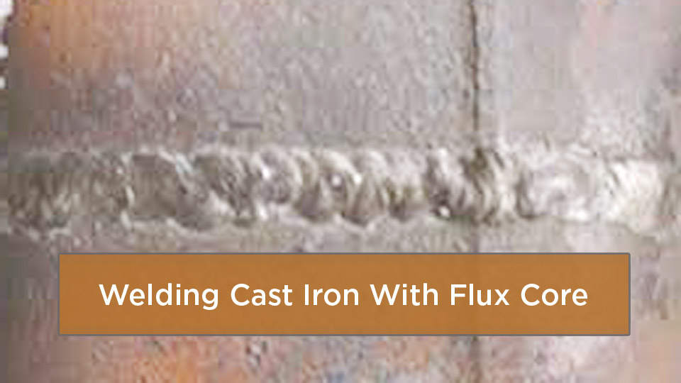
Image by weldingweb
Affiliate disclosure: This article contains an Amazon affiliate link. If you buy through it, the site may earn a commission at no extra cost to you.
Can You Weld Cast Iron With Flux Core?
Yes, but the answer depends on the type of iron, the filler metal, the joint, and the service load. The current AWS A5.15 specification covers filler metals for flux-cored arc welding of gray, malleable, nodular, compacted-graphite, and certain alloy cast irons. That does not mean every casting is a good repair candidate.
Specialized self-shielded nickel-iron flux-cored wire can work well for production repair, buildup, and some field repairs. However, many of these wires are larger and require more output than a small 120-volt hobby welder can supply. They may also be limited to flat or near-flat positions.
Before striking an arc, compare the replacement cost, the chance of hidden cracking, and the consequence of failure. A low-value, noncritical bracket may be worth attempting. A cracked engine block, press frame, towing component, or pressure housing usually belongs with a specialist.
Cast Iron and Why It Is Tricky to Weld
Cast iron is a family of iron-carbon alloys, not one single metal. Many common grades contain roughly 2%–4% carbon. Gray iron contains graphite flakes; ductile iron has rounded graphite nodules; malleable and compacted-graphite irons have different structures and properties. White iron contains hard carbides and is generally much harder to repair successfully.
In gray iron, the sharp ends of graphite flakes act as local stress raisers. Welding also creates steep temperature changes. The molten area can cool into hard, brittle structures, while contraction places the surrounding casting in tension. That combination explains why a bead can look acceptable while hot and crack minutes or hours later.
The goal is not maximum heat or maximum penetration. The goal is enough fusion with the lowest practical restraint, dilution, and thermal shock for the selected filler and procedure.
Oil-soaked castings add another problem. Lubricant can remain in pores and emerge as the metal heats, causing porosity and lack of fusion. Paint, plating, rust, and old repair metal can also change fume hazards and weld behavior.
Identify the Casting and Decide Whether to Repair It
Start by finding the casting mark, manufacturer drawing, service manual, or material certificate. A spark test, fracture appearance, file test, and drilling behavior can provide clues, but they are not a substitute for positive material identification when the part is critical.
- Gray cast iron: Common in machine bases, housings, manifolds, and older tools. It is brittle in tension and often repaired with nickel or nickel-iron filler.
- Ductile iron: Stronger and tougher than gray iron, but welding can damage the heat-affected zone and local ductility if the procedure is wrong.
- Malleable or compacted-graphite iron: Requires filler and heat control matched to the grade and service.
- White or highly alloyed iron: Often a poor candidate for field welding; consult the casting manufacturer or a repair specialist.
- Cast steel: Not cast iron. It normally requires a steel welding procedure based on its chemistry and strength.
Note: If the crack reaches a machined bore, sealing surface, coolant or oil passage, threaded boss, or highly restrained corner, the repair may require machining, pressure testing, and qualified NDT after welding.
Flux Core Welding Basics for Beginners
Flux-cored arc welding, or FCAW, uses a continuously fed tubular electrode. Some wires are self-shielded and need no external gas. Others are gas-shielded, often called dual-shield wire. The exact shielding method, polarity, electrical range, and stickout come from the wire data sheet.
The flux can form shielding gas, slag, and deoxidizing products, but it does not make dirty cast iron weldable. Oil, rust, paint, moisture, and slag between passes still cause porosity, inclusions, and weak fusion. Clean metal and a properly opened joint are essential.
Do not assume that common E71T-11 or E71T-GS mild-steel wire is a suitable substitute. Those wires are designed for carbon-steel applications and do not provide the nickel-rich deposit commonly selected to control cracking and dilution in cast-iron repairs.
Choosing the Right Flux Core Wire for Cast Iron Repairs
Look for a product that explicitly lists the cast-iron grades and repair type. One recognized AWS classification is ENiFeT3-CI under AWS A5.15. It is a nickel-iron flux-cored electrode classification, but products within that class can still have different operating instructions.
For example, the Midalloy MASTERCOR ENiFe-CI data sheet lists a 55% nickel deposit, flat-position use, preheating, slow cooling, and light peening after each weld. It also states that the deposit is hard and not easily machined. By contrast, the Welding Alloys CAST NICI-O data sheet lists DC positive, limited welding positions, no required preheat for that product, and a typical hardness of 150 HB.
That difference is why a generic instruction such as “always preheat to 500°F” or “always use DCEP” is not a complete procedure. Follow the current package label, safety data sheet, technical data sheet, and qualified WPS for the exact wire.
Pro Tip: Buy the filler before planning the machine setup. Specialized cast-iron wire may come only in industrial spool sizes and diameters that your feeder, gun, contact tip, and power source cannot handle.
Products Worth Considering

E71T-GS FLUX CORE WIRE: This self-shielding, AWS E71T-GS flux-cored wire excels due to its advanced core design, delivering exceptional arc stabilization and high feedability for effortless welding. The core also incorporates powerful deoxidizing agents, ensuring clean, reliable welds even when welding through light rust or mill scale.

E71T-GS FLUX CORE WIRE: This self-shielding, AWS E71T-GS flux-cored wire excels due to its advanced core design, delivering exceptional arc stabilization and high feedability for effortless welding. The core also incorporates powerful deoxidizing agents, ensuring clean, reliable welds even when welding through light rust or mill scale.

Welding Easy and Quick: AWS E71T-GS 030” Flux Core welding wire (The actual Net Weight of Wire is 2LB), no need for shielding gas, install it then you can welding all positions, single and multi pass welding. Great for T-joints, butt welds & lap welds.
Essential Equipment for Flux Core Welding on Cast Iron
- Compatible constant-voltage wire-feed power source: It must support the wire diameter, output range, duty cycle, and polarity required by the filler manufacturer.
- Correct feeder parts: Use the drive-roll style, liner, contact tip, and gun rating specified for the wire. Tubular wire can be damaged by excessive roll pressure.
- Cleaning and joint-prep tools: Grinder, carbide burrs, dedicated brush, clean files, and solvent approved for hot-work preparation.
- Heat-control tools: A furnace, induction heater, heating blanket, or rosebud may be required by the procedure, along with temperature crayons, contact probes, or a suitable infrared instrument.
- Fixturing: Clamps and supports should hold alignment without locking the casting so tightly that shrinkage stress rises.
- Inspection tools: Bright light, magnification, straightedge, and the NDT method specified for the part.
A multi-process unit such as the YesWelder MIG-205DS may be useful for general shop work, but do not assume it can run a particular cast-iron flux-cored wire. Verify the machine manual, output range, polarity connections, feeder capacity, spool size, and gun consumables against the wire data sheet before buying either item.
Products Worth Considering

What you will get: You will receive 2 pieces soapstone markers and 12 pieces refills for the soapstone pens, sufficient quantity for everyday use or sharing with colleagues.

Suitable for Various Pipe Sizes: The pipe welding vise accommodates a wide range of pipe diameters, from 1/2 inch to 8 inches.

【High Quality Materials】The main body of the cast iron welders angle clamp is made of high-quality cast iron and steel materials, with high tensile strength and more durable characteristics. The surface of the welding table clamp is sprayed with plastic to prevent rust and corrosion.
Preparing Cast Iron for Flux Core Welding
- Unload and disassemble the part. Remove bearings, seals, electronics, fuel, oil, pressure, and anything that can trap heat or vapor.
- Find the full crack. Clean the area, inspect both sides where possible, and use an appropriate NDT method if the crack end is uncertain.
- Remove coatings and contamination. Strip paint, plating, rust, carbon, grease, and old weld metal far enough from the joint to expose clean parent metal.
- Open the joint. Grind or burr out the crack to its full depth. Use a rounded U- or open V-groove that gives the arc access without leaving a sharp root notch. Joint dimensions should come from the repair procedure.
- Fit and support the casting. Restore alignment and leave room for weld shrinkage. Avoid forcing a distorted part into position with heavy restraint.
- Pre-clean again. Remove grinding dust and solvent residue. The surface must be dry before preheating or welding.
Warning: Keep chlorinated brake cleaner, trichloroethylene, perchloroethylene, and their vapors away from welding. OSHA requires chlorinated-hydrocarbon degreasing operations to be located so their vapors cannot reach the welding atmosphere.
Do not drill stop holes, add threaded pins, or use metal stitching unless the repair procedure calls for those methods. Each can help in the right application, but each can also remove useful section thickness or create new stress points.
Choose a Heat-Control Strategy
Cast-iron repairs commonly use one of two broad approaches. The first is a hot-weld method, where the casting is heated evenly, maintained within a specified range during welding, and cooled under control. The second is a low-heat or cold-repair method, where little or no preheat is used and very short deposits are spaced around the joint to keep heat input and interpass temperature low.
Neither method is automatically best. The casting type, section thickness, restraint, filler, and manufacturer’s instructions decide the approach. Do not combine a high preheat with a cold-repair bead sequence unless a qualified procedure specifically requires it.
If preheat is required, heat the casting broadly and evenly. A small, intense flame aimed only at the crack can create the same thermal gradient you are trying to avoid. Measure temperature at several points and protect nearby seals, machined surfaces, and heat-sensitive components.
Step-by-Step Guide to Welding Cast Iron With Flux Core
The following sequence is a planning guide for a noncritical repair. The wire data sheet and approved procedure take priority over every general step below.
- Confirm the repair is suitable. Identify the casting and rule out safety-critical, pressure-retaining, contaminated, or economically unreasonable work.
- Select the filler and procedure. Confirm AWS classification, wire diameter, shielding, polarity, position, preheat or interpass requirements, and machinability.
- Prepare the joint completely. Remove the full crack and contamination, create the specified groove, and restore fit-up.
- Set up the feeder and power source. Install the correct roll, liner, tip, polarity, and spool. Use the published starting range for that exact wire.
- Apply the specified preheat or low-heat plan. Measure temperatures rather than judging them by touch.
- Make a test bead on matching scrap. Check arc stability, slag release, bead shape, penetration, and cracking before touching the part.
- Deposit short, controlled beads. Use the torch angle and stickout in the data sheet. Sequence beads to spread heat and reduce restraint rather than running one long pass.
- Peen only when required. If the filler manufacturer or WPS calls for peening, use light, even taps with a rounded tool while the deposit is still suitable for peening. Heavy or cold hammering can create damage.
- Clean and inspect every pass. Remove all slag, grind defects, and stop if a crack appears. Do not bury porosity or a cracked bead under the next layer.
- Cool according to the procedure. Some methods require insulation and slow cooling; others control heat by keeping the part relatively cool. Never quench the repair or blast it with compressed air.
- Finish and inspect. Grind or machine only if the deposit permits it, then use the specified visual, dimensional, leak, pressure, or nondestructive examination before service.
Do not assume vertical-up is acceptable. Some cast-iron flux-cored wires are flat-position only, while others permit only limited angles. Reposition the part or choose another approved process rather than using a wire outside its listed positions.
Recommended Machine Settings for Flux Core on Cast Iron
There is no responsible universal chart based only on casting thickness. Electrical settings depend on the exact filler, wire diameter, feeder, joint, and position. Use the current manufacturer data sheet as the starting point, then qualify the procedure on representative material.
| Example Product | Wire and Classification | Published Starting Data | Important Limits |
|---|---|---|---|
| Midalloy MASTERCOR ENiFe-CI | .045 in ENiFeT3-CI | 25–26 V, 170–220 A, 3/8–1/2 in stickout, self-shielded | Flat position; manufacturer calls for preheat, slow cooling, and peening; deposit is not easily machinable |
| Midalloy MASTERCOR ENiFe-CI | 1/16 in ENiFeT3-CI | 26–27 V, 220–270 A, 3/8–1/2 in stickout, self-shielded | Industrial output and feeder capacity may be required |
| Welding Alloys CAST NICI-O | 1.6, 2.0, or 2.4 mm ENiFeT3-CI | DC positive; 30–40 mm stickout; self-shielded | Flat and limited inclined positions; public sheet says preheat is not necessary for this product; obtain its current operating range or WPS |
Note: These rows are examples from two product data sheets, not interchangeable recipes. Confirm the latest technical sheet and the label on the wire you actually receive.
Arc sound alone is not enough to qualify a setting. Evaluate fusion, dilution, bead contour, slag entrapment, heat-affected-zone cracking, and the required mechanical or service tests.
Safety Considerations When Welding Cast Iron With Flux Core
Flux-cored welding produces metal fume, gases, ultraviolet radiation, hot slag, spatter, noise, and electrical hazards. The fume composition changes with the base metal, filler, coatings, and contamination. Manganese is common in many welding fumes, and nickel may be present in cast-iron filler. Hexavalent chromium is a concern when chromium-containing metal, filler, or coating is heated; it is not automatically present in every cast-iron flux-core weld.
Use local exhaust to pull fume away from the breathing zone and follow OSHA welding, cutting, and brazing requirements. Outdoor work still needs airflow that carries fume away from the welder without disturbing any required shielding. Confined-space welding requires a formal hazard assessment, ventilation, atmospheric controls, and trained personnel.
- Wear a welding helmet with a lens shade selected for the process and current, plus safety glasses with side shields under the hood.
- Use flame-resistant clothing, dry welding gloves, hearing protection, and protective footwear.
- Remove nearby combustibles, provide the required fire watch, and keep suitable extinguishing equipment ready.
- Treat the entire casting as hot. Mark it, barricade it, and use tools rather than bare hands to check temperature.
- Inspect the work lead, gun, feeder, cables, and polarity connections before welding.
- Review the filler-metal and cleaning-product safety data sheets. Respirator selection must be based on the hazard and used within a compliant respiratory-protection program.
The NIOSH welding-fume guidance explains why inhaled manganese is a concern and why exposure control matters even when the bead looks clean.
Common Mistakes in Flux Core Welding of Cast Iron and How to Fix Them
| Problem | Likely Causes | Corrective Action |
|---|---|---|
| Crack forms during welding or cooling | Wrong filler, long beads, excess restraint, poor heat strategy, hidden crack, or unsuitable casting | Stop. Remove the crack completely, verify the material and filler, reduce restraint, and revise the procedure before continuing |
| Porosity or popping | Oil in pores, moisture, coating residue, wrong stickout, or damaged wire | Remove the deposit, clean and dry the joint, check wire storage and feeder setup, and use the specified stickout |
| Lack of fusion | Joint too narrow, incorrect current, poor angle, excessive travel speed, or contamination | Open the groove, clean to sound metal, and return to the manufacturer’s operating range |
| Slag inclusion | Slag not removed, narrow groove, poor bead placement, or incorrect travel angle | Grind out the inclusion, clean each pass fully, and use a bead sequence that keeps slag from being trapped at the toes |
| Wire will not feed smoothly | Wrong roll, tip, liner, spool capacity, or excessive roll pressure | Match feeder parts to the wire and adjust roll pressure only high enough to prevent slipping |
| Deposit cannot be machined | Filler selection or excessive dilution produced a hard weld | Check machinability before welding; use grinding or a more suitable filler and procedure where service permits |
Do not “fix” porosity by increasing wire speed or voltage at random. A parameter change cannot clean oil from a casting, remove trapped slag, or make an unsuitable steel filler compatible with cast iron.
Pros and Cons of Using Flux Core for Cast Iron
Specialized cast-iron flux-cored wire can offer high deposition and continuous feeding, especially in repeat repair or buildup work. The drawbacks are limited product availability, larger wire sizes, restricted positions, fume and slag, and the need for a machine and procedure matched to the wire.
| Aspect | Cast-Iron Flux Core | Nickel Stick Welding |
|---|---|---|
| Portability | Self-shielded products need no gas, but require a wire feeder and suitable power source | Simple electrode holder and power source; convenient for short repairs |
| Deposition Rate | Usually higher and continuous | Lower, with frequent electrode changes |
| Position Capability | Often limited by the product data sheet | Depends on the specific electrode, but small repairs may be easier to position |
| Heat Control | Can be productive, but continuous wire makes it easy to deposit too much heat | Short electrodes and stop-start operation can help limit heat on small repairs |
| Cleanup | Slag and spatter must be removed between passes | Slag also requires removal; bead access may be easier on small joints |
| Availability | Specialized wire may be difficult to source and sold in industrial spools | Nickel and nickel-iron stick electrodes are more commonly available in small packages |
| Cost | Equipment and spool cost may be high, but production deposition can be efficient | Lower entry cost for a one-off job, though nickel electrodes remain expensive |
Flux core is not automatically stronger than stick. Strength and service life depend on the casting, filler, dilution, defects, joint design, procedure, and inspection.
Real-World Applications and Repairs to Avoid
Reasonable candidates can include noncritical machine bases, housings that do not retain hazardous pressure, foundry defects, worn surfaces, decorative castings, and some antique-tool repairs. Even then, the part should be unloaded, cleaned, properly grooved, and tested before service.
Repairs to avoid without professional engineering include:
- Trailer hitches, tow eyes, lifting lugs, jacks, cranes, and rigging hardware
- Steering, suspension, brake, wheel, axle, and other vehicle safety parts
- Pressure vessels, hydraulic bodies, gas components, and process valves
- Engine blocks or heads where cracks enter cylinders, main-bearing areas, coolant passages, or sealing faces
- Food-contact cookware unless a qualified, food-safe repair method and filler are specified
- Castings with unknown coatings, explosive residue, fuel, refrigerant, or trapped pressure
Joining cast iron to steel is possible with suitable nickel-iron filler, but it is a dissimilar-metal joint. The steel side, cast side, dilution, restraint, and service temperature must all be addressed in the procedure.
Advanced Techniques for Professional Welders
Professional repairs may use a nickel-rich buttering layer on the cast side before completing the joint, controlled bead sequencing, temporary strongbacks, thermal blankets, furnaces, induction heating, or mechanical stitching combined with welding. These techniques require planning because added restraint can help alignment while also increasing shrinkage stress.
Pulse programs or multi-process sequences should be used only when the power-source manufacturer, filler supplier, and qualified procedure support them. Do not assume a fixed percentage reduction in heat input.
Post-weld heat treatment is also grade- and procedure-specific. A generic “1100°F for one hour per inch” rule can alter the casting, damage machined features, or create new distortion. Use an engineer-approved cycle based on the actual iron grade, section size, filler, and service requirement.
The current AWS D11.2/D11.2M:2025 Guide for Welding Iron Castings addresses metallurgy, process selection, qualification, and quality control. It is a guide and becomes mandatory only when a contract, code, law, or project specification invokes it.
Maintenance and Inspection After Welding
After the part reaches a safe, stable temperature, clean the weld and inspect it under bright light. Look for cracks, crater defects, undercut, overlap, porosity, incomplete fill, distortion, and damage to nearby machined surfaces. Recheck critical dimensions and alignment.
Liquid penetrant testing can reveal discontinuities that are open to the surface, but it cannot find buried defects. Rough or porous cast surfaces can also produce confusing background indications. Follow the penetrant manufacturer’s cleaning and dwell instructions, or use a qualified NDT technician. Magnetic-particle, ultrasonic, radiographic, leak, proof, or pressure testing may be required for critical work.
Document the casting identification, filler lot and classification, machine, polarity, settings, preheat and interpass readings, bead sequence, cooling method, inspection results, and any machining. A repair log makes later troubleshooting and repeat work much safer than relying on memory.
Inspect the part again after its first service cycle and at normal maintenance intervals. Stop using it if a crack, leak, distortion, unusual noise, or looseness appears.
Conclusion
Welding cast iron with flux core can produce a useful repair, but only when the wire and procedure are designed for cast iron. The reliable path is to identify the casting, remove all contamination and cracked metal, use the exact filler data, control heat and restraint, clean every pass, cool as specified, and inspect before service.
The biggest upgrade from a typical hobby approach is simple: stop treating cast iron like mild steel. Avoid ordinary E71T wire, copied settings, unsupported temperature rules, and safety-critical experiments. For a noncritical part, practice on matching scrap and keep a repair log. For a high-consequence part, use a qualified specialist.
Frequently Asked Questions
Can beginners weld cast iron with flux core?
A beginner can practice on noncritical scrap, but cast-iron repair is an advanced task. Learn wire feeding, joint preparation, bead control, slag removal, heat measurement, and inspection first. Do not learn on a part whose failure could cause injury or expensive damage.
What is the best preheat temperature for flux core on cast iron?
There is no universal temperature. Some ENiFeT3-CI products call for preheat and slow cooling, while another manufacturer lists no required preheat for its wire. Use the exact wire data sheet and a procedure matched to the casting, thickness, restraint, and service.
Why do flux-core welds on cast iron crack?
Common causes include the wrong filler, incomplete crack removal, oil or coatings, long beads, high restraint, a mismatched heat-control method, rapid or incorrect cooling, and an unsuitable casting. Stop and remove the defect rather than welding over it.
Is flux core stronger than stick for cast iron repairs?
Not by process name alone. Either process can fail or succeed. Joint design, casting grade, filler classification, dilution, heat control, operator skill, defects, and inspection determine the usable strength.
Can I weld rusty or oily cast iron without cleaning it?
No. Flux cannot reliably remove embedded oil, rust, paint, plating, or old weld contamination. Clean to sound metal, remove the full crack, and expect oil-soaked castings to need repeated cleaning or professional thermal cleaning.
Can I use ordinary E71T-11 flux-core wire on cast iron?
It is not a direct substitute for cast-iron filler. For a fusion repair, choose a wire whose manufacturer explicitly approves the cast-iron grade and application, such as a suitable AWS A5.15 classification.
What polarity should I use?
Use the polarity printed on the exact wire data sheet or package. Do not apply a general self-shielded-wire rule. One cast-iron wire may specify DC positive, while another product’s public bulletin may require confirmation from the current manufacturer instructions.
Can flux core repair an engine block or trailer hitch?
Those are not suitable beginner projects. Engine castings can involve sealing faces, coolant and oil passages, and highly restrained sections. Towing parts are safety-critical. Use a qualified repair facility, an approved procedure, and the required inspection or replace the part.
Sources
- AWS D11.2/D11.2M:2025, Guide for Welding Iron Castings — metallurgy, procedures, qualification, and quality control
- AWS A5.15:1990 (S2023), Specification for Welding Electrodes and Rods for Cast Iron — cast-iron filler-metal classifications, including FCAW electrodes
- Midalloy MASTERCOR ENiFe-CI Technical Bulletin — example ENiFeT3-CI wire limits and operating data
- Welding Alloys CAST NICI-O Technical Data Sheet — contrasting ENiFeT3-CI polarity, position, and preheat guidance
- OSHA 29 CFR 1910.252 — hot-work, ventilation, cleaning-solvent, PPE, and fire-safety requirements
- NIOSH Welding Fumes and Manganese — welding-fume composition and manganese exposure concerns