
Stainless steel can punish a small setup mistake. Too much heat can distort the part and leave heavy oxidation, while too little heat can cause poor fusion. I learned that amperage is only one part of the setup. Tungsten preparation, gas coverage, joint fit-up, travel speed, filler choice, and back purging can matter just as much.
The settings below give you safe starting points for common Miller TIG welders. Your exact values will still depend on the Miller model, joint type, welding position, alloy, torch cup, and any welding procedure specification (WPS) that applies to the job.
Quick Answer
For most stainless steel work on a Miller TIG welder, select DC TIG with DCEN, 100% argon at about 15–20 CFH (7–9.5 L/min), ceriated or lanthanated tungsten, and a matching stainless filler. Set maximum amperage from thickness, then control the puddle with a pedal. Use pulse and back purging when the joint needs them.
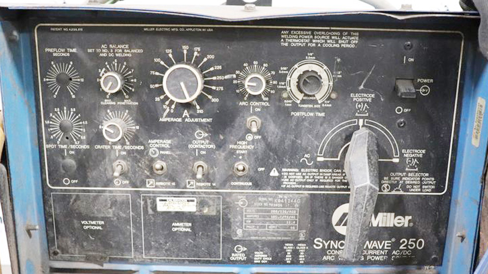
Image by theequipmenthub
Last updated: July 19, 2026
Key Takeaways
- Use DC TIG with electrode negative for normal stainless steel GTAW.
- Start with 100% argon, 15–20 CFH, and the lowest flow that still gives clean coverage.
- Use 2% ceriated or 2% lanthanated tungsten with a clean, lengthwise-ground point.
- Set the machine’s maximum amperage from the material thickness, then use the pedal or hand control to manage actual heat.
- Back purge full-penetration stainless pipe, tubing, and critical joints to prevent backside oxidation or “sugaring.”
At a Glance
| Time Required | About 10–20 minutes for cleaning, machine setup, and a scrap test, plus welding time |
| Difficulty | Intermediate; thin sheet, sanitary tubing, and coded work require more practice |
| Tools Needed | DC-capable Miller TIG welder, TIG torch, remote control if available, argon flowmeter, tungsten grinder, dedicated stainless brush, clamps, and PPE |
| Cost | Varies with argon use, filler rod, tungsten, torch consumables, and purge requirements |
Warning: Stainless welding fume can contain hazardous hexavalent chromium. Use effective local exhaust ventilation, keep your head out of the plume, and follow the respiratory protection rules for your workplace. Argon can also displace oxygen in enclosed spaces.
Why Stainless Steel TIG Welding Needs Different Settings
Stainless steel does not move heat away from the arc as quickly as carbon steel. Heat stays concentrated near the weld, so the joint can distort, overheat, or develop a wide heat-affected zone. Thin stainless is especially easy to burn through.
TIG, also called gas tungsten arc welding or GTAW, gives you close control over the puddle and heat input. That makes it a strong choice for stainless sheet, tubing, exhaust work, food equipment, and visible fabrication. The control still depends on a clean joint, a short arc, steady gas coverage, and the right machine setup.
AWS D1.6/D1.6M:2017-AMD1 remains the listed AWS structural welding code for stainless steel assemblies. It does not automatically govern every stainless job. Pressure, sanitary, marine, repair, and customer-controlled work may require a different code or a qualified WPS. Check the job requirements before treating a settings chart as an approved procedure.
Miller TIG Welder Settings Chart for Stainless Steel
Use this chart as a starting point for flat-position welds on common austenitic stainless such as 304 or 316. The amperage column is the maximum range you set on the machine. With a foot pedal or fingertip control, your actual welding current will often be lower.
| Stainless Thickness | Maximum Amperage Start | Tungsten | Filler Rod | Torch Gas | Pulse Starting Point | Polarity |
|---|---|---|---|---|---|---|
| 0.8–1.0 mm (0.030–0.040 in.) | 25–50 A | 1.6 mm (1/16 in.) | Autogenous with perfect fit-up, or 1.0–1.6 mm | 15–20 CFH (7–9.5 L/min) | Steady DC, 1–2 PPS for rhythm, or higher-speed pulse after a scrap test | DCEN |
| 1.5–2.0 mm (0.060–0.080 in.) | 50–80 A | 1.6 mm (1/16 in.) | 1.6 mm | 15–20 CFH (7–9.5 L/min) | Optional; start at 1–2 PPS, 30% background, 50% peak time | DCEN |
| 3.0–4.0 mm (0.120–0.160 in.) | 80–130 A | 2.4 mm (3/32 in.) | 1.6–2.4 mm | 15–20 CFH (7–9.5 L/min) | Usually steady DC; pulse is optional for heat or bead control | DCEN |
| 5.0–6.0 mm (0.200–0.240 in.) | 130–200 A | 2.4 or 3.2 mm, based on current and duty cycle | 2.4 mm | 15–20 CFH (7–9.5 L/min), then verify coverage | Usually steady DC; use a qualified multi-pass procedure when required | DCEN |
Note: Joint type changes the amperage you need. An outside corner, lap joint, fillet, open root, and autogenous tube joint will not behave the same at one thickness. Test on matching scrap and inspect fusion before welding the finished part.
Understanding the Controls on Your Miller TIG Welder
Miller Dynasty, Maxstar, Syncrowave, and multiprocess machines do not all use the same menu or offer the same pulse range. Use the labels below as a guide, then confirm the control names and limits in your model’s owner’s manual.
Mode and Polarity
Select DC TIG and DCEN, also called electrode negative or straight polarity. This is the normal GTAW setup for stainless steel. AC balance and AC frequency controls are for AC welding, mainly aluminum and magnesium, so they do not tune a normal DC stainless weld.
Maximum Amperage and Remote Control
When you use a foot pedal or fingertip amperage control, the value on the machine is the ceiling, not the current you must hold for the full weld. Set enough maximum amperage to start the puddle without waiting, then ease off as the part becomes hot. Waiting too long for a puddle can add more total heat than using a slightly higher ceiling with faster travel.
Without a remote, set a conservative current and use the machine’s upslope, downslope, and final-current controls if available. Downslope and final current help close the crater without leaving a pinhole or crater crack.
Arc Start, Pre-Flow, and Post-Flow
Use high-frequency start when your machine and work area allow it. HF start keeps the tungsten from touching the work and reduces contamination. Lift-Arc can still work where high frequency is restricted, but you must use a clean, controlled touch.
Miller recommends at least 0.2 second of pre-flow. For post-flow, a useful Miller rule is welding amperage divided by 10, with a minimum of 8 seconds. Keep the torch over the end of the weld until the post-flow stops so the hot tungsten and cooling weld remain shielded.
Pulse Frequency, Background Current, and Peak Time
Pulse is optional. Steady DC is often the easiest setup for plate, short welds, and practice. Pulse can help you time filler additions, narrow the arc, reduce average heat, and control distortion on thin material.
- Low-speed pulse: Start near 1–2 pulses per second when you want a clear rhythm for moving and adding filler.
- Background current: Start around 20–40% of peak. Raise it if the puddle freezes too much between pulses.
- Peak time: Start around 40–60%. Increase it if fusion is weak; reduce it if the puddle grows too wide.
- High-speed pulse: Try 30–100 PPS on matching scrap when you want a tighter, more focused arc. Some Miller inverters can pulse much faster, but more speed is not automatically better.
In one Miller test on 22-gauge 304 stainless, a 175 PPS setup used 40 amps peak, 20% background current, and 75% peak time. The pulsed sample took 30 seconds compared with 45 seconds for straight TIG. Treat that as a case study, not a universal preset.
Choosing Tungsten, Cup, and Shielding Gas
Products Worth Considering

TOP QUALITY: This 10-pack of 2% Lanthanated tungsten electrodes 3/32"x7"(Blue, WL20/EWLa-2) adhere to Standard AWS A5.12M/A5.12:2009 and DIN EN 26848 GB/T 31908-201. All our tungsten has 100% traceability.

TOP QUALITY: This 10-pack of red tig tungsten electrodes 1/16"x7"(Red, WL20/EWLa-2) adhere to Standard AWS A5.12M/A5.12:2009 and DIN EN 26848 GB/T 31908-201. All our tungsten has 100% traceability.

TOP QUALITY: This 10-pack of red tig tungsten electrodes 3/32"x7"(Red, WL20/EWLa-2) adhere to Standard AWS A5.12M/A5.12:2009 and DIN EN 26848 GB/T 31908-201. All our tungsten has 100% traceability.
Best Tungsten for Stainless Steel
For DC stainless, 2% ceriated tungsten with a gray band and 2% lanthanated tungsten with a blue band are dependable choices. Miller recommends both for modern TIG work and notes that pure green tungsten can give poor starting performance on inverter machines.
- 1.6 mm (1/16 in.): A practical choice for thin stainless and lower-current work.
- 2.4 mm (3/32 in.): A strong general-purpose size. Miller lists 3/32-inch tungsten for general TIG work up to about 220 amps.
- 3.2 mm (1/8 in.): Consider it for higher current or long duty cycles, but check the machine and tungsten manufacturer’s chart.
Grind the tungsten lengthwise, not around its circumference. Use a dedicated grinder so steel, aluminum, or abrasive contamination does not enter the electrode. Make a clean point with a small flat at the tip for higher current. A balled end is not the normal preparation for DC stainless.
Pro Tip: If the arc starts wandering, shorten the arc first. Then inspect the tungsten. A contaminated, split, or poorly ground tip can make a good machine feel unstable.
Cup Size, Gas Lens, and Tungsten Stickout
A #8 cup with 3/32-inch tungsten is a useful general setup. A gas lens produces smoother gas flow and lets you use more stickout when access is tight. With a standard collet body, keep the tungsten extension within the cup’s inside diameter. Use the largest practical cup that still gives you access to the joint.
Keep the arc short, usually about 1/16 to 1/8 inch from the work. A long arc spreads heat, widens the puddle, and weakens gas coverage.
Shielding Gas and Flow Rate
Use 100% argon for most stainless TIG welding. Argon/helium blends can produce a hotter arc for special applications, but Miller notes that common blends may contain 25–75% helium. Use a blend only when the procedure, material thickness, and productivity needs justify it.
According to Miller TIG troubleshooting guidance, start around 15–20 CFH (7–9.5 L/min). More flow is not always safer. Excessive gas speed can become turbulent and pull room air into the shielding column. Use the lowest effective flow that keeps the weld and tungsten clean.
Do not solve a draft by turning the regulator far above normal. Block the airflow, move the work, or add a suitable screen without trapping fumes. TIG welding outdoors is difficult because even light wind can strip away the argon shield.
Filler Rod Selection for Stainless Steel
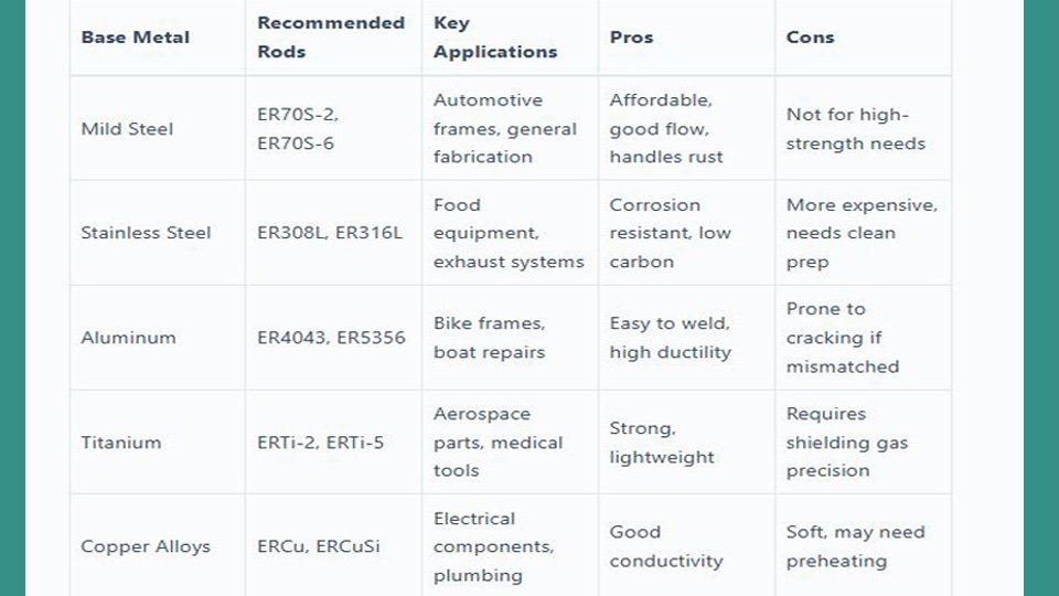
Match the filler to the base metal and the service environment. AWS A5.9/A5.9M:2022 covers bare stainless electrodes and rods used for GTAW and other processes.
- ER308L: Common for 304 and 304L stainless.
- ER316L: Common for 316 and 316L stainless where the added corrosion resistance is required.
- ER309L: Common for joining stainless to carbon steel and for some dissimilar-metal work.
- Other alloys: Stabilized, duplex, high-temperature, or unknown stainless may require a different filler. Confirm the grade and WPS instead of guessing.
Use a rod small enough to melt without chilling the puddle. For 1–2 mm sheet, 1.0–1.6 mm rod is easier to control than a heavy rod. For 3–6 mm material, 1.6–2.4 mm rod is a practical range. Keep the filler clean and inside the shielding envelope while you weld.
I once treated 308L as a universal stainless rod and learned why that shortcut can fail. A weld can look sound while the filler chemistry is wrong for the corrosion service. Check both the alloy and the job requirements before you start.
Products Worth Considering

ER316L 1/16" 3/32" 1/8" x 36" Stainless Steel TIG Welding Filler Rod

er308l stainless steel tig welding rods 1 16 x 16 1 6mm tig filler rod thin stainless sheet tubing handrail kitchen equipment low splatter corrosion resistant stainless steel welding wire tig welding accessories gta w argon arc

ER316L 3/32" x 36" Stainless Steel TIG Welding Filler Rod
Joint Preparation and Heat Control
Clean Without Cross-Contamination
Use a dedicated stainless wire brush, clean files, and abrasives that have never touched carbon steel. Remove oil, marker, adhesive, moisture, and shop dirt from the joint and filler rod. Wipe with an approved solvent only in a ventilated area, keep it away from ignition sources, and let it fully evaporate before striking an arc.
Use the Correct Fit-Up and Bevel
Thin autogenous joints need very tight, even fit-up because the arc cannot bridge a changing gap without adding heat or filler. Other joints may require a controlled root opening. Do not make every stainless joint “gap-free.” Use the drawing, WPS, or a tested joint design.
Material around 3 mm and thicker may need a bevel for full penetration, but the bevel angle, root face, and root gap depend on the joint and procedure. A broad 30–45-degree bevel rule is not a substitute for a qualified detail.
Back Purge Full-Penetration Joints
Back purging protects the root side of stainless tube, pipe, and full-penetration joints. Seal the joint area, provide a vent so the volume cannot pressurize, and introduce clean argon at a controlled rate. Continue the purge long enough to protect the hot root during welding and cooling.
For critical sanitary or corrosion-service work, use an oxygen analyzer and follow the WPS purge limit. A bright outside bead does not prove that the root is protected.
Limit Heat Buildup
Use small, balanced tacks, skip around on long sheet-metal seams, and let the part cool between short welds when needed. Keep your travel speed steady and your arc short. Follow the WPS interpass temperature for coded work instead of using a universal temperature limit.
Remove Heat Tint When the Service Requires It
Dark blue, gray, or black heat tint can signal heavy oxidation, but color alone is not a complete acceptance test. Food, pharmaceutical, marine, chemical, and visible work may require mechanical cleaning, pickling, electropolishing, or passivation after welding. Follow the project specification and chemical manufacturer’s safety instructions. ASTM A967/A967M-25 covers chemical passivation treatments for stainless steel parts.
Step-by-Step Miller TIG Setup for 2 mm 304 Stainless
- Confirm the material: Verify that the part is 304 or 304L stainless and check whether a WPS or code controls the job.
- Prepare the joint: Remove contamination with stainless-only tools, set the required gap, clamp the parts, and arrange a purge if the root will be exposed.
- Install the tungsten: Use clean 1.6 mm ceriated or lanthanated tungsten with a lengthwise-ground point.
- Fit the torch: Start with a gas lens and a #7 or #8 cup when access allows. Keep stickout modest until you confirm coverage.
- Select the process: Choose DC TIG, DCEN, and high-frequency start if available.
- Set maximum amperage: Start at 60–80 amps. Use the pedal to bring in only the heat needed to form and carry the puddle.
- Set shielding gas: Use 100% argon at 15–20 CFH. Check the hose, torch, and fittings for leaks.
- Set timing: Use at least 0.2 second pre-flow and about 8 seconds post-flow at this current level.
- Choose filler: Start with 1.6 mm ER308L for a normal 304-to-304 joint unless the WPS calls for something else.
- Choose pulse or steady DC: Begin with steady current. For thin or distortion-sensitive work, test 1–2 PPS, 30% background current, and 50% peak time on scrap.
- Run a scrap test: Match the material, joint, purge, and position. Check penetration, bead width, oxidation, distortion, and crater fill.
- Weld the part: Hold a 10–20-degree travel angle, keep a short arc, add filler at the front of the puddle, and reduce pedal pressure as the part heats up.
- Finish correctly: Hold the torch over the crater through post-flow, inspect both sides, and complete any required cleaning or passivation.
Common Stainless TIG Problems and Fixes
| Problem | Likely Causes | What to Change |
|---|---|---|
| Porosity | Oil, moisture, gas leak, wrong gas, low flow, or excessive turbulent flow | Reclean the joint and filler, check fittings, confirm pure argon, and reset flow near 15–20 CFH |
| Black or gray weld | Poor shielding, long arc, slow travel, excessive heat, or torch moved away before post-flow ended | Shorten the arc, improve coverage, move faster, reduce heat buildup, and hold the torch in place |
| Warping or burn-through | Too much average heat, wide gap, slow travel, or long weld sequence | Lower pedal input, use shorter welds, improve fit-up, add copper backing when suitable, or test pulse |
| Lack of fusion | Maximum amperage too low, travel too fast, oversized filler, poor joint access, or arc on filler instead of base metal | Raise the current ceiling, pause on the joint faces, use smaller filler, or correct the bevel and torch angle |
| Arc wander | Contaminated or split tungsten, long arc, poor grind, loose work connection, or wrong polarity | Regrind lengthwise, shorten the arc, tighten connections, and confirm DCEN |
| Tungsten burns back | DCEP selected, tungsten too small, poor gas coverage, or not enough post-flow | Select DCEN, increase tungsten size, correct the gas system, and extend post-flow |
| Sugared root | Missing, weak, or contaminated back purge | Improve sealing, add a vent, purge before welding, verify oxygen when required, and maintain purge through the hot root |
| Crater pinhole or crack | Arc stopped too quickly or crater left underfilled | Use downslope or pedal control, add a final filler dab, and let the puddle close before stopping |
Pros and Cons of TIG Welding Stainless with a Miller
Advantages
- Precise heat control: A remote amperage control helps you react as the part heats up.
- Clean process: TIG produces no flux slag and can make neat, low-spatter welds.
- Pulse options: Equipped Miller inverters offer low- and high-speed pulse for thin or distortion-sensitive work.
- Flexible equipment: Depending on the model, one machine can cover stainless, carbon steel, aluminum, and specialty alloys.
Limitations
- Skill requirement: Torch angle, arc length, pedal control, and filler timing take practice.
- Slower deposition: Manual TIG is often slower than MIG or other production processes.
- Gas sensitivity: Drafts and leaks can ruin a weld quickly.
- Model differences: Pulse range, memory, waveform controls, and remote options vary, so one button sequence does not fit every Miller welder.
Safety Considerations for TIG Welding Stainless Steel
OSHA identifies welding on stainless steel as a major source of occupational exposure to hexavalent chromium, which can harm the respiratory system and cause cancer.
OSHA’s permissible exposure limit for hexavalent chromium is 5 micrograms per cubic meter as an 8-hour time-weighted average. Ventilation and exposure controls must match the actual workplace hazard.
- Ventilation: Use local exhaust close enough to capture the plume without pulling away the shielding gas. General room airflow alone may not control exposure.
- Respiratory protection: A respirator may be required when engineering and work-practice controls do not reduce exposure enough. Workplace respirator use requires proper selection, medical evaluation, fit testing, and a respiratory protection program.
- Eye protection: Choose the shade by amperage. OSHA lists a minimum shade 8 below 150 amps and shade 10 above 150 amps for GTAW. ANSI and AWS recommendations shown in OSHA guidance are darker: shade 10 below 50 amps, shade 12 from 50–150 amps, and shade 14 from 150–500 amps.
- Skin protection: Wear flame-resistant gloves, sleeves, and clothing that cover exposed skin from UV radiation and hot metal.
- Fire prevention: Remove flammables, control solvent vapors, and keep suitable fire-extinguishing equipment nearby.
- Electrical safety: Inspect the torch, leads, work clamp, insulation, and connections. Keep gloves and the work area dry.
- Compressed gas safety: Secure cylinders upright, protect the valve, use the correct regulator, and check connections for leaks.
- Confined spaces: Do not rely on argon as “safe air.” It can displace oxygen. Follow confined-space testing, ventilation, attendant, and rescue requirements.
Real-World Applications
- Food and beverage: Tanks, frames, and tubing may need controlled purge quality, smooth roots, and documented cleaning.
- Automotive: Exhausts and turbo plumbing need low distortion, clean fit-up, and often back purging.
- Marine: Filler selection and post-weld surface condition matter because the weld faces a corrosive environment.
- Architectural fabrication: Visible welds need consistent heat input and careful finishing.
- Pressure and process work: Settings must follow the qualified WPS, joint detail, inspection plan, and applicable code.
A 1 mm exhaust joint may run near 35–50 amps with pulse or careful pedal control. A 4 mm plate joint may need roughly 90–130 amps, a larger tungsten, a bevel, and more than one pass. The chart gets you close, but the joint design and inspection requirements decide the final setup.
Conclusion: Start Conservative and Record What Works
For most stainless jobs, start with DCEN, clean ceriated or lanthanated tungsten, 100% argon near 15–20 CFH, and a matching filler rod. Set enough maximum amperage to form the puddle quickly, then control actual heat with the pedal. Add pulse, a gas lens, or back purging only when they solve a real joint problem.
Test on matching scrap, inspect both sides of the weld, and write down the settings that worked. If your Miller has program memory, save the complete setup, including cup, tungsten, gas flow, pulse values, filler, joint type, and purge method. Those details make the preset useful when you return to the job.
Frequently Asked Questions
What is the best tungsten for TIG welding stainless steel on a Miller welder?
Use 2% ceriated (gray) or 2% lanthanated (blue) tungsten for normal DCEN stainless welding. Use a clean point ground lengthwise. A 1/16-inch electrode suits thin, lower-current work, while 3/32 inch is a strong general-purpose size.
How do I prevent warping when welding thin stainless steel?
Use tight, even fit-up, small balanced tacks, a short arc, fast steady travel, and controlled pedal input. Skip around on long seams and let the part cool between short welds. Pulse and suitable copper backing can help, but test them on matching scrap first.
What shielding gas and flow should I use for stainless TIG?
Use 100% argon for most work. Start at 15–20 CFH, or about 7–9.5 L/min, and use the lowest flow that gives clean coverage. Do not keep raising the flow to fight a draft because excessive flow can create turbulence and pull air into the shield.
Should I use pulse or steady current on stainless steel?
Start with steady DC when learning or welding thicker material. Try 1–2 PPS when you want a clear hand rhythm. Test higher-speed pulse on thin sheet when you need a narrower arc or lower average heat. The best values depend on your Miller model and joint.
Why are my stainless TIG welds porous or black?
Check for oil, moisture, gas leaks, the wrong gas, drafts, a long arc, and excessive heat. Confirm DCEN and 100% argon, reset flow near 15–20 CFH, clean the joint and filler, and hold the torch over the crater until post-flow ends.
Do I need to back purge stainless steel?
Back purge full-penetration tube, pipe, sanitary, and critical corrosion-service joints when the root side must remain clean. Seal the purge area, include a vent, introduce argon at a controlled rate, and follow the WPS oxygen limit when one applies.
Can I TIG weld stainless without filler rod?
Yes. Thin stainless can be fusion welded when the joint has precise, even fit-up and the design permits an autogenous weld. Use filler when the joint needs reinforcement, gap control, alloy adjustment, or a procedure that requires added metal.
Which filler rod should I use for 304, 316, or stainless-to-mild-steel joints?
ER308L is common for 304/304L, ER316L for 316/316L, and ER309L for many stainless-to-carbon-steel joints. Service temperature, corrosion conditions, dilution, code rules, and the WPS can change the correct choice.
Sources
- Miller: Guide to TIG Welding Basics: tungsten selection, DCEN, gas flow, arc length, and post-flow guidance
- Miller: Proper Shielding Gas in TIG Welding: argon, gas lenses, pre-flow, post-flow, and turbulence control
- Miller: Pulsed TIG for Stainless Steel: pulse behavior and the 22-gauge stainless case study
- OSHA: Controlling Hazardous Fume and Gases During Welding: hexavalent chromium, ventilation, and respiratory hazards
- OSHA: Eye Protection During Welding and Cutting: GTAW minimum and recommended lens shades by amperage
- AWS D1.6/D1.6M:2017-AMD1, AWS A5.9/A5.9M:2022, and ASTM A967/A967M-25: structural code scope, filler classification, and stainless passivation




[…] New to process selection? Compare methods in MIG vs TIG and see stainless setup in Miller TIG settings for stainless. […]