Getting the right amps for TIG welding stainless steel is a balancing act. Too little current can leave a cold, sluggish puddle or incomplete fusion. Too much heat can cause burn-through, distortion, heavy heat tint, or loss of corrosion resistance. A useful TIG amp chart for stainless steel gives you a safe starting range, but it cannot replace a test weld.
Your final setting also depends on the measured metal thickness, joint type, welding position, fit-up, filler rod, tungsten size, shielding gas, torch angle, travel speed, and whether you use a foot pedal or pulse mode. Treat the chart below as a setup guide for clean 304 or 316 austenitic stainless, then fine-tune the current on matching scrap.
Quick Answer
For stainless TIG, set the machine to DCEN and use roughly 30–50 amps for 0.040-inch sheet, 45–70 amps for 16-gauge sheet, 50–75 amps for 1/16 inch, 90–130 amps for 1/8 inch, and 160–220 amps for 1/4 inch. Test the joint on scrap before welding the part.
Key Takeaways
- Use DCEN for conventional TIG welding of 304, 304L, 316, and 316L stainless steel.
- Measure the material with calipers instead of trusting a gauge label; gauge thickness varies by metal and convention.
- The amperage on the machine is normally a maximum setting. A foot pedal or fingertip control lets you use less current as heat builds.
- Fillet and lap joints often need more current than tight butt joints, while vertical work and open roots often need less.
- Use ER308L for many 304 joints, ER316L for matching 316, and ER309L for many stainless-to-carbon-steel joints.
- Back purge full-penetration roots when the back of the weld must remain oxidation-free and corrosion resistant.
At a Glance
| Time Required | About 15–30 minutes for setup and scrap testing, plus welding and cooling time |
| Difficulty | Intermediate; thin sheet and full-penetration pipe roots require more practice |
| Tools Needed | DC TIG welder, torch, argon regulator and flowmeter, work clamp, tungsten grinder, stainless brush, filler rod, calipers, PPE, and scrap metal |
| Cost | About $10–$30 in filler, tungsten wear, solvent, and argon for a small practice job; welder and cylinder costs are not included |
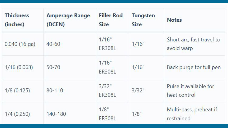
TIG Amp Chart for Stainless Steel by Thickness
The table below gives practical starting ranges for manual TIG welding of clean 304, 304L, 316, or 316L stainless steel. It assumes DCEN polarity, 100% argon, a flat-position joint, a short arc, and reasonably tight fit-up. The listed amperage is the maximum machine setting. Your actual current may be lower when you use a foot pedal, fingertip control, or pulse mode.
Note: Gauge numbers are only approximate and vary by material standard. Measure the work with calipers and select amperage from the actual decimal or metric thickness.
| Measured Thickness | Starting Amps, DCEN | Typical Filler Diameter | Tungsten Diameter | Setup Notes |
|---|---|---|---|---|
| 0.020 in. / 0.5 mm | 10–25 A | Autogenous or 0.035 in. | 0.040 or 1/16 in. | Exact fit-up, tiny arc, and rapid current control are essential. |
| 0.030 in. / 0.8 mm | 20–35 A | 0.035–0.045 in. | 0.040 or 1/16 in. | Use small, closely spaced tacks and avoid gaps. |
| 0.040 in. / 1.0 mm | 30–50 A | 0.035–0.045 in. | 1/16 in. | Copper backing can help control burn-through on accessible joints. |
| 0.048–0.050 in. / about 1.2–1.3 mm | 35–60 A | 0.045 or 1/16 in. | 1/16 in. | Often sold near 18-gauge thickness, depending on the gauge system. |
| 0.060–0.063 in. / about 1.5–1.6 mm | 45–75 A | 0.045 or 1/16 in. | 1/16 in. | This range covers common 16-gauge references and 1/16-inch sheet. |
| 0.075–0.083 in. / about 1.9–2.1 mm | 65–95 A | 1/16 in. | 1/16 or 3/32 in. | A fillet joint may need the upper half of the range. |
| 1/8 in. / 3.2 mm | 90–130 A | 1/16 or 3/32 in. | 3/32 in. | Use the lower end for open roots or vertical work and more current for larger fillets. |
| 3/16 in. / 4.8 mm | 130–180 A | 3/32 in. | 3/32 or 1/8 in. | Bevel groove welds as required and control interpass temperature. |
| 1/4 in. / 6.4 mm | 160–220 A | 3/32 or 1/8 in. | 1/8 in. for sustained high current | A groove and multiple passes are normally more practical than one oversized pass. |
These are setup ranges, not procedure-qualified values. For structural, pressure, sanitary, aerospace, or other code-controlled work, use the approved welding procedure specification rather than a general internet chart.
Pro Tip: Set enough maximum amperage to form the puddle quickly, then control the actual heat with the pedal. Holding a low current for too long can put more total heat into thin stainless than a short, controlled burst at a higher maximum setting.
Understanding TIG Amperage Settings for Stainless Steel
TIG welding stainless steel requires careful heat control. Austenitic stainless transfers heat more slowly than carbon steel, so heat remains concentrated near the weld and builds as you travel. That makes later portions of a long seam more likely to sag, discolor, or distort unless you reduce pedal pressure or pause to cool.
The old “one amp per 0.001 inch” rule can help you estimate a machine’s maximum setting, but it is not a finished welding procedure. A 0.125-inch plate may put you near 125 amps, yet a tight autogenous butt joint might use less while a large fillet joining two heavy parts may need more.
Do not automatically reduce every stainless setting by a fixed percentage. Instead, start within the chart range and adjust based on the puddle. You need enough current to wet both joint faces without holding the arc in one place.
How Joint Type and Position Change the Amps
| Condition | Likely Adjustment | Reason |
|---|---|---|
| Tight autogenous butt joint | Use the lower half of the range | There is little filler to melt and less metal mass around the arc. |
| Filler-added butt joint | Use the middle of the range | The filler rod cools the puddle each time it is added. |
| Fillet or lap joint | Often 10%–20% more than a tight butt-joint starting point | The arc must heat more surrounding metal and fuse into a corner. |
| Vertical or overhead joint | Often 5%–15% less | A smaller puddle is easier to control against gravity. |
| Open-root joint | Begin near the low end and use precise current control | The exposed root edge is easy to overheat or collapse. |
| Copper chill bar or heavy fixture | May require slightly more maximum current | The fixture draws heat away from the joint. |
| Poor fit-up or a wide gap | Do not simply increase current | Correct the fit-up, use smaller filler, or bridge the gap with controlled tacks. |
How to Read a TIG Amp Chart for Stainless Steel
Read the thickness column first, but confirm the measurement with calipers. Next, check the joint geometry, welding position, filler size, and required penetration. The same 1/16-inch sheet may weld near 50 amps in a tight butt joint and closer to 70 amps in a fillet joint.
The chart’s amperage is best treated as the top of your usable control range. Setting a pedal-equipped machine to 70 amps does not mean you must weld continuously at 70 amps. You may use most of that output to start the puddle, then back off as the panel warms.
Also check the welder and torch duty-cycle ratings. A small air-cooled torch that handles short 120-amp welds may overheat during a long multi-pass joint at the same current. Do not exceed the ratings in the equipment manuals.
Charts also cannot account for cast-to-cast differences, exact joint restraint, surface condition, gas coverage, or the skill of the operator. Write down the successful settings from your scrap tests so you can repeat them on later jobs.
Selecting Filler Rods for TIG Welding Stainless Steel
Filler metal must support the required strength, corrosion resistance, temperature exposure, and service environment. The current AWS A5.9/A5.9M:2022 specification classifies bare stainless welding electrodes and rods by chemical composition.
| Base Metal or Joint | Common Filler Starting Point | Important Note |
|---|---|---|
| 304 or 304L to itself | ER308L | A common general-purpose match for 304-series base metal. |
| 316 or 316L to itself | ER316L | Contains molybdenum for improved pitting resistance in suitable service. |
| Stainless to carbon or low-alloy steel | ER309L | Common for dissimilar joints, but suitability still depends on dilution and service conditions. |
| 321 or 347 stainless | ER347 | Often selected for stabilized stainless grades and elevated-temperature service. |
| 2205 duplex stainless | ER2209 when specified | Duplex requires controlled heat input, interpass temperature, filler, and shielding under an approved procedure. |
| Unknown stainless grade | Identify the alloy before welding | Appearance and magnet response are not enough to select filler reliably. |
For thin sheet, a 0.035-, 0.045-, or 1/16-inch filler is easier to melt without chilling the puddle. Use 3/32-inch filler as the joint and current increase. A rod that is too large can force you to dwell on the joint, while a rod that is too small may require excessive feeding.
Keep the rod clean and inside the shielding envelope near the puddle. Do not allow its hot end to oxidize outside the gas and then dip that oxidized tip back into the weld. Store filler in a clean, dry container and keep carbon-steel grinding dust away from it.
Products Worth Considering

ER308L TIG WELDING ROD: ER308L is a low -carbon stainless steel tig welding rod, which has excellent anti -crystal interval corrosion properties and full -location welding performance.

er308l stainless steel tig welding rods 1 16 x 16 1 6mm tig filler rod thin stainless sheet tubing handrail kitchen equipment low splatter corrosion resistant stainless steel welding wire tig welding accessories gta w argon arc

Premium Material: Crafted from high-grade stainless steel, ER308L rods ensure superior strength & durability for professional welding work
Machine Settings and Equipment for Stainless Steel TIG
A DC-only TIG welder is sufficient for conventional stainless welding. Miller’s TIG welding guide identifies DCEN as the normal polarity for steel and stainless steel.
| Setting | Practical Starting Point | What to Watch |
|---|---|---|
| Polarity | DCEN | Do not apply an AC balance setting to a conventional DCEN weld. |
| Shielding gas | 100% argon | Specialized procedures may use other blends, but argon is the normal manual TIG starting gas. |
| Torch flow | About 12–20 CFH with a standard setup; often 8–15 CFH with a suitable gas lens | Cup size, tungsten stickout, drafts, joint shape, and equipment affect the correct flow. |
| Pre-flow | About 0.5–1 second | Use enough time to clear air from the torch before arc initiation. |
| Post-flow | About 1 second per 10 amps as a starting rule | Increase it if the hot tungsten oxidizes; follow the machine manual. |
| Arc start | High-frequency non-contact start when available | Touch starts can contaminate the tungsten or work if technique is poor. |
| Cup | Commonly #5–#8; larger when extra coverage or stickout is needed | A larger cup may require different flow and better access around the joint. |
| Arc length | About 1/16–1/8 inch | A long arc raises voltage, spreads heat, and weakens shielding coverage. |
Products Worth Considering

Includes jumbo alumina ceramic cups (53N87, 53N88), pure copper collet bodies, and back caps. Designed for WP-17/18/26 TIG torches. Each part in labeled slot with part number for easy identification

Set includes:3pcs Back cup, 20 collets, 8pcs collet body, 25pcs Alumina gas cup/ nozzle, 2 gasket

Comes with 1 full cup, spare gas lens diffuser, and o-rings for mounting
Optional Pulse Settings
Pulse TIG is useful for controlling puddle size and reducing average heat input, but it is not required for every stainless weld. A simple manual starting point is:
- Peak current: Set within the thickness chart range.
- Background current: Start around 25%–40% of peak current.
- Peak time: Start around 30%–50% of the pulse cycle.
- Pulse frequency: Try 1–2 pulses per second when you want a visible rhythm for adding filler.
Higher pulse frequencies can create a smoother-looking arc and tighter puddle, but the useful setting varies greatly by machine and joint. Change one pulse control at a time and compare the result on scrap. Miller explains the relationship between peak current, background current, and pulse frequency in its pulse TIG guide.
Choosing and Preparing the Tungsten
For general DC stainless TIG, 2% lanthanated or 2% ceriated tungsten provides reliable starting and arc stability. Modern guidance commonly recommends these options instead of treating thoriated tungsten as the automatic choice.
| Tungsten Diameter | Useful DC Range | Typical Use |
|---|---|---|
| 0.040 in. / 1.0 mm | Low-current work, commonly below about 70 amps | Foil, very thin sheet, and tiny precision joints |
| 1/16 in. / 1.6 mm | Commonly up to about 100–150 amps, depending on tungsten type and tip | Thin sheet through light plate |
| 3/32 in. / 2.4 mm | Broad general-purpose range, including work above 150 amps | 1/8-inch plate, fillets, and general fabrication |
| 1/8 in. / 3.2 mm | High-current or sustained welding | Thick plate and multi-pass work |
The CK Worldwide TIG technical guide provides detailed current ranges by electrode diameter, tip diameter, and point angle. Grind the tungsten lengthwise on a wheel used only for tungsten. A pointed tip with a small flat at the end gives a focused DC arc and reduces the risk of the point breaking into the puddle.
If the tungsten touches the puddle or filler rod, stop and regrind it. Continuing with a contaminated electrode can cause arc wander, inclusions, porosity, and an unstable bead.
Joint Preparation for TIG Welding Stainless Steel
Cleanliness is critical. Remove oil, paint, marker residue, moisture, adhesive, scale, and embedded carbon-steel particles from both sides of the joint. Use a clean lint-free cloth, an approved solvent, and a brush reserved for stainless steel.
Warning: Never weld on metal that is wet with solvent or near chlorinated solvent vapors. Some chlorinated cleaners can form highly toxic gases when exposed to welding heat or ultraviolet radiation. Remove the cleaner, move the container away, and let the work dry completely.
- Measure the material. Use calipers instead of assuming the sheet gauge.
- Identify the alloy. Confirm whether the material is 304, 316, duplex, ferritic, martensitic, or another grade.
- Remove contamination. Clean the base metal and filler rod without using carbon-steel brushes or contaminated abrasives.
- Correct the fit-up. Thin butt joints should have a tight, even gap unless a qualified procedure specifies otherwise.
- Prepare the groove when needed. Thick full-penetration joints may need a V- or U-groove, root face, and root opening defined by the drawing or WPS.
- Clamp and tack evenly. Use enough short tacks to hold alignment while allowing for shrinkage.
Do not apply one groove angle or root opening to every joint. A pressure pipe root, structural groove weld, sanitary tube weld, and decorative sheet-metal seam may require completely different preparation.
Step-by-Step Guide to TIG Welding Stainless Steel
- Set up the work area. Remove combustibles, secure the argon cylinder upright, provide local exhaust ventilation, and place screens where other people could be exposed to the arc.
- Connect and inspect the equipment. Select DCEN, attach the work clamp to clean metal, inspect torch insulation and hoses, install the correct collet and cup, and leak-check the shielding-gas path.
- Prepare the tungsten and filler. Grind a clean lanthanated or ceriated tungsten lengthwise, add a small flat to the point, and wipe the correct filler rod clean.
- Set gas and amperage. Begin with 100% argon near 12–20 CFH for a standard torch setup, choose the chart range for the measured thickness, and set suitable pre-flow and post-flow.
- Make a scrap test. Reproduce the same thickness, joint, filler, position, backing, and purge conditions. Check puddle response, penetration, bead width, distortion, and backside oxidation.
- Start the arc with a short gap. Hold the torch roughly 10–15 degrees in the travel direction and keep the tungsten about 1/16–1/8 inch from the work.
- Form the puddle promptly. Use enough current to wet both joint faces without lingering. Add filler near the leading edge while keeping the hot rod tip inside the shielding gas.
- Reduce heat as the joint warms. Ease off the pedal, increase travel speed slightly, skip to a cooler area, or pause between sections when the puddle becomes wider or more fluid.
- Finish the crater. Taper the current down while adding enough filler to avoid leaving a deep crater. Keep the torch over the weld until post-flow ends.
- Inspect and clean. Check the face and root for oxidation, porosity, undercut, incomplete fusion, crater cracks, and unacceptable distortion. Remove heat tint when required by the service condition or specification.
When and How to Back Purge Stainless Steel
Back purging protects the root side of a full-penetration weld from oxygen while the metal is molten and hot. Without protection, the root may develop rough black oxidation called sugaring. Miller notes that sugaring can weaken the joint and compromise corrosion resistance.
Back purging is commonly needed for:
- Full-penetration stainless pipe and tube welds
- Sanitary or high-purity process systems
- Corrosion-critical tanks and vessels
- Exhaust tubing when the inside surface must remain smooth
- Joints whose root cannot be cleaned after welding
- Work performed under a WPS that requires root shielding
A cosmetic fillet with no exposed root normally does not need a backside purge. Follow the drawing, procedure, owner specification, or governing code instead of assuming that every stainless joint must be purged.
Basic Purge Setup
- Seal the joint volume with suitable purge dams, tape, plugs, or tooling.
- Provide a small vent at the high point so displaced air can escape.
- Introduce argon at a controlled rate without pressurizing the assembly.
- Allow enough time for the argon to replace the trapped air.
- Keep the purge flowing through the root pass and until the hot root no longer oxidizes.
- Verify purge quality using an oxygen analyzer when the procedure or service requires a measured oxygen limit.
Excessive purge flow can create turbulence, waste gas, or push against the molten root. More flow is not always better.
Controlling Warping, Heat Tint, and Corrosion Resistance
Stainless sheet expands as it heats and contracts as it cools. Long, slow welds concentrate shrinkage in one direction, which can pull a flat panel into a wave or twist a bracket out of alignment.
To limit distortion:
- Keep fit-up tight and tack at even intervals.
- Use the shortest practical arc.
- Travel steadily instead of waiting for an oversized puddle.
- Use skip welding or back-step sequencing on long seams.
- Alternate between separated sections so one area can cool.
- Use copper backing or rigid fixtures when the part allows it.
- Avoid excessive filler and oversized beads.
- Use pulse mode when it improves control without slowing travel excessively.
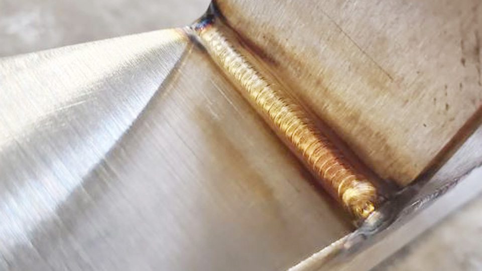
Heat tint is an oxide layer produced beside and on the weld. Dark blue, purple, gray, or black color often points to excessive heat, poor shielding, a long arc, slow travel, or an inadequate purge. Light gold or straw color indicates less oxidation, but it does not automatically prove that a weld meets a corrosion or sanitary specification.
The Nickel Institute explains that heat tint can leave a chromium-depleted layer below the oxide and reduce corrosion resistance. Depending on the service, the finished joint may require stainless brushing, mechanical polishing, pickling, electropolishing, or passivation under an approved procedure.
Common Mistakes in TIG Welding Stainless Steel and Fixes
| Problem | Likely Causes | Practical Fix |
|---|---|---|
| Burn-through | Too much current, wide gap, long arc, slow travel, or poor edge support | Correct the fit-up, shorten the arc, reduce pedal pressure, travel faster, or use copper backing. |
| Incomplete fusion | Current too low, travel too fast, oversized filler, poor torch aim, or dirty joint | Increase usable current, direct the arc at both joint faces, use smaller filler, and clean the joint. |
| Wide bead and heavy color | Long arc, excessive dwell, too much current, poor gas coverage, or accumulated heat | Shorten the arc, increase travel speed, reduce current as the part warms, and verify gas coverage. |
| Black or crusty root | No purge, inadequate purge, trapped air, leak, or excessive root heat | Seal and vent the purge volume, displace the air fully, maintain flow, and reduce root heat if needed. |
| Porosity | Oil, moisture, gas leak, draft, contaminated filler, excessive flow, or dirty tungsten | Clean and dry the joint, inspect hoses and fittings, shield drafts, correct gas flow, and regrind the tungsten. |
| Filler balls instead of flowing | Filler placed outside the puddle, long arc, oxidized rod tip, or puddle too cold | Keep the rod in the gas envelope and dab it into the leading edge of a properly formed puddle. |
| Arc wandering | Contaminated or poorly ground tungsten, long arc, loose connection, or magnetic effects | Regrind lengthwise, shorten the arc, inspect connections, and reposition the work clamp if needed. |
| Crater crack | Arc stopped abruptly with an unfilled crater | Taper the current down and add filler before extinguishing the arc. |
| Rust spots after welding | Embedded carbon-steel particles or contaminated tools | Use dedicated stainless tools and complete the required post-weld cleaning or passivation. |
Safety Considerations for TIG Welding Stainless Steel
Warning: Stainless welding can produce hazardous fumes containing chromium and nickel compounds. Do not rely on odor, visible smoke, an open door, or a household fan to judge whether exposure is safe. Use source-capture ventilation and follow the applicable workplace exposure and respiratory-protection requirements.
OSHA states that chromium in stainless steel can be converted to hexavalent chromium during welding. Cr(VI) can damage the eyes, skin, respiratory system, and internal organs and is known to cause cancer.
OSHA’s permissible exposure limit for hexavalent chromium is 5 micrograms per cubic meter of air as an eight-hour time-weighted average.
Use local exhaust close enough to capture the plume without pulling shielding gas away from the arc. Respiratory protection may also be required when engineering and work-practice controls do not reduce exposure adequately. Workplace respirator use requires proper selection, fit testing, medical evaluation, training, and a written respiratory-protection program.
Argon is not poisonous, but it displaces oxygen. Never weld in a tank, pipe, vessel, pit, or other confined space without the required atmospheric testing, ventilation, entry procedures, attendant, communications, and rescue plan. A welding helmet or respirator does not make an oxygen-deficient atmosphere safe.
- Wear safety glasses under the welding helmet, flame-resistant clothing, dry welding gloves, and suitable footwear.
- Select the lens shade by welding current and the helmet manufacturer’s instructions. OSHA lists minimum GTAW shade 8 below 150 amps and shade 10 from 150–500 amps; a darker shade may be chosen when needed.
- Keep skin covered from ultraviolet and infrared radiation.
- Inspect cables, torch insulation, connectors, and the work clamp before use.
- Keep gloves and clothing dry and avoid direct contact with live electrical parts.
- Secure the gas cylinder upright with a chain or approved restraint and protect the valve from impact.
- Remove flammable materials and keep a suitable fire extinguisher nearby.
- Allow hot stainless to cool in a marked area; it may look identical to cold metal.
See OSHA’s Controlling Hazardous Fume and Gases During Welding fact sheet for additional exposure-control guidance.
Pros and Cons of TIG Welding Stainless Steel
Advantages:
- Precise current and puddle control
- Clean welds with no flux or slag
- Excellent control on thin sheet and tubing
- Suitable for autogenous and filler-added joints
- Strong control over root shape in pipe and sanitary work
- Useful in all welding positions with the correct procedure
Limitations:
- Slower than MIG for many production welds
- Requires clean material and good hand coordination
- Shielding gas is easily disturbed by drafts
- Heat can build quickly in stainless during long seams
- Back purging adds time, tooling, and gas use
- Poor technique can produce attractive-looking welds with incomplete fusion
TIG is often the better choice when appearance, root control, cleanliness, or precision matters. MIG may be more economical when production speed and deposition rate are the main priorities and the approved procedure permits it.
Real-World Applications and U.S. Shop Practices
Stainless TIG is widely used for automotive exhausts, food-processing equipment, brewery piping, pharmaceutical systems, laboratory equipment, architectural fabrication, chemical-service components, and pressure systems. The required procedure depends on the application—not simply on the stainless grade.
AWS D1.6/D1.6M:2017-AMD1 covers stainless steel structural assemblies. It does not mean every stainless project automatically requires the same inspection or nondestructive examination. The contract documents, engineer, code clauses, and approved quality plan establish the requirements.
ASME BPVC Section IX contains rules for qualifying welding procedures and welding personnel when another construction code requires those qualifications. It is not a stand-alone design or fabrication code.
High-purity pharmaceutical and bioprocessing work may also fall under ASME BPE, owner specifications, and project-specific limits for purge quality, weld profile, heat tint, surface finish, and documentation.
For hobby and general fabrication, start within the chart range, test the complete joint on matching scrap, and change one variable at a time. For code work, follow the approved WPS, filler classification, inspection plan, and acceptance criteria. A chart helps you approach the correct setting, but the finished weld must still demonstrate adequate fusion, penetration, shielding, shape, and corrosion performance.
Frequently Asked Questions
What amperage should I use for 1/8-inch stainless steel TIG welding?
Start around 90–130 amps DCEN for clean 304 or 316 stainless in the flat position. A tight butt joint may use the lower half, while a fillet may need the upper half. Set the maximum current, make a scrap test, and control the actual heat with the pedal.
How many amps should I use for 16-gauge stainless steel?
Measure the sheet because gauge conventions vary. Material near 0.060–0.063 inch usually starts around 45–75 amps DCEN. Tight butt joints may weld near the lower end, while fillet or lap joints may need more current.
How do I prevent warping when TIG welding thin stainless steel?
Use tight fit-up, small evenly spaced tacks, a short arc, steady travel, skip-weld sequencing, and the least heat that still produces fusion. Reduce pedal pressure as the panel warms. Copper backing or a rigid fixture can also help when the joint design allows it.
What is the best filler rod for 304 stainless steel?
ER308L is a common filler for welding 304 or 304L stainless to itself. Confirm the exact base metal, service temperature, corrosion exposure, and project specification before selecting filler for critical work.
Do I need to back purge every stainless TIG weld?
No. Back purging is normally used when a full-penetration root or inaccessible backside must remain free of heavy oxidation. A surface fillet with no exposed root may not need it. Follow the drawing, WPS, code, or service requirements.
Can I TIG weld different stainless grades with the same settings?
Not safely as a general rule. Austenitic, ferritic, martensitic, duplex, and precipitation-hardening stainless grades have different filler, heat-input, interpass-temperature, and shielding requirements. Identify both metals and follow an approved procedure for unfamiliar or critical alloys.
What argon flow should I use for stainless TIG?
A standard torch setup often starts around 12–20 CFH. A suitable gas lens may work around 8–15 CFH. Adjust for cup size, tungsten stickout, joint access, drafts, and the torch manufacturer’s guidance. Excessive flow can create turbulence and draw air into the shielding envelope.
Should I use pulse TIG on stainless steel?
Pulse is optional but useful for thin sheet, out-of-position work, and controlling average heat input. Start with the normal peak-current range, background current near 25%–40%, peak time near 30%–50%, and one or two pulses per second. Test and adjust because controls vary by machine.
Sources
- Miller — Guide to TIG Welding Basics — DCEN polarity, tungsten preparation, arc length, gas flow, and general TIG setup
- CK Worldwide — Technical Guide for TIG Welding — tungsten current ranges, cup selection, gas flow, and torch positioning
- OSHA — Controlling Hazardous Fume and Gases During Welding — hexavalent chromium, ventilation, respiratory hazards, and oxygen displacement
- American Welding Society — D1 Committee Standards — scope and current listing for AWS D1.6 structural stainless welding
- AWS A5.9/A5.9M:2022 — classification of bare stainless welding electrodes and TIG rods
- Nickel Institute — Heat Tints on Stainless Steels — corrosion effects of weld heat tint and the need for suitable cleanup