Getting your stick welder settings right can make the difference between a smooth, fused bead and a weld that sticks, spatters, undercuts, or burns through. A useful stick welder settings chart helps you match electrode type, rod diameter, amperage, polarity, metal thickness, and welding position before you strike an arc.
The chart is a starting point, not a substitute for the range printed on the electrode package. Two rods with the same AWS classification can have different recommended settings, and your joint design, machine output, cable condition, travel speed, and position also affect the final setting.
Below, you’ll learn how to choose common electrodes such as E6010, E6011, E6013, and E7018, set up the machine, fine-tune the arc on scrap, and correct common weld problems without guessing.
Quick Answer
Use the electrode maker’s amperage range as your starting point. Match rod type and diameter to the metal, set the required polarity, then test on clean scrap. Many common 1/8-inch E6010, E6011, E6013, and E7018 products run between about 60 and 160 amps, but the package instructions always override a generic chart.
Key Takeaways
- Choose the electrode first. Rod type and diameter determine the usable amperage and polarity.
- Start near the middle of the manufacturer’s range, then adjust in 5- to 10-amp steps on scrap.
- Use a short arc, the correct work angle, and only a small travel angle. A 45-degree travel angle is usually too steep.
- Keep E7018 low-hydrogen electrodes dry exactly as the manufacturer requires. Do not use a household oven or a single drying temperature for every rod.
- For structural, pressure, vehicle-frame, lifting, or other critical work, follow an approved welding procedure and inspection requirements.
At a Glance
| Time Required | About 10 to 20 minutes to select a rod, prepare the joint, set the machine, and test on scrap |
| Difficulty | Beginner to intermediate; out-of-position and code work require more skill |
| Tools Needed | Stick welder, correct electrodes, work clamp, chipping hammer, wire brush or grinder, scrap steel, and full welding PPE |
| Cost | Low if you already own the welder and PPE; the main consumables are electrodes, abrasives, and practice metal |
Stick Welding Basics
Stick welding, also called shielded metal arc welding or SMAW, creates an arc between a flux-coated electrode and the workpiece. The arc melts the base metal and the electrode’s metal core. The coating produces shielding gases and slag that protect the weld as it cools.
Your result depends on five connected controls:
- Electrode classification: Determines tensile-strength class, usable positions, coating type, and current requirements.
- Rod diameter: Larger rods carry more current and deposit more metal, but they need a larger puddle and more machine output.
- Amperage: Controls how easily the rod starts, how fluid the puddle becomes, and how much heat enters the joint.
- Polarity: AC, DCEP, or DCEN can change arc stability, penetration, and whether a particular electrode runs correctly.
- Technique: Arc length, work angle, travel angle, speed, and bead pattern can make a correct machine setting perform well or badly.
Mild steel is a practical material for learning because it is common and works with several general-purpose electrodes. Clean the joint to bright metal when possible. Remove oil, moisture, rust scale, paint, plating, and other coatings that can cause porosity, unstable arcs, toxic fumes, or lack of fusion. I learned early that skipping preparation can turn a promising bead into a weak repair.
Warning: A rod that can penetrate light rust does not make paint, oil, galvanized coating, lead paint, or unknown metal safe to weld. Identify and remove coatings where practical, control fumes, and never weld a used tank, drum, or sealed container unless it has been professionally cleaned, vented, and made safe for hot work.
AC, DCEP, and DCEN Explained
- AC: Alternating current changes direction repeatedly. E6011 and many E6013 and E7018 products can run on AC, which is useful on AC-only machines and can reduce some forms of arc blow.
- DCEP: Direct current electrode positive, sometimes called DC reverse polarity. It is the preferred setting for many E6010 and E7018 products.
- DCEN: Direct current electrode negative, sometimes called DC straight polarity. Some E6011 and E6013 products permit it, and some E6010 products list it as an alternative. Always check the exact electrode package.
Do not confuse the work lead with a protective earth ground. The work clamp completes the welding circuit. Place it on clean metal close to the joint to reduce resistance and arc problems, but still follow the welder manufacturer’s electrical grounding instructions.
Types of Stick Welding Rods and When to Use Them
Common carbon-steel stick electrodes use an AWS classification such as E6010 or E7018. In a four-digit classification, E means electrode, the first two digits show the minimum tensile-strength class in thousands of pounds per square inch, the third digit identifies welding position, and the final digit identifies coating and current characteristics. For example, E7018 is a 70,000 psi-class, all-position, low-hydrogen electrode.
Products Worth Considering

E7018 Welding Rod: Diameter: 3/32''; Length: 14"; Weight: 5 lb.

Product Introduction: E7018 welding rod is suitable for both AC and DC applications and can be used for all position welding

【 AWS-COMPLIANT E7018 LOW-HYDROGEN ELECTRODES 】: Metal Marlin H4R provides premium quality, low-hydrogen, arc welding carbon steel stick electrodes that ensure strong, reliable welds for all projects, ensuring strong and reliable welds with low hydrogen content, conforming to AWS A5.1 E7018 and ASME SFA-5.1 E7018 requirements.
E6010
E6010 produces a forceful, fast-freezing arc with deep penetration. It is common for pipe root passes and field work where an experienced welder needs strong puddle control. It runs on DC, with DCEP preferred for many products. The tight, forceful arc can be difficult for a beginner, and not every small inverter runs E6010 well because the machine may lack suitable open-circuit voltage or arc characteristics.
E6011
E6011 has a fast-freezing, penetrating arc and works on AC or DC when the product permits. It is useful for maintenance and repair, including steel that cannot be cleaned perfectly. Clean the joint as well as you can anyway. Rust-tolerant does not mean contamination-proof.
E6013
E6013 offers an easy-starting, smooth arc, light spatter, and relatively shallow penetration. It works well for clean sheet steel, light fabrication, short welds, and practice beads. It is not the best choice when you need deep root penetration or when the joint has serious contamination or poor preparation.
E7018
E7018 is a low-hydrogen electrode used for many structural and multi-pass carbon-steel welds. It provides a smooth arc, good bead appearance, and a 70,000 psi tensile-strength class. Keep it dry according to the manufacturer’s instructions. For more detail, see this guide to low-hydrogen electrode storage.
Some E7018 products run on DCEP and AC, while others may allow additional current types. The exact package and welding procedure control. For code work, exposure limits, holding temperature, and reconditioning rules may be stricter than a general shop recommendation.
Electrodes for Stainless Steel and Cast Iron
Match the electrode to the actual base metal and service requirement. E308L-16 is commonly used for 304 and 308 stainless steel, while E309L-type electrodes are often selected for stainless-to-carbon-steel joints. Cast iron commonly needs a nickel or nickel-iron electrode and a repair plan that controls heat input and cooling. Do not select either electrode by appearance alone.
Pro Tip: Keep the electrode box or data sheet beside the welder. The printed range for that exact product is more reliable than a universal chart, especially for E7018, stainless, cast-iron, and specialty electrodes.
How to Read and Use a Stick Welder Settings Chart
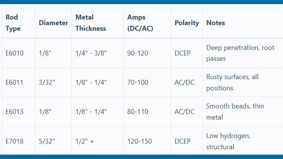
A good settings chart should show the electrode classification, rod diameter, usable polarity, and amperage range. Metal thickness can help you choose a rod diameter, but it does not set amperage by itself. Joint type, root opening, bevel, position, pass number, and heat-sink effect also matter.
The ranges below come from specific Lincoln Electric product sheets for Fleetweld 5P E6010, Fleetweld 180 E6011, Fleetweld 37 E6013, and Excalibur 7018 MR. Other brands can differ, so confirm the package before welding.
| Rod Type | Diameter | DCEP | AC | DCEN | Typical Use |
|---|---|---|---|---|---|
| E6010 | 3/32 in | 40 to 80 A | Not listed | 50 to 85 A* | Root passes, pipe, repair |
| E6010 | 1/8 in | 70 to 130 A | Not listed | 75 to 135 A* | Deep-penetrating root and repair work |
| E6010 | 5/32 in | 90 to 165 A | Not listed | 100 to 175 A* | Higher-deposition pipe and plate work |
| E6011 | 3/32 in | 40 to 80 A | 40 to 90 A | 40 to 80 A | Thin repair work and AC machines |
| E6011 | 1/8 in | 60 to 110 A | 65 to 120 A | 60 to 110 A | General repair and less-than-perfect steel |
| E6011 | 5/32 in | 105 to 135 A | 115 to 150 A | 105 to 135 A | Heavier repair work |
| E6013 | 3/32 in | 70 to 105 A | 75 to 115 A | 70 to 105 A | Clean sheet and light fabrication |
| E6013 | 1/8 in | 100 to 135 A | 110 to 140 A | 100 to 135 A | Smooth beads on clean mild steel |
| E6013 | 5/32 in | 145 to 180 A | 160 to 200 A | 145 to 180 A | Higher-deposition light fabrication |
| E7018 | 3/32 in | 70 to 110 A | 80 to 120 A | Follow package | Small fillets and out-of-position work |
| E7018 | 1/8 in | 90 to 160 A | 100 to 160 A | Follow package | Structural fillets and multi-pass welds |
| E7018 | 5/32 in | 130 to 210 A | 140 to 210 A | Follow package | Heavy plate and higher deposition |
*DCEP is the preferred polarity for the cited E6010 product. Some E6010 data sheets also list DCEN, but you should not assume every E6010 electrode will run well that way.
Products Worth Considering

large 500 amp electrode holder provides durability, 5/8~7/16 inch electrode capacity

Durable Material: ARCCAPTAIN electrode holder is made of high quality copper as well as insulating materials to ensure high efficiency and safety while welding.

Comprehensive Welding Package: our package comes with 24 low temperature universal welding rods available to meet your welding requirements; Whether you are a novice or an experienced welder, this kit of welding rods ensures you have things you need for your welding projects; Material is relatively brittle, received with breakage is a normal phenomenon, does not affect the use
Rod Diameter by Metal Thickness
Use this as a practical shop starting point for mild steel, not as a qualified procedure:
| Steel Thickness | Common Starting Rod Size | What to Watch |
|---|---|---|
| Under 1/8 in | 1/16, 5/64, or 3/32 in when the electrode and machine support it | High burn-through and distortion risk; MIG or TIG is often easier |
| About 1/8 to 3/16 in | 3/32 in | Use tight fit-up, short beads, and a low but stable setting |
| About 3/16 to 3/8 in | 1/8 in | Joint design and bevel become more important as thickness increases |
| About 3/8 in and thicker | 1/8 or 5/32 in | Expect beveling and multiple passes rather than one oversized bead |
How to Fine-Tune the Amperage
- Confirm the electrode classification, diameter, and polarity on the package.
- Start near the middle of the listed range for flat welding on clean scrap of the same thickness.
- Run a short bead using a steady arc length and travel speed.
- If the rod sticks, the arc repeatedly goes out, or the bead sits high with poor tie-in, increase current by 5 to 10 amps.
- If the puddle becomes hard to control, the rod overheats, spatter rises sharply, or the bead undercuts the toes, reduce current by 5 to 10 amps.
- For overhead or vertical work, begin in the lower part of the product’s range. A reduction near 10 to 15 percent from a good flat setting is a common starting point, but the product sheet or WPS controls.
The correct number is the setting that gives stable starts, a controllable puddle, full tie-in, and the required bead profile on your actual joint. The chart gets you close; the test bead confirms it.
Note: Inverter displays and old transformer dials may not deliver exactly the number shown. Long, undersized, damaged, or loosely connected cables can also change arc performance. Record the machine, lead setup, rod brand, polarity, and successful setting for repeat jobs.
Step-by-Step Guide to Setting Up Your Stick Welder
Use this setup sequence before every new combination of material, electrode, or position.
- Identify the base metal and job requirement. Confirm whether the part is mild steel, high-strength steel, stainless, cast iron, or another alloy. Critical work may require a WPS, preheat, specific filler metal, and inspection.
- Select the electrode. Use E7018 for many clean structural applications, E6011 for many AC repair jobs, E6010 for suitable DC root and field work, and E6013 for clean light fabrication.
- Inspect the welder and leads. Look for damaged insulation, loose lugs, overheated connectors, a worn holder, and a weak work clamp. Do not use damaged equipment.
- Set the current type and polarity. Connect the holder and work lead exactly as the electrode data sheet and welder manual require. Turn the machine off before moving output connections.
- Check electrode condition. Reject rods with cracked, flaking, contaminated, or badly damaged coating. Keep low-hydrogen rods in approved storage after opening.
- Prepare the joint. Remove contamination and create the root face, root opening, bevel, and fit-up required for the joint. Thick plate usually needs a groove and multiple passes.
- Attach the work clamp. Clamp to clean metal near the weld, not over paint, rust, a bearing, or a path that sends current through sensitive components.
- Set the starting amperage. Use the package range and begin near the middle for flat work. Move toward the lower end for thin metal or out-of-position welding.
- Prepare the work area and PPE. Remove combustibles, provide ventilation, set screens, and wear safety glasses under the helmet, dry welding gloves, flame-resistant clothing, and suitable footwear.
- Test on scrap. Use the same material thickness, joint orientation, and electrode. Adjust by 5 to 10 amps until starts and puddle control are stable.
- Strike the arc. Use a quick tap or scratch, then lift only enough to establish a short arc. Do not pull the rod far away.
- Hold the correct angles. Aim the work angle into the joint, such as about 45 degrees into a fillet, and use only about 5 to 15 degrees of travel angle unless the procedure says otherwise.
- Clean and inspect every pass. Remove all slag before the next pass. Check for undercut, overlap, porosity, slag pockets, cracks, poor tie-in, and the required bead size.
I mark repeatable machine settings only after a sound test bead. That small habit saves more time than trying to remember which number worked with a certain rod brand and cable setup.
Common Mistakes with Stick Welder Settings and How to Fix Them
| Problem | Likely Cause | Fix |
|---|---|---|
| Electrode sticks or arc goes out | Amperage too low, long arc, poor work connection, wrong polarity, or damaged rod tip | Raise current 5 to 10 amps, shorten the arc, clean the clamp point, confirm polarity, and expose clean core at the tip |
| Excessive spatter or undercut | Amperage too high, arc too long, or travel too fast | Lower current, hold a tighter arc, reduce travel speed, and pause enough at the toes |
| Tall bead with poor fusion | Current too low, travel too fast, wrong rod, or poor joint preparation | Increase current, slow slightly, use the correct electrode, and improve bevel or root access |
| Burn-through | Too much current, rod too large, slow travel, large gap, or repeated heat in one area | Use a smaller rod, lower current, tighten fit-up, shorten beads, move faster, and allow cooling |
| Porosity | Moisture, contamination, long arc, damaged coating, or poor starts and stops | Use properly stored rods, clean the joint, shorten the arc, discard damaged electrodes, and clean restart points |
| Slag inclusion | Slag left between passes, bead too wide, low current, poor angle, or bad sidewall tie-in | Clean completely, use stringers or a controlled weave, correct the angle, and ensure both toes fuse |
| Arc blow | Magnetic fields with DC, especially near joint ends and corners | Move the work connection, shorten the arc, reduce current if possible, change travel direction, use run-on tabs, or use AC with a compatible rod |
| Wide, overheated bead | Too much current, slow travel, or excessive weaving | Reduce heat input and use narrower stringer beads unless the procedure calls for a weave |
Do Not Use One Drying Rule for Every Electrode
The advice to dry every damp rod at 250°F for one or two hours is unsafe and technically wrong. E7018 holding and reconditioning temperatures depend on the exact product and job code. A manufacturer may specify a holding range around 220°F to 350°F and a much higher reconditioning temperature for a limited time. E6010 and E6011 cellulosic electrodes should not be treated like low-hydrogen rods.
Follow the original package or data sheet. Use a purpose-built electrode oven where required, and never place welding electrodes in a household food oven. If a low-hydrogen rod’s exposure history is unknown on critical work, discard it or handle it exactly as the WPS and manufacturer require.
Stick Welding Techniques for Different Positions
Flat Position
Flat welding gives you the easiest puddle control. Use the work angle that centers the arc in the joint and a small drag angle, often 5 to 15 degrees. Run stringer beads for control, or use a limited weave only when the joint and electrode permit it.
Horizontal Position
Gravity pulls the puddle toward the lower plate. Keep the arc tight, angle slightly toward the upper toe, and avoid depositing so much metal that the lower edge overlaps. Watch the upper toe for undercut.
Vertical-Up Position
Vertical-up welding builds a shelf of metal as you climb. E6010 and E6011 often use a controlled whip-and-pause motion. E7018 commonly uses tight stringers or a small weave with a pause at each side. Keep the arc short and work in the lower part of the electrode’s amperage range.
Vertical-Down Position
Vertical-down can work for thin sheet and certain fast-freeze or rutile electrodes, but it gives less time for heat to penetrate the joint. Do not use it for heavy or critical welds unless the electrode and approved procedure specifically allow it.
Overhead Position
Use a small, controlled puddle, a very short arc, and the lower part of the recommended current range. A reduction near 10 to 15 percent from a proven flat setting is a reasonable test starting point. E7018, E6010, and E6011 can be used overhead when their classification, product sheet, and procedure permit. Remove every bit of slag before adding another pass.
Pro Tip: Separate work angle from travel angle. A 45-degree work angle is normal when you split a 90-degree fillet joint, but a 45-degree travel angle is usually excessive and can cause poor shielding, uneven penetration, and slag problems.
Stick Welding on Different Materials
Mild and Carbon Steel
E6010, E6011, E6013, and E7018 cover many mild-steel jobs, but they do not serve the same purpose. Use the base-metal grade, joint design, service load, position, and code to choose the electrode. Clean steel and correct fit-up still matter even when you use a penetrating repair rod.
Thick Plate
Thick plate needs enough access for the arc to reach the root. Use the specified bevel, root face, and root opening, then build the joint with multiple stringer beads. More amperage alone does not replace proper joint preparation. Preheat may be required for thick, restrained, high-carbon, or high-strength steel, but the correct temperature comes from the material and procedure.
Thin Sheet
Use the smallest suitable electrode, the lowest stable current, tight fit-up, short beads, and time for the panel to cool. E6013 can work well on clean sheet metal. E6011 may help on repair work, but its forceful arc can make burn-through easier. For sheet much thinner than 1/8 inch, MIG or TIG is usually easier to control.
Stainless Steel
Choose the electrode by stainless grade and joint combination. For example, E308L-16 is intended for several 302, 304, and 308 applications and commonly runs on DCEP or AC. The original advice to use DCEN as a general way to reduce heat was incorrect. Control heat with the correct current range, bead size, travel speed, interpass temperature, and procedure.
Cast Iron
Cast iron repairs vary widely. A nickel or nickel-iron electrode may be appropriate, but preheat is not automatically 500°F for every part. Some nickel-iron product instructions allow no preheat on thin sections and about 400°F to 500°F on heavy sections, while other cast-iron methods use much higher temperatures. Follow the electrode maker’s procedure, control bead length, and cool the casting slowly. Peening may be allowed for some cast-iron procedures, but it is not a universal rule for all welds.
Aluminum
Special aluminum stick electrodes exist, but aluminum SMAW is difficult to control and is not the first choice for most repairs. MIG with a spool gun or TIG usually gives better cleaning, heat control, and bead quality. Use a qualified aluminum procedure when strength or service conditions matter.
Galvanized, Painted, and Coated Metal
Remove coatings from the weld zone where safe and practical, identify what remains, and use suitable ventilation or local exhaust. Zinc, lead, cadmium, chromium-containing coatings, and unknown paints can create serious fume hazards. Do not assume outdoor work alone makes the exposure safe.
Safety Considerations in Stick Welding
Stick welding exposes you to arc radiation, hot slag, fumes, electric shock, fire, noise, and flying particles. OSHA requires helmets or hand shields for arc welding and lists a minimum shade 10 for SMAW with 1/16- through 5/32-inch electrodes, shade 12 for 3/16- through 1/4-inch electrodes, and shade 14 for larger 5/16- and 3/8-inch electrodes. Start darker and move lighter only while staying at or above the required minimum.
- Eyes and face: Wear safety glasses with side protection under a properly shaded welding helmet. Keep them on while chipping and brushing slag.
- Skin and clothing: Wear dry welding gloves, flame-resistant long sleeves, cuffless pants, and leather footwear. Cover exposed skin from ultraviolet radiation.
- Electric shock: Keep gloves and clothing dry, avoid wet floors, inspect insulation, and do not touch live electrode parts with bare skin. Disconnect the machine before service or cable changes.
- Fumes: Keep your head out of the plume and use natural or mechanical ventilation that pulls fumes away without disturbing the arc. Stainless, galvanized, painted, plated, and confined-space work needs a specific hazard assessment.
- Fire: Remove combustibles, protect hidden spaces and the opposite side of walls, keep suitable extinguishing equipment nearby, and inspect for smoldering material after welding.
- Slag and grinding: Let hot metal cool, point the chipping hammer away from people, and use hearing, eye, and face protection for grinding.
Under OSHA’s workplace hot-work rule, combustible material within 35 feet can trigger extra controls and a fire watch, and the fire watch continues for at least 30 minutes after work when required. Confined spaces need ventilation and a formal entry and rescue plan. Never use oxygen for ventilation.
Warning: Do not weld on a closed container, wheel or tire assembly, pressurized part, fuel system, battery, or metal that may contain flammable residue. Stop if you cannot identify the material, coating, or previous contents.
Advanced Tips for Professional Welders
Use Hot Start and Arc Force Carefully
Hot start adds brief current during ignition to reduce sticking. Arc force, also called dig, increases current when the arc gets very short. More is not always better. Too much can increase spatter, gouging, and burn-through. Set both controls for the rod and position, then verify them on a test coupon.
Check Duty Cycle and Cable Size
A correct amperage setting can still fail if the machine overheats or the leads are too small for their length and current. Follow the welder’s duty-cycle rating, lead-size chart, and connector requirements. Let the machine cool when its protection activates.
Control Heat Input and Interpass Temperature
For multi-pass welds, clean each pass, place beads in a planned sequence, and monitor interpass temperature when the procedure requires it. Alternating sides can help manage distortion, but the sequence must still meet the joint’s requirements. Do not peen carbon-steel or structural welds as a general stress-relief method unless the approved procedure permits it.
Follow the Current Code and WPS
For structural steel, use the project’s governing code and approved welding procedure. The current AWS D1.1 structural welding code covers design, fabrication, qualification, and inspection requirements for structural steel. A settings chart cannot qualify a procedure or certify a welder.
Conclusion
A stick welder settings chart gives you a reliable starting point when it connects the right electrode, rod diameter, polarity, and amperage. Start with the exact range on the package, prepare the joint, test on matching scrap, and adjust in small steps while you watch arc stability, puddle control, tie-in, and bead shape.
The biggest improvements come from simple habits: use the correct rod, keep the arc short, separate work angle from travel angle, clean every pass, store electrodes correctly, and write down the settings that work on your machine. For critical welds, stop using general charts and follow the approved WPS, code, and inspection plan.
Frequently Asked Questions
What amperage should I use for a 1/8-inch rod on mild steel?
It depends on the electrode. The cited product ranges are about 70 to 130 amps for 1/8-inch E6010, 60 to 110 amps DC or 65 to 120 amps AC for E6011, 100 to 135 amps DC or 110 to 140 amps AC for E6013, and 90 to 160 amps DCEP for E7018. Start near the middle and follow the package.
How do I prevent the electrode from sticking?
Confirm polarity, clean the work-clamp point, set amperage within the rod’s range, and strike with a quick tap or scratch. Once the arc starts, keep it short. If the rod still sticks or the arc keeps going out, raise current by 5 to 10 amps and test again.
Can beginners use E7018 rods?
Yes. E7018 has a smooth arc, but it rewards a tight arc length, clean steel, correct starts, and dry storage. Many beginners find E6013 easier for first practice beads, then move to E7018 after they can hold a steady angle and travel speed.
What is the best rod for rusty metal?
E6011 is a common choice when you need AC capability and a penetrating arc for repair work. E6010 can also penetrate contamination on a suitable DC machine. Neither rod makes heavy rust, paint, oil, or hazardous coatings acceptable. Clean to sound metal whenever possible.
How thin can I weld with stick?
Experienced welders can use small electrodes and low current on steel thinner than 1/8 inch, but burn-through and distortion rise quickly. For many beginners, about 1/8 inch is a practical lower limit. MIG or TIG is usually easier for automotive sheet and other thin panels.
Should I use AC or DC for stick welding?
Use the current type listed for the exact electrode. E6010 normally needs DC, E6011 works on AC or DC, many E6013 products work on AC or either DC polarity, and many E7018 products prefer DCEP but also run on AC. DC often gives a smoother arc, while AC can help with arc blow.
Can I dry E7018 rods in a kitchen oven?
No. Use the storage and reconditioning instructions for the exact electrode and a purpose-built rod oven where required. Household ovens can contaminate food-contact surfaces, may not control temperature accurately, and do not meet job-code handling requirements.
Sources
- OSHA 29 CFR 1910.252, Welding, Cutting, and Brazing: PPE, hot-work fire controls, ventilation, confined spaces, and container safety
- Miller, Five Steps to Improving Your Stick Welding Technique: amperage adjustment, polarity, arc length, and overhead starting guidance
- Miller, Common Stick Electrode Questions: E6010, E6011, E6013, and E7018 characteristics
- Lincoln Electric Fleetweld 5P E6010 data sheet: manufacturer amperage ranges and polarity
- Lincoln Electric Fleetweld 37 E6013 data sheet: manufacturer amperage ranges and polarity
- Lincoln Electric Excalibur 7018 MR data sheet: E7018 amperage, polarity, and low-hydrogen classification