When I first started running beads with a stick welder, one of the biggest questions that threw me off was, “Should you push or pull stick welding?” It sounds like a small choice, but electrode direction changes how well you can control the puddle and keep slag out of the weld.
For most flat, horizontal, and overhead stick welds, the reliable starting point is to pull, also called dragging or using a backhand technique. Vertical-up welding is the main exception: it commonly uses a slight push or forehand angle to help control the puddle while moving upward.
The result still depends on more than direction. Electrode type, welding position, work angle, travel angle, amperage, arc length, joint preparation, and travel speed all have to work together. This guide explains how to make those choices without treating one rule as a substitute for the electrode instructions or a qualified welding procedure.
Quick Answer
Pull or drag the electrode for most flat, horizontal, and overhead stick welds. Use roughly a 5–15-degree drag angle as a starting point. For vertical-up welding, use the electrode manufacturer’s procedure; a slight 0–15-degree push or forehand angle is commonly recommended to support puddle control.
Key Takeaways
- Drag the electrode for most flat, horizontal, and overhead SMAW beads.
- Vertical-up welding is the main push-angle exception.
- Keep the arc short and control speed by watching the leading portion of the puddle.
- Use the amperage, polarity, position, and storage instructions printed for the exact electrode.
- Do not use a practice article as a welding procedure for hitches, frames, lifting equipment, structures, or pressure systems.
At a Glance
| Time Required | About 10–20 minutes for a basic practice session, plus setup and cleanup |
| Difficulty | Beginner for flat practice beads; intermediate or advanced for out-of-position and critical welds |
| Tools Needed | SMAW-capable welder, suitable electrodes, work clamp, helmet, safety glasses, dry welding gloves, protective clothing, chipping hammer, wire brush, and scrap steel |
| Cost | Usually $0–$20 in practice consumables if you already own the welder, PPE, and hand tools |
Warning: Stick welding can cause electric shock, burns, eye injury, fume exposure, fire, and explosion. Practice only in a dry, ventilated, fire-safe area with appropriate PPE. Do not weld a fuel container, pressurized part, towing component, vehicle frame, suspension part, lifting device, building member, or pressure system unless the design, procedure, qualification, and inspection requirements are fully established.

Image by tooliom
What Does Push Mean in Stick Welding?
Pushing is also called the forehand technique. The electrode is inclined so the top of the rod leans away from the direction of travel. In practical terms, the electrode is directed toward the unwelded part of the joint as the weld advances.
Push and pull terminology can become confusing when the welder changes body position. A more dependable way to check the angle is to look at the top of the electrode holder:
- Push or forehand: the top of the electrode leans away from the direction you are traveling.
- Pull, drag, or backhand: the top of the electrode leans toward the direction you are traveling.
Pushing is not the normal first choice for a flat stick-welding bead because the flux produces slag that needs to remain behind the arc. However, a push angle is commonly used for vertical-up SMAW. Miller recommends a 0–15-degree forehand angle away from the direction of upward travel for that position.
A push angle should not be used as a universal fix for thin sheet. Stick welding is already difficult on light-gauge metal, and burn-through is better controlled by choosing a suitable small electrode, using the correct current range, minimizing gaps, maintaining a short arc, making short welds, and allowing cooling time.
How Does Pulling Work in Stick Welding?
Pulling, dragging, or using a backhand technique means the top of the electrode leans in the direction of travel. The arc stays near the front of the puddle while the deposited weld and slag trail behind it.
For flat, horizontal, and overhead stick welding, Miller recommends holding the electrode perpendicular to the joint and then tilting it approximately 5–15 degrees in the direction of travel. This slight drag angle makes it easier to keep the slag behind the arc and see the front edge of the puddle.
Pulling does not guarantee penetration or strength by itself. Electrode classification, current, polarity, arc length, joint design, fit-up, work angle, and travel speed can have a larger effect. Think of dragging as the correct starting technique for controlling a slag-producing process rather than a shortcut to a sound weld.
| Aspect | Push / Forehand | Pull / Drag / Backhand |
|---|---|---|
| Normal SMAW use | Vertical-up welding and procedure-specific applications | Flat, horizontal, and overhead welding |
| Slag behavior | Requires careful control so slag does not run beneath the arc | Usually helps keep slag behind the active puddle |
| Typical starting travel angle | 0–15 degrees for vertical-up, subject to the electrode instructions | 5–15 degrees in flat, horizontal, and overhead positions |
| Main limitation | Poor application can place slag ahead of or beneath the arc | Excessive drag angle can create a narrow, convex bead or poor toe fusion |
| Final authority | Electrode data sheet, machine manual, qualified WPS, and applicable code | |
Why Pull When Stick Welding Produces Slag?
The flux coating on a stick electrode melts and creates shielding gases and a protective slag layer. That slag protects the hot weld metal as it cools, but it must not become trapped inside the weld.
The familiar saying “if there is slag, you drag” is useful because a slight drag angle generally keeps the arc at the leading edge of the puddle while the molten slag follows behind. Pushing a flat bead can allow fluid slag to move toward the arc and become trapped beneath deposited metal.
That does not mean every slag-producing weld must be dragged in every position. Vertical-up stick welding is a recognized exception, and electrode-specific procedures may call for other manipulation. The rule is a memory aid—not permission to ignore the electrode manufacturer or WPS.
For ordinary flat, horizontal, and overhead stick welding, keep the arc near the leading third of the puddle and let the slag trail behind.
When Should You Push a Stick Electrode?
Vertical-up welding is the clearest general exception. When moving from the bottom of a joint toward the top, a slight push or forehand angle can help direct the arc into the joint while the welder pauses at the sides to support the puddle.
Start close to perpendicular and incline the electrode only slightly—generally no more than about 15 degrees unless the electrode procedure says otherwise. An excessive angle can reduce arc control, create an uneven bead, or leave poor fusion at one side of the joint.
Vertical-down welding is different. It is generally used where a qualified procedure and compatible electrode permit it, often on thinner material where lower penetration and faster travel are acceptable. Do not assume that a rod approved for “all positions” should be run vertically downward without checking the manufacturer’s instructions.
Note: Direction of travel and travel angle are separate decisions. You can move upward while the electrode is inclined slightly downward, or move horizontally while the top of the rod leans forward. Use the forehand/backhand definitions rather than relying only on the words “toward me” or “away from me.”
Work Angle vs. Travel Angle
Many push-or-pull mistakes happen because two different angles are treated as one.
- Work angle is the electrode’s side-to-side position across the joint. It determines how heat is divided between the pieces.
- Travel angle is the electrode’s forward or backward lean along the weld path. It determines whether you are pushing or dragging.
For a flat fillet weld in a 90-degree T-joint, a 45-degree work angle is a common starting point because it divides the arc between both pieces. For a square groove or bead on plate, the electrode is normally close to 90 degrees across the joint. Joint shape, unequal material thickness, and welding position may require a small adjustment.
Do not use extra travel angle to compensate for a poor work angle. If the rod favors one plate, the opposite toe may not fuse even when the bead looks smooth.
What Is the Best Rod Angle for Pulling Stick Welds?
For flat, horizontal, and overhead stick welds, start with the electrode perpendicular to the joint and tilt the top approximately 5–15 degrees in the direction of travel. That is the drag or backhand angle recommended in Miller’s stick-welding technique guidance.
A larger angle is not automatically better. Excessive drag can concentrate metal in the center of the bead, produce too much crown, and make it harder to tie into both toes. When the bead becomes narrow or one edge does not wash in, return closer to perpendicular before changing several other settings.
For vertical-up welding, change to a slight forehand angle: keep the electrode close to perpendicular and incline the top 0–15 degrees away from upward travel. Pause at the sides only long enough to secure fusion, then cross the center without depositing an oversized lump.
Pro Tip: Brace your electrode hand or forearm whenever possible. A steady body position usually improves the work angle, travel angle, arc length, and travel speed at the same time.
How Travel Speed Affects a Pull Weld
There is no single inches-per-minute setting that works for every stick weld. Travel speed changes with electrode diameter, current, joint type, position, bead size, base-metal thickness, and welder technique.
A better visual target is to establish the desired puddle and keep the arc in its leading third. If the arc falls too far back into the puddle, heat is spent reheating deposited metal instead of fusing the joint. If the arc outruns the puddle, the bead may become narrow and leave undercut or incomplete fusion.
- Too fast: narrow bead, undercut, irregular ripples, incomplete tie-in, or visible gaps at the toes.
- Too slow: wide or excessively convex bead, excess buildup, slag crowding the arc, overheating, or burn-through.
- About right: consistent width, clear leading edge, even toes, and slag that remains behind the active arc.
Arc sound can help you notice a change, but it is not a complete diagnosis. Popping or instability may come from a long arc, damp electrodes, poor work connection, incorrect current, contamination, polarity, or an unsuitable power source.
Common Push-or-Pull Mistakes and Quick Fixes
The most common problems are rarely caused by travel direction alone. Check the entire setup before assuming that switching from push to pull will repair the bead.
| Problem | Likely Causes | Quick Checks |
|---|---|---|
| Slag inclusion | Slag running ahead of the arc, incomplete cleaning, oversized weave, low current, or poor sidewall fusion | Use the correct drag angle where applicable, clean every pass, narrow the weave, and verify current |
| Undercut | Travel too fast, excessive current, long arc, wrong work angle, or insufficient pause at a vertical sidewall | Shorten the arc, reduce speed or current as appropriate, and center the work angle |
| Porosity | Moist electrodes, contamination, long arc, damaged flux, or welding over paint, oil, moisture, or rust | Replace suspect rods, clean the joint, protect electrodes from moisture, and shorten the arc |
| Lack of fusion | Low current, excessive speed, poor work angle, arc buried in the puddle, or inadequate joint preparation | Move the arc to the leading edge, verify the current range, and correct joint access |
| Electrode sticking | Current too low, arc too short during starting, poor work connection, or weak input power | Verify the work clamp and input circuit, then increase current only within the electrode’s range |
| High, rope-like bead | Travel too slow, current too low, excessive drag angle, or poor toe wetting | Return closer to perpendicular and adjust current or travel speed one step at a time |
| Heavy spatter | Long arc, excessive current, wrong polarity, damp rod, or unstable machine output | Shorten the arc and confirm the electrode data and machine setup |
Which Stick Rods Work Best With a Pull Technique?
Most common carbon-steel stick electrodes can be dragged in flat, horizontal, and overhead positions, but they do not all behave the same way. Always read the classification, package directions, and manufacturer data for the exact product.
| Electrode | General Characteristics | Important Limits |
|---|---|---|
| E6010 | Fast-freeze cellulosic electrode with forceful arc and strong root penetration; commonly used on DCEP | Requires a compatible power source and electrode-specific manipulation |
| E6011 | Fast-freeze electrode commonly available for AC or DCEP and useful where equipment or field conditions favor AC | It can tolerate some surface contamination better than low-hydrogen rods, but cleaning is still required |
| E6013 | Smooth, easy-starting electrode often used for light fabrication, short welds, and thinner steel | Lower penetration can hide poor joint preparation or lack of fusion |
| E7018 | Low-hydrogen electrode with a smooth arc, good mechanical properties, and controlled slag | Must be stored and handled according to its exposure limits; standard products are not a casual choice for rusty or oily steel |
| E7024 | High-deposition iron-powder electrode for carbon steel | Generally limited to flat and horizontal work; it is not an aluminum electrode |
Lincoln Electric’s AWS electrode-classification guide explains how classification digits identify tensile-strength class, welding position, coating, and operating-current characteristics.
For stainless steel, choose a covered electrode approved for the exact stainless grade, service condition, and joint. Avoid carbon-steel contamination by using clean tools dedicated to stainless when required. Stainless welding fumes may contain chromium and nickel compounds, so ventilation and exposure controls deserve extra attention.
Products Worth Considering

E7018 Welding Rod: Diameter: 3/32''; Length: 14"; Weight: 5 lb.

Product Introduction: E7018 welding rod is suitable for both AC and DC applications and can be used for all position welding

【 AWS-COMPLIANT E7018 LOW-HYDROGEN ELECTRODES 】: Metal Marlin H4R provides premium quality, low-hydrogen, arc welding carbon steel stick electrodes that ensure strong, reliable welds for all projects, ensuring strong and reliable welds with low hydrogen content, conforming to AWS A5.1 E7018 and ASME SFA-5.1 E7018 requirements.
Example Amperage Ranges for Common Stick Electrodes
Amperage is not selected from rod diameter alone. Two electrodes of the same diameter can have different operating ranges. The following figures are manufacturer examples, not universal settings:
| Example Product | Diameter | Polarity | Published Range |
|---|---|---|---|
| Lincoln Fleetweld 5P E6010 | 1/8 inch | DCEP | 70–130 amps |
| Lincoln Excalibur 7018 MR | 3/32 inch | DCEP | 70–110 amps |
| Lincoln Excalibur 7018 MR | 1/8 inch | DCEP | 90–160 amps |
Start within the published range and account for position, joint mass, fit-up, machine behavior, and the manufacturer’s preferred polarity. Out-of-position welding often requires a different setting from a flat bead.
Setting Up Your Welder for Pull Stick Welds
Your machine must support shielded metal arc welding and provide an appropriate constant-current output. Do not assume that every wire-feed welder or multiprocess machine includes the same stick features.
- Read the electrode label. Confirm classification, diameter, polarity, amperage, permitted positions, storage requirements, and any special technique.
- Select SMAW mode. Use the machine’s stick or constant-current setting.
- Set polarity correctly. DCEP, DCEN, and AC are electrode-dependent. Never choose polarity only to change penetration or because a joint contains a hardened edge.
- Set amperage within the published range. Begin near the middle only when the electrode instructions and position make that reasonable.
- Attach the work clamp to clean metal. Paint, corrosion, loose scale, and a weak clamp connection can destabilize the arc.
- Adjust hot start or arc force only if available. Use the machine manual; aggressive settings can increase spatter or make a thin joint harder to control.
- Verify input power. Use the circuit, plug, conductor size, and extension-cord limits required by the machine manufacturer and applicable electrical rules.
On most basic stick welders, amperage is the main output setting. Arc voltage changes mainly with arc length, so “setting the voltage” is not normally part of manual SMAW setup.
Products Worth Considering

⚡【Advanced IGBT Inverter Technology】Equipped with cutting-edge IGBT inverter technology, this welder delivers a stable arc, minimal spatter, and smooth weld seams even under 110V power. With automatic current compensation and high no-load voltage, it adapts intelligently to your work, prevents electrode sticking, and ensures consistent performance throughout your project.

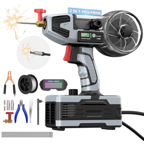
🔧【2-in-1 Professional Welder | MIG & Stick in One Machine】Eliminate the need for two separate machines. This versatile handheld welder seamlessly integrates gasless flux-core MIG and MMA (Stick) welding. Switch modes instantly with one button—perfect for going from thin sheet metal to thick outdoor repairs. Your all-in-one solution for DIY, automotive, fabrication, farm, and home projects
Preparing Joints for Stronger Stick Welds
Remove oil, moisture, paint, loose rust, and heavy scale from the weld area. A clean joint makes puddle behavior easier to read and reduces the chance of porosity, inclusions, and lack of fusion.
Do not use one bevel angle or root gap for every groove weld. Joint dimensions depend on base-metal thickness, backing, electrode, position, required penetration, code, and the welding procedure. For critical work, use the drawing and qualified WPS rather than a general online dimension.
Fit-up should be stable and consistent. Use enough tacks to maintain alignment, and clean or feather tack ends when the procedure requires the weld to pass over them.
Preheat is also procedure-specific. It may be required to slow cooling, remove moisture, or reduce hydrogen-cracking risk, but the required temperature depends on steel chemistry, carbon equivalent, thickness, restraint, filler metal, ambient temperature, and governing code. Never apply an arbitrary 150°F or 250°F rule to an unidentified steel.
Warning: Never weld on an uncleaned drum, tank, pipe, wheel, shock absorber, or sealed cavity. Residue, pressure, or trapped gas can cause an explosion. Also keep welding arcs away from chlorinated solvent vapors and allow approved cleaners to evaporate fully before welding.
Storing Low-Hydrogen Electrodes Correctly
E7018 and other low-hydrogen electrodes must stay within the storage and atmospheric-exposure limits specified by the manufacturer, WPS, and governing code. Once a sealed container is opened, the coating can absorb moisture from the air.
Lincoln Electric’s storage and redrying guidance distinguishes between unopened storage, heated holding, atmospheric exposure, and controlled redrying. Moisture-resistant classifications may have longer permitted exposure, but that does not mean they can be left indefinitely on a damp bench.
- Keep unopened packages dry and undamaged.
- Transfer opened low-hydrogen rods to the required holding storage when the procedure calls for it.
- Do not attempt to restore wet or contaminated electrodes with a kitchen oven, torch, grill, or improvised heater.
- Discard rods with cracked, flaking, contaminated, or damaged flux unless an approved procedure says otherwise.
Safety Gear and Habits for Stick Welding
Wear a welding helmet, safety glasses with side protection, dry welding gloves, flame-resistant clothing that covers exposed skin, and suitable footwear. Avoid synthetic clothing that can melt against the skin.
OSHA’s welding-filter table lists shade 10 for shielded metal arc welding with 1/16- through 5/32-inch electrodes, shade 12 for 3/16- through 1/4-inch electrodes, and shade 14 for 5/16- through 3/8-inch electrodes. Use a darker shade when needed for comfort, and never go below the applicable minimum.
Ventilation is essential. Position your head outside the fume plume and use suitable local exhaust or general ventilation. According to NIOSH’s welding-fume guidance, welding fumes commonly contain manganese, and inhaled manganese can affect the lungs and nervous system. Stainless, galvanized, painted, plated, and alloyed metals can introduce additional hazards.
A fan is not automatically adequate and can sometimes push fumes through your breathing zone. Respirators must be selected for the actual hazard and used under an appropriate respiratory-protection program when required.
Remove combustible material from the hot-work area or protect it with appropriate barriers. OSHA identifies conditions involving combustibles within 35 feet that can require a trained fire watch, and that fire watch may need to continue for at least 30 minutes after welding.
Keep the electrode holder and cables in good condition, use dry insulating gloves, stay off wet surfaces, and disconnect the machine before inspection or maintenance. Use hearing protection when chipping, grinding, gouging, or working in an environment where measured or expected noise warrants it.
Step-by-Step Guide to Running a Pull Weld
Use this practice sequence on clean, noncritical carbon-steel scrap in a flat position:
- Inspect the area. Remove combustibles, establish ventilation, put on PPE, and keep other people behind suitable welding screens.
- Identify the metal and electrode. Confirm the rod is suitable for the base metal and flat welding position.
- Check the rod data. Set the stated polarity and choose an amperage within the published range.
- Prepare the work. Clean the practice plate and attach the work clamp to bare metal.
- Set your work angle. Hold the electrode close to 90 degrees across a bead-on-plate joint, or about 45 degrees across a symmetrical fillet joint.
- Strike the arc. Use the tap or scratch method recommended for your equipment and electrode.
- Shorten the arc. Maintain a tight, controlled arc without repeatedly sticking the rod.
- Establish the drag angle. Tilt the top of the electrode approximately 5–15 degrees in the direction of travel.
- Watch the puddle. Keep the arc near the leading third and travel at a speed that maintains consistent bead width.
- Use a stringer first. On material around 1/4 inch or thinner, a straight bead is often enough. When wider coverage is required, keep side-to-side movement controlled or use multiple passes.
- Finish the crater. Avoid snapping the arc away so early that a deep crater remains. Use the electrode-specific finishing technique.
- Let the weld become safe to clean. Wear safety glasses, chip the slag away from your body and other people, then wire-brush the bead.
- Inspect the result. Look for consistent width, complete toes, acceptable profile, cracks, porosity, undercut, overlap, and remaining slag.
Run several beads with only one controlled change at a time. For example, keep current and angle steady while adjusting travel speed. That makes the cause of each improvement easier to identify.
Note: A good-looking surface does not prove internal fusion or mechanical strength. Critical welds may require a qualified procedure, certified personnel, destructive testing, or nondestructive examination.
Pros and Cons of Push and Pull Techniques
| Technique | Advantages | Limitations |
|---|---|---|
| Pull / Drag | Normal choice for flat, horizontal, and overhead SMAW; helps keep slag behind the arc; gives a clear view of the leading puddle | Too much angle can create a narrow, high-crowned bead or poor toe fusion |
| Push / Forehand | Useful for vertical-up welding when applied with the correct electrode, angle, and manipulation | Not the normal default for flat slag-producing welds; poor control can encourage slag entrapment |
Stick welding remains useful outdoors because the flux system does not depend on a separate shielding-gas cylinder at the arc. However, wind can still spread fumes and create fire hazards, and weather exposure can damage electrodes or create an electric-shock risk.
Real-World Applications for Push and Pull
For general shop practice, maintenance brackets, gates, and other noncritical carbon-steel work, use the drag technique in flat and horizontal positions unless the electrode instructions say otherwise.
For vertical-up joints, use the approved forehand technique and manipulation for the selected electrode. Vertical welding requires more skill because gravity works against puddle control.
Thin automotive body panels are usually poor candidates for ordinary stick welding. A small suitable electrode, careful heat control, short welds, backing, and excellent fit-up may help, but MIG or TIG may provide better control where those processes are available and appropriate.
Vehicle frames, suspension parts, roll structures, trailer frames, trailer hitches, lifting points, pressure piping, building steel, and similar components are not practice projects. The joint design, filler metal, welding process, preheat, sequence, acceptance criteria, and inspection must comply with the applicable engineering requirements.
Pipeline and coded structural welding must follow a qualified welding procedure. Standards such as API 1104 govern procedure qualification, welder qualification, workmanship, and inspection; they should not be reduced to a general claim that every weld must be pulled.
Advanced Tips for Multi-Pass Pull Welds
For multi-pass welding, clean every pass completely before depositing the next one. Slag left at a toe or trapped in a crater can become an inclusion even when the next bead looks smooth.
Use the pass sequence required by the joint design and WPS. A procedure may combine a fast-freeze root electrode with a low-hydrogen fill and cap electrode, but that combination is application-specific—not a universal recipe.
Stringer beads often provide more predictable fusion and heat control than one oversized weave. When weaving is permitted, keep the movement controlled and avoid spending so much time in the center that the puddle rolls over unfused edges.
Monitor interpass temperature when the procedure requires it. Do not guess at preheat or interpass values based only on plate thickness. Base-metal chemistry, strength, restraint, hydrogen level, and required mechanical properties all matter.
Before the next pass, inspect the crater, starts, stops, toes, and slag line. Grind or repair unacceptable areas using the approved method rather than burying a visible defect beneath another layer.
Conclusion
For most stick welding in the flat, horizontal, and overhead positions, pull or drag the electrode. Start with a short arc and a 5–15-degree backhand angle, keep the arc near the leading third of the puddle, and let the slag remain behind the active weld.
Vertical-up welding is the important exception: a slight push or forehand angle is commonly used to control the puddle while progressing upward. Beyond that, follow the exact electrode data, machine manual, WPS, and applicable code. Direction is one variable in a sound weld—not proof of penetration, fusion, or strength.
Frequently Asked Questions
Is pulling always better than pushing in stick welding?
No. Pulling is the normal starting technique for flat, horizontal, and overhead stick welds because it helps keep slag behind the arc. Vertical-up SMAW commonly uses a slight push or forehand angle. The electrode instructions and qualified procedure remain the final authority.
What angle should my electrode be for pulling?
For flat, horizontal, and overhead stick welding, begin close to perpendicular and tilt the top of the electrode approximately 5–15 degrees in the direction of travel. Keep the work angle centered on the joint and reduce the drag angle if the bead becomes narrow or overly convex.
Can I push with low-hydrogen rods such as E7018?
Use a drag angle in ordinary flat, horizontal, and overhead applications. A forehand angle may be used for vertical-up welding when permitted by the product instructions and WPS. Keep low-hydrogen electrodes within their specified storage and exposure limits.
Why does my pull weld have undercut?
Common causes include excessive travel speed, too much current, a long arc, an incorrect work angle, or poor pauses at the sides of a vertical weld. Shorten the arc and change one variable at a time rather than automatically increasing the drag angle.
What is the best amperage for pulling a 1/8-inch rod?
There is no universal setting. As manufacturer examples, Lincoln lists 70–130 amps DCEP for a 1/8-inch Fleetweld 5P E6010 and 90–160 amps DCEP for a 1/8-inch Excalibur 7018 MR. Check the exact electrode package and adjust for welding position and joint conditions.
Should I push when stick welding thin sheet metal?
Not as a general rule. Pushing does not reliably prevent burn-through. Use an electrode and diameter intended for light material, stay within its current range, maintain a short arc, minimize gaps, make short welds, and allow cooling time. Consider a more controllable process when appropriate.
Does a smooth-looking bead mean the weld is strong?
No. A smooth surface can hide incomplete fusion, internal slag, porosity, cracking, or insufficient penetration. Visual inspection is useful, but critical welds require the applicable procedure, welder qualification, acceptance criteria, and any specified destructive or nondestructive testing.
Sources
- Miller — Five Steps to Improving Your Stick Welding Technique — backs the drag and vertical-up angles, arc length, puddle position, travel speed, and electrode-manipulation guidance.
- Lincoln Electric — AWS Electrode Classifications — backs the electrode-classification and welding-position explanations.
- Lincoln Electric — Storing and Redrying Electrodes — backs low-hydrogen storage, exposure, and redrying guidance.
- OSHA 29 CFR 1910.252 — backs arc-welding PPE, ventilation, hot-work, fire-watch, container, and confined-space precautions.
- OSHA 29 CFR 1926.102 — backs minimum welding-filter shade guidance.
- NIOSH — Welding Fumes and Manganese — backs welding-fume and manganese exposure information.