Burn-through happens when a stick-welding arc melts completely through the base metal and leaves a hole or a dangerously thin area. It can stop a repair immediately, but the hole is usually only the final symptom. The real problem may be excessive amperage, a long arc, slow travel, poor fit-up, rust-thinned steel, or an electrode that digs too aggressively.
You’re most likely to encounter burn-through on sheet metal, thin-wall tubing, open-root joints, and edges that cannot carry much heat. It can also happen on thicker steel when a wide gap, damaged edge, or concentrated arc leaves too little metal beneath the puddle.
Preventing it comes down to controlling the whole welding system. You need an electrode suited to the material, settings based on that electrode’s package, a tight joint, a short arc, steady movement, and a plan for spreading heat instead of stacking it in one place.
Image by millerwelds
These controls matter whether you’re repairing a light gate, practicing on square tubing, or welding a component that must carry a load. A clean-looking bead is not enough if the surrounding metal has been overheated or thinned.
Quick Answer
To prevent burn-through when stick welding, use a small, soft-arc electrode such as E6013, begin near the low end of its approved amperage range, keep a short arc, and maintain steady travel. Tighten joint gaps, use short stitches, and clamp a copper or aluminum chill bar behind thin steel when access allows.
Key Takeaways
- Follow the amperage and polarity printed on your electrode package. Rod classification alone does not give one universal setting.
- E6013 usually gives you a softer, more manageable arc on thin clean steel than E6010 or E6011.
- Use a short arc, a light 5 to 15-degree travel angle, and a stringer bead instead of a wide weave.
- Wide gaps, rust-thinned edges, excessive Hot Start, and high Arc Force can cause holes even when the main amperage looks reasonable.
- Do not rely on a simple hole-fill repair for structural, suspension, lifting, pressure-containing, or code-regulated work.
At a Glance
| Time Required | About 15 to 45 minutes for preparation and scrap testing, plus the project’s welding and cooling time |
| Difficulty | Moderate; thin material gives you little time to correct an overheated puddle |
| Tools Needed | Constant-current stick welder, suitable electrodes, clamps, grinder or wire brush, measuring tools, scrap steel, and optional backing bar |
| Cost | Low to moderate if you already own the welder and PPE; cost depends on electrodes, backing material, abrasives, and replacement steel |
What Is Burn-Through and Why Does It Happen?
Burn-through, also called melt-through, occurs when the arc and molten puddle remove more metal than the joint can support. The puddle drops through, leaving an open hole or a thin edge around the weld.
It is especially common on steel below about 1/8 inch, but thickness is only one factor. Corrosion, grinding damage, a wide root gap, poor joint alignment, and welding directly on an unsupported edge can make apparently thicker material behave like thin sheet.
The most common causes include:
- Amperage that is too high for the electrode, position, or joint
- A long arc that raises arc voltage and spreads unstable heat
- Pausing or traveling too slowly
- An aggressive E6010 or E6011 arc on light, clean steel
- A wide joint gap or poorly supported edge
- Excessive Hot Start or Arc Force/DIG on an inverter welder
- Rust, pitting, previous grinding, or metal that is thinner than it appears
- A steep or inconsistent electrode angle that directs the arc into one edge
- Repeated welds placed in the same area without cooling time
Burn-Through, Undercut, and Lack of Fusion Are Different
A hole through the work is burn-through. A groove melted beside the weld toe is undercut. A bead that sits on top without bonding correctly is lack of fusion. All three can weaken a joint, but they require different corrections.
- Burn-through: Reduce concentrated heat, support the puddle, tighten the gap, or use shorter welds.
- Undercut: Correct amperage, angle, arc length, and travel speed so the edge fills instead of washing away.
- Lack of fusion: Do not keep lowering amperage blindly. Improve cleaning, angle, arc placement, or travel speed until the base metal fuses correctly.
The goal is not to use the lowest possible amperage. The goal is to use the lowest setting that still produces a stable arc and sound fusion without collapsing the joint.
Choosing the Right Electrode for Thin Steel
Electrode selection changes the arc force, penetration profile, slag behavior, required polarity, and usable current range. For thin steel, you usually want a small electrode with a soft, stable arc rather than one designed to dig through scale or form an open-root keyhole.
Products Worth Considering

【 GENERAL‑PURPOSE E6013 FOR SHEET METAL 】 Smooth, forgiving welds-mild steel, sheet metal, thin gauge steel, ductwork, brackets, and repairs. Runs clean on 110V stick welders and basic welding tools.

MODEL: E6013 is a mild-steel general purpose rod. It operates on AC or DC welding current and works well on low voltage AC machines.

Product Introduction: E6013 welding rod is suitable for both AC and DC applications and can be used for all position welding
E6013: A Practical Starting Point
E6013 is commonly chosen for clean sheet metal and light fabrication because it can operate at relatively low current and has a softer arc than cellulosic rods. Lincoln Electric describes its Fleetweld 37 E6013 as suitable for low-amperage sheet-metal work.
A 3/32-inch E6013 is widely available, but it is not automatically suitable for every sheet thickness. On very light material, a 1/16-inch or 5/64-inch E6013 may provide better control if your machine and electrode manufacturer support that size. Always use the current and polarity printed on the package.
Pro Tip: Buy electrodes from a manufacturer that prints a clear operating range and polarity on the container. Start near the lower end on matching scrap, then increase current in small steps only when the arc is unstable or fusion is inadequate.
E7018: Strong, Low-Hydrogen Weld Metal
E7018 is a low-hydrogen electrode that generally provides medium penetration, not the aggressive deep penetration associated with E6010 or E6011. It is widely used when a procedure calls for low-hydrogen weld metal, good mechanical properties, or improved crack resistance.
It can still burn through thin steel because its usable current may be too high for the joint. As one product-specific example, Lincoln Excalibur E7018 lists 70 to 110 amps on DCEP and 80 to 120 amps on AC for its 3/32-inch electrode. Other brands can differ.
Do not assume E7018 is the best choice simply because the finished weld must be strong. Electrode selection must match the base metal, joint, service conditions, design requirements, and any applicable welding procedure. Low-hydrogen electrodes must also be stored and handled according to their manufacturer’s moisture-control instructions.
E6010 and E6011: Aggressive Penetration
E6010 and E6011 produce fast-freezing, digging arcs. They are useful for pipe roots, repair work, and steel that cannot be cleaned as thoroughly as new plate. That same arc can remove the edge of thin material quickly.
E6010 is commonly designed for DCEP, while E6011 products can often operate on AC and may also allow DCEP. Check the exact package before connecting the leads. Do not change polarity merely to reduce penetration unless the electrode manufacturer approves that polarity.
If a 3/32-inch E6010 or E6011 keeps opening holes in clean light-gauge steel, switching to a small E6013 is usually more effective than trying to force the aggressive rod to run far below its stable range.
Electrode Diameter Matters
A smaller electrode normally runs at lower current and creates a smaller puddle. For light steel, consider the smallest diameter your welder can run smoothly and your electrode manufacturer approves.
- 1/16 inch: Useful for very light work when available, but it can be delicate and harder to find.
- 5/64 inch: A useful middle size offered by some manufacturers.
- 3/32 inch: Common for light fabrication, although it can still be too hot for automotive-style sheet.
- 1/8 inch and larger: Generally better suited to thicker material and higher deposition requirements.
Note: Manual stick welding is often a poor choice for extremely thin sheet. Short-circuit MIG or controlled TIG welding may provide a smaller, easier-to-manage heat input. Choosing another process is good judgment, not a failure of stick-welding skill.
Setting Up the Welder to Avoid Burn-Through
Stick welders use constant-current output, so amperage is the main setting. Modern inverter machines may also let you adjust Hot Start and Arc Force, sometimes labeled DIG.
Products Worth Considering

DUAL-VOLTAGE STICK WELDER: Runs on 120V (up to 110A) or 240V (up to 210A) — no dedicated power setup needed. Portable arc welder ready for garage, farm, job shop, maintenance repair, or light production work.

MULTIFUNCTIONAL: A 4-in-1 welder, capable of Flux Core MIG/Gas MIG/ Stick/Lift TIG (need to purchase extra tig lift torch). This unit caters to a wide range of welding applications and meets your various welding needs.
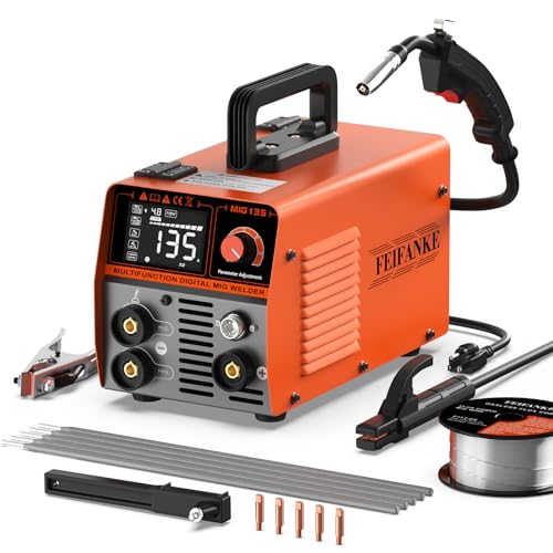
3 IN 1 MULTI-PROCESS WELDER: This flux core welder with 3 welding modes-Flux Core Gasless MIG, Lift TIG (extra torch required) and Stick Welding meets your different requirements. Perfect for DIY repairs, automotive work, farm equipment, and creative metal crafts around your home and garage
Amperage: Begin Low and Test Upward
Set the welder near the lower end of the electrode manufacturer’s approved range. Run a bead on scrap that matches the project’s alloy, thickness, joint type, position, and fit-up. Increase current by about 5 amps at a time when the arc repeatedly goes out, the rod sticks despite correct technique, or the bead fails to fuse.
Signs that the current may be too high include:
- An excessively fluid or rapidly widening puddle
- Edges disappearing ahead of the bead
- Heavy spatter or undercut
- An electrode that becomes unusually hot or glows before it is consumed
- A loud, harsh arc compared with the same rod at a lower setting
Signs that the current may be too low include frequent sticking, a stuttering arc, a tall rope-like bead, trapped slag, or weld metal that sits on the surface without tying into both sides.
Polarity: Follow the Electrode Label
Polarity affects arc behavior, but the electrode coating determines which connections are permitted. Some E6013 products run on AC, DCEP, or DCEN. Many E7018 products run on DCEP, while AC-rated versions may also run on AC. E6010 is normally associated with DCEP.
Use the package or manufacturer data sheet as the authority. Running an unapproved polarity can create an unstable arc, poor slag behavior, porosity, or inadequate weld properties.
Reduce Hot Start When Starts Blow Out the Edge
Hot Start temporarily raises output current as the arc begins. It helps prevent sticking, but a strong Hot Start can punch through a thin edge before you establish travel.
If your machine provides an adjustable Hot Start:
- Reduce it toward a soft or low setting.
- Strike the arc on a tack or slightly inside the joint instead of directly on a fragile edge.
- Begin moving as soon as the puddle forms.
- Use a run-on tab when the joint and project allow it.
Lower Excessive Arc Force or DIG
Arc Force temporarily increases current when the arc becomes very short or the electrode approaches a short circuit. It can help prevent sticking, especially with digging electrodes, but an aggressive setting may add unwanted heat on thin steel.
Start with a soft or neutral Arc Force setting when using E6013 on light material. Increase it only when the rod repeatedly sticks despite correct amperage, angle, and arc control.
Confirm the Work Lead Connection
Clamp the work lead to clean bare metal close enough to provide a reliable circuit. A poor connection can make the arc erratic and tempt you to raise amperage unnecessarily. Do not place the clamp where welding current must pass through bearings, electronic modules, hinges, cables, or other vulnerable components.
Mastering the Welding Technique
Settings put you in the usable range, but your hand controls where the heat goes. On thin steel, small changes in arc length, angle, and speed can change the puddle within a second.
Keep a Short, Controlled Arc
Miller’s stick-welding guidance recommends an arc length that generally does not exceed the diameter of the electrode’s metal core. Thin material often benefits from an even tighter controlled arc, provided the rod does not stick.
A long arc raises voltage, increases spatter, widens the heat pattern, and makes the puddle harder to control. Move your head or body for a better view rather than lifting the electrode farther away.
Use the Correct Travel and Work Angles
Travel angle and work angle are not the same:
- Travel angle: The rod’s tilt forward or backward along the weld path.
- Work angle: The rod’s angle across the joint, such as 90 degrees into a butt joint or approximately 45 degrees into an equal T-joint.
For common flat and horizontal stick welds, begin with a light drag angle of about 5 to 15 degrees. Keep the work angle centered so one edge does not receive most of the arc force. Joint shape, welding position, electrode instructions, and an approved procedure can require a different angle.
Maintain Steady Travel
Move quickly enough to keep the puddle compact, but not so fast that the bead becomes narrow and fails to fuse. Watch the leading edge of the puddle rather than staring at the bright arc.
If the puddle becomes wider and more fluid with each second, increase travel slightly or stop before the edge collapses. If the bead becomes thin, irregular, or fails to wet into both sides, slow down slightly or review the amperage.
Use Stringer Beads Instead of Wide Weaves
A wide weave keeps the arc over the joint longer and increases total heat input. On light steel, use a straight stringer bead or a very small controlled motion. Build width with separate passes only when the joint design and remaining thickness can support them.
Control Starts, Stops, and Craters
Starts and stops are common burn-through points because heat becomes concentrated at an edge or crater.
- Start on an existing tack when possible.
- Do not hold the arc in place while waiting for a large puddle.
- Before stopping, move back briefly over the crater if the electrode and joint allow it.
- Clean slag completely before restarting.
- Restart slightly ahead of the crater, then move back into it and continue forward.
Preparing the Workpiece Properly
Good preparation gives the puddle enough sound metal to bridge the joint. Poor preparation forces you to compensate with the arc, which usually adds more heat and uncertainty.
Clean to Sound Metal
Remove oil, grease, moisture, rust, mill scale, paint, and other contamination from the weld zone. Clean both sides when practical because coatings on the back can still create fumes or contaminate the weld.
Do not keep grinding deeply into thin steel. Over-grinding reduces the remaining wall thickness and can create a new burn-through problem.
Inspect for Rust-Thinned or Damaged Steel
Tap, measure, or probe suspect areas before welding. If rust has left flaky edges, deep pits, or metal that flexes easily, cut back to sound material and fit a proper patch. Trying to bridge severely thinned steel usually makes the hole larger.
Make the Fit-Up as Tight as the Joint Allows
There is no universal 1/16-inch maximum gap for every weld. The allowable opening depends on thickness, joint design, electrode, required penetration, and any governing welding procedure.
For an ordinary thin butt joint without a specified root opening, aim for a near-zero, even gap. Correct distorted or uneven edges before welding. Do not use extra amperage to compensate for poor fit-up.
Tack the Joint Before Running a Bead
Place small, sound tacks at suitable intervals to hold alignment and stop the gap from opening as the metal expands. On a long seam, work from the center outward or alternate locations so shrinkage does not pull the joint apart.
Grind oversized or cracked tacks before welding over them. Clean all tack-weld slag.
Use a Backing Bar or Chill Bar
A clean copper or thick aluminum bar clamped tightly behind the joint can absorb heat and physically support the molten puddle. Miller recommends backing or chill bars as one method of reducing heat buildup on thin material.
Copper is often preferred because ordinary steel weld metal is less likely to fuse to it. A thick aluminum chill bar can also work when it remains solid and is kept out of the arc. Do not intentionally strike the electrode on the backing bar.
If you use steel backing, assume it may fuse to the weld and become part of the joint. Do not use an improvised permanent backing strip where the joint design or welding procedure prohibits it.
Warning: Never weld an unknown tank, drum, fuel component, pressure container, or closed section merely because it appears empty. Residues and trapped vapors can ignite or explode. Coatings and plated metals may also release hazardous fumes. Identify the material and follow an approved cleaning, ventilation, and hot-work procedure.
Stick Welding Thin Metal Without Burn-Through
Thin metal gives you little time between forming a puddle and losing the edge. The safest approach is to reduce the amount of continuous arc time and spread each weld’s heat over a larger area.
Use the Smallest Suitable Electrode
Select the smallest electrode that your machine can run reliably and that still meets the joint’s requirements. Begin at the low end of its approved current range and confirm fusion on scrap before touching the project.
Stitch Weld in Short Bursts
Instead of running one long bead, make a short weld and stop before the puddle grows uncontrollably. A burst may last roughly one or two seconds on some thin joints, but use the puddle rather than a stopwatch as your guide.
Let the glow and concentrated heat fade before placing the next stitch. Clean slag from every area that the next weld will overlap.
Skip Around Long Seams
Place short welds at separated points, then return later to fill the spaces. Alternate from one side of the assembly to the other instead of welding adjacent sections in sequence.
This skip-welding pattern reduces local heat buildup and distortion. It does not eliminate the need for adequate fusion between stitches.
Choose the Joint That Gives the Edge Support
- Butt joint: Most sensitive to gaps and edge collapse. Use accurate fit-up and backing when allowed.
- Lap joint: Usually more forgiving because the overlapping sheet supports the puddle, but excessive heat can still melt the exposed edge.
- T-joint or fillet: Direct the work angle into the root without concentrating the arc on the thinner member.
- Edge joint: Highly vulnerable because both edges can melt away. Use minimal continuous arc time and consider a different joint design when possible.
Be Careful With Vertical-Down Welding
Some E6013 products are designed to run vertical down on sheet metal, and the faster travel can reduce penetration. Use that technique only when the electrode manufacturer, joint, service conditions, and applicable procedure allow it.
Do not substitute vertical-down welding for a required vertical-up structural procedure merely to reduce burn-through.
Common Problems and Corrections
| What You See | Likely Cause | Correction |
|---|---|---|
| The edge suddenly falls away | Too much local heat, thin edge, wide gap, or aggressive Hot Start | Stop, lower concentrated heat, improve fit-up, reduce Hot Start, and use backing |
| The puddle becomes very wide and fluid | Current too high, travel too slow, or excessive weaving | Reduce current slightly, move steadily, and use a stringer bead |
| The rod sticks repeatedly | Current too low, arc too short, poor work connection, damp or unsuitable rod | Check the clamp and electrode, then increase current in small steps |
| The bead sits high without tying into the sides | Low current, excessive travel speed, poor cleaning, or wrong arc placement | Clean again, center the work angle, and adjust current or speed |
| A groove forms beside the bead | Undercut from high current, long arc, poor angle, or excess speed | Shorten the arc, correct the angle, and balance current with travel |
| Every restart creates a hole | Hot Start, striking on a thin edge, or pausing in the crater | Lower Hot Start and restart on sound weld metal before moving into the crater |
| The hole grows when you try to fill it | Surrounding metal is still hot, unsupported, contaminated, or rust-thinned | Stop, cool naturally, clean and inspect, add backing, or cut back to sound steel |
How to Repair a Small Burn-Through Hole
A small hole in noncritical mild-steel fabrication may be repairable if the surrounding metal remains sound. Do not use this method as proof that a structural or pressure-containing component is safe.
- Stop welding immediately. Continuing while the area is hot usually enlarges the hole.
- Let the joint cool naturally. Do not quench a critical weld unless the approved procedure specifically allows it.
- Inspect the surrounding steel. Remove slag and grind only enough to expose sound metal. Cut out rust-thinned or cracked material.
- Correct the original cause. Lower excessive current or Hot Start, tighten the gap, change the electrode, or improve your technique.
- Clamp a copper backing bar behind the hole. Make full contact so the backing supports the puddle.
- Build from the sound edge inward. Place very short deposits around the perimeter rather than aiming the arc into the center of the hole.
- Allow cooling between deposits. Clean slag before overlapping each new weld.
- Inspect both sides. Look for remaining voids, cracks, undercut, incomplete fusion, and excessive grinding.
Warning: Have a qualified welder, inspector, or engineer evaluate burn-through on trailer couplers, vehicle frames or suspension parts, lifting equipment, pressure vessels, roll cages, structural connections, or any joint governed by a code or welding procedure. Grinding the surface smooth does not prove the repair is sound.
Safety Considerations
Burn-through increases the chance of falling molten metal, hidden fires, damaged components, and an unsafe joint. Wear flame-resistant clothing, dry welding gloves, suitable footwear, hearing protection when needed, and a welding helmet with the correct filter shade.
The OSHA welding eye-protection fact sheet lists minimum shade 7 for shielded metal arc welding below 60 amps and minimum shade 8 from 60 to 160 amps. Follow the helmet manufacturer’s instructions, applicable workplace rules, and any requirement that calls for a darker shade. Wear safety glasses with side protection under the helmet to protect against slag and grinding debris.
Control Fumes and Coatings
Welding fumes can contain hazardous metals and gases. Use effective ventilation that moves fumes away from your breathing zone without disrupting the arc. Follow the requirements that apply to your workplace and material.
OSHA’s welding requirements include added controls for confined spaces and for zinc, lead, cadmium, and other hazardous materials. Do not weld through unknown paint, plating, sealant, undercoating, or chemical residue.
Prevent Fire
- Remove combustible material from the hot-work area.
- Check the opposite side of walls, floors, panels, and enclosed sections.
- Keep a suitable fire extinguisher available.
- Use a fire watch when sparks or molten metal can reach a hidden area.
- Inspect the area after welding for smoldering material.
Prevent Electrical Shock
- Keep gloves, clothing, electrode holders, and work areas dry.
- Replace damaged cables, connectors, and insulation.
- Do not touch the electrode and workpiece with bare skin at the same time.
- Use additional protection in damp, wet, elevated, or confined locations.
- Turn off and isolate equipment before changing internal connections or performing maintenance.
Electrode Choices for Thin Metals
| Electrode | Arc Character | Current and Polarity Guidance | Thin-Metal Use | Main Caution |
|---|---|---|---|---|
| E6013 | Soft, stable arc with moderate or relatively light penetration compared with cellulosic rods | Follow the package; approved AC, DCEP, and DCEN options vary by product | Often the most manageable common stick electrode for clean sheet and light fabrication | A 3/32-inch rod can still be too hot for very thin sheet |
| E7018 | Low-hydrogen coating and generally medium penetration | Product-specific; Lincoln Excalibur 3/32-inch lists 70–110 amps DCEP and 80–120 amps AC | Useful when the joint or procedure requires low-hydrogen weld metal | Current range and puddle size can be difficult on light sheet; storage matters |
| E6010 | Deep, digging, fast-freezing arc | Normally DCEP; use the product’s listed range | Specialized roots and repair situations | High burn-through risk on thin clean steel; some small inverters run it poorly |
| E6011 | Digging, fast-freezing arc similar in purpose to E6010 | Many products allow AC and DCEP, but verify the package | Repair work and less-than-perfectly-clean steel | Aggressive arc can remove thin joint edges quickly |
Step-by-Step Guide to Prevent Burn-Through
- Identify the material. Confirm the alloy, actual thickness, coating, previous repairs, corrosion, and whether the part carries a critical load.
- Choose the process honestly. Use stick welding only when the material is thick enough and the joint gives you reasonable puddle control.
- Select a suitable electrode. For clean light steel, begin with a small E6013 unless the design or procedure requires something else.
- Read the package. Confirm the electrode’s approved amperage range, polarity, positions, and storage requirements.
- Clean and fit the joint. Remove contamination, cut back rust-thinned steel, align the edges, and minimize unintended gaps.
- Tack and support the work. Add enough sound tacks to prevent movement and clamp a backing bar behind vulnerable joints when permitted.
- Set the machine conservatively. Begin near the lower end of the approved range. Reduce adjustable Hot Start and Arc Force when they create excessive heat.
- Test matching scrap. Reproduce the project’s joint, position, thickness, and gap rather than testing on unrelated heavy plate.
- Use controlled technique. Keep the arc short, maintain the correct work angle, use a 5 to 15-degree travel angle, and watch the puddle’s leading edge.
- Limit continuous arc time. Use stringers, short stitches, and a skip sequence instead of a long weave.
- Respond to the puddle. Stop or move sooner when it becomes excessively wide, bright, or fluid. Do not wait for a hole to appear.
- Clean and inspect. Remove slag, examine both sides, and look for holes, undercut, cracks, trapped slag, lack of fusion, and excessive distortion.
Conclusion
Preventing burn-through when stick welding requires more than turning the amperage down. You need a suitable electrode, an approved polarity, sound metal, close fit-up, controlled machine features, a short arc, and steady movement.
E6013 is often the most manageable common rod for clean light steel, while E6010 and E6011 demand more caution because of their digging arcs. E7018 provides low-hydrogen weld metal and medium penetration, but its current range can still make it unsuitable for very thin sheet.
Test on matching scrap, make one adjustment at a time, and inspect the finished joint instead of judging it only by bead appearance. When the material is severely rusted, extremely thin, structurally critical, or governed by a welding code, change the repair method or involve a qualified professional rather than trying to fill the problem with more weld metal.
Frequently Asked Questions
What causes burn-through in stick welding?
Burn-through occurs when concentrated heat removes more base metal than the joint can support. Common causes include excessive current, a long arc, slow travel, a digging electrode, wide joint gaps, rust-thinned steel, excessive Hot Start, and repeated welding in one small area.
Can I weld thin metal with a stick welder?
Yes, within limits. Use a small soft-arc electrode, tight fit-up, conservative settings, a short arc, and short stitches. Extremely thin automotive-style sheet is usually easier to control with short-circuit MIG or TIG welding.
What is the best stick electrode for thin steel?
A small E6013 is often the best common starting point for clean thin steel because it produces a softer arc than E6010 or E6011. Choose the smallest suitable diameter and follow the exact current and polarity listed by the electrode manufacturer.
Should I lower amperage every time I see burn-through?
Not automatically. First check the gap, remaining metal thickness, arc length, travel speed, angle, Hot Start, Arc Force, and electrode type. Lowering current too far can replace burn-through with sticking, slag inclusions, or lack of fusion.
How do I fix a small burn-through hole?
Stop and let the area cool, clean back to sound metal, correct the original heat or fit-up problem, and clamp a copper backing bar behind the hole. Add very short deposits from the sound perimeter inward. Critical structural or pressure-containing repairs require qualified evaluation.
Does a longer arc reduce the chance of sticking?
It may reduce immediate sticking, but it creates other problems. A long arc raises voltage, increases spatter, widens the heat pattern, and makes the puddle less stable. Use correct amperage and a controlled arc that generally does not exceed the electrode core diameter.
Is burn-through a safety concern?
Yes. It can leave an undersized or cracked joint, release molten metal into a hidden area, damage nearby parts, and start fires. Treat burn-through on load-bearing, lifting, pressure-containing, suspension, or code-regulated components as a serious defect.
Sources
- Miller: Five Steps to Improving Your Stick Welding Technique — amperage adjustment, arc length, travel angle, speed, and stringer guidance
- Miller: Factors for Selecting the Right Stick Electrode — soft-arc E6013 selection and digging E6010/E6011 characteristics
- Lincoln Electric: Fleetweld 37 E6013 — low-amperage sheet-metal application
- Lincoln Electric: Excalibur E7018 — product-specific polarity and operating-current data
- Hobart Brothers: 7018 Welding Rod Amperage — low-hydrogen coating and medium-penetration classification
- OSHA 29 CFR 1910.252 — welding PPE, ventilation, fumes, coatings, confined-space, and electrical safety requirements