A leaking HVAC copper line can turn a small repair into a costly system problem fast. Brazing produces a durable refrigerant-line joint, but it also involves an open flame, compressed gas, high system pressures, and refrigerant-handling rules. Clean preparation, a controlled dry-nitrogen purge, correct filler metal, and equipment-specific testing are essential.
This guide explains how to braze HVAC copper pipe without using soft solder. It also shows where a homeowner or beginner should stop. Practicing on clean scrap copper is reasonable, but opening, repairing, evacuating, or charging an installed refrigerant system normally requires trained personnel, specialized tools, and compliance with local rules.
Quick Answer
Braze HVAC copper by cutting and deburring the tube, cleaning both mating surfaces, flowing dry nitrogen through an open line, heating the fitting evenly, and letting the hot joint melt the correct brazing alloy. Recover refrigerant first, protect nearby components, and follow the equipment manual for pressure testing, evacuation, and charging.
Key Takeaways
- Never braze a charged refrigerant line or heat tubing that is sealed at both ends.
- Use a low, controlled dry-nitrogen sweep with an open exit while brazing to limit oxide scale inside the tubing.
- Choose the filler metal for the base metals and equipment instructions; copper, brass, steel, and compressor fittings do not all use the same alloy or flux.
- Use dry nitrogen for pressure testing, never oxygen, compressed air, fuel gas, or another flammable gas.
- Test pressure, evacuation targets, charging methods, and A2L precautions are equipment-specific.
At a Glance
| Time Required | About 1–3 hours for an accessible repair, including setup, testing, and evacuation; recovery, leak diagnosis, or moisture removal can take longer. |
| Difficulty | Advanced. Practice joints are suitable for supervised training; installed refrigerant-system work should be handled by a qualified technician. |
| Tools Needed | Suitable torch, filler rod, tubing tools, nitrogen cylinder with regulator and flow control, heat protection, PPE, fire extinguisher, pressure-test equipment, vacuum pump, and micron gauge. |
| Cost | Practice copper and filler are inexpensive, but a complete refrigerant-recovery, nitrogen, vacuum, testing, and A2L-compatible service setup is costly. Professional service is usually more practical for one repair. |
What Is Brazing and Why Use It for HVAC Copper Lines?
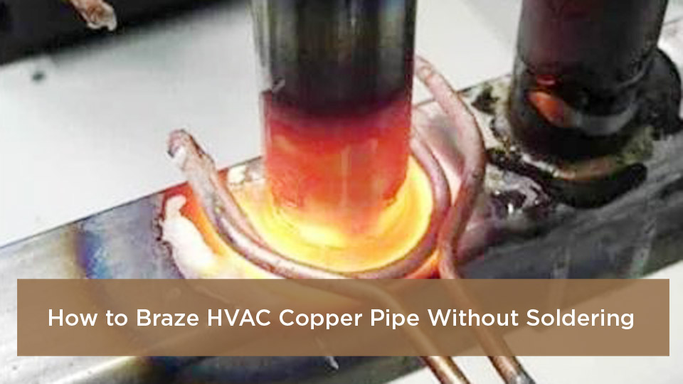
Brazing joins metal by melting a filler alloy into the narrow space between a tube and fitting. The base copper remains solid. Heat draws the molten filler through the joint by capillary action.
The main technical difference between soldering and brazing is filler-metal temperature. Soldering uses filler that melts below about 840°F or 450°C. Brazing uses filler above that threshold, while still remaining below the melting temperature of the copper.
A sound brazed joint comes from clean metal, close fit, balanced heat, and capillary flow—not from piling extra alloy around the outside.
HVAC copper lines carry refrigerant under changing pressure and temperature and may receive vibration from compressors and fans. Many equipment manufacturers therefore specify brazed joints for refrigerant piping. One Trane installation guide, for example, directs installers reusing refrigerant lines to make sure the joints are brazed rather than soft-soldered. See the applicable equipment installation instructions before choosing a joint method.
Many copper-to-copper brazing rods contain phosphorus. On clean copper, the phosphorus can act as a fluxing agent, so separate chemical flux is often unnecessary. Copper-to-brass and other mixed-metal joints commonly require a compatible flux and may require a different filler alloy.
Warning: Never braze a line that still contains refrigerant or pressure. Heating trapped refrigerant can raise pressure, produce hazardous decomposition products, or create an ignition risk. Recover the refrigerant legally, verify both sides of the system are at a safe pressure, and keep the tubing vented before cutting or heating.
Key Differences Between Brazing and Soldering HVAC Lines
| Aspect | Brazing | Soldering |
|---|---|---|
| Filler temperature | Above about 840°F or 450°C | Below about 840°F or 450°C |
| Common filler | Copper-phosphorus or silver-bearing brazing alloy selected for the base metals | Tin-based soft solder |
| Typical HVAC use | Refrigerant piping when approved by the equipment manufacturer | Some plumbing and other lower-temperature applications |
| Flux | Often unnecessary for copper-to-copper BCuP joints; commonly required for brass or mixed metals | Usually required for copper plumbing solder |
| Heat control | Critical because valves, filter-driers, insulation, paint, and internal components can be damaged | Lower heat, but nearby components still require protection |
| Main risk | Fire, oxidation, component overheating, improper filler selection, and refrigerant hazards | Weak or unapproved refrigerant-line joints and flux contamination |
Do not assume brazing is approved merely because the tubing is copper. Some equipment permits approved mechanical connections, while other products specify brazing. The equipment installation manual, local code, and fitting listing control the method.
Certification, Refrigerant Recovery, and A2L Safety
In the United States, the EPA Section 608 program prohibits intentional venting of regulated refrigerants during service. Technicians performing work that could release refrigerant generally need the appropriate Section 608 certification and must use compliant recovery equipment and service practices. State or local contractor licensing may add further requirements.
Practice brazing on unused, open scrap copper does not involve refrigerant. Cutting into an installed line, replacing a compressor, opening service valves, evacuating a system, or adding refrigerant is a different level of work. Refrigerant in a charged system must be recovered to the applicable level before the circuit is opened. Review the EPA’s stationary refrigeration service-practice requirements.
Newer equipment may contain an A2L refrigerant, including R-32 or R-454B. These refrigerants have lower flammability than propane, but they still require ignition control, ventilation, approved service tools, appropriate leak-detection equipment, and manufacturer-specific procedures.
Warning: Do not apply a generic brazing procedure to an A2L system. Read the unit label and installation manual before service. A current Daikin R-32 installation manual, for example, adds mandatory A2L joint, pressure-test, evacuation, leak-detection, and ignition-control instructions.
Stop and call a qualified HVAC technician when you cannot positively identify the refrigerant, cannot recover the entire charge, lack A2L-rated equipment where required, cannot isolate electrical power, cannot establish ventilation, or do not know the manufacturer’s pressure-test limit.
What You Need Before Brazing HVAC Copper Pipe
Good results start with tools that match the tubing, filler alloy, equipment, and refrigerant. A weak or oversized torch, dirty tube, damaged fitting, or uncontrolled nitrogen supply can turn a small repair into a leak or component failure.
- Air-acetylene, oxy-acetylene, oxy-propylene, or another torch approved for the joint and filler alloy
- Correct torch tip for the tube diameter and mass of the fitting
- HVAC-rated brazing filler approved for the base metals and equipment
- Dry-nitrogen cylinder secured upright
- Nitrogen regulator, pressure gauge, flowmeter or brazing regulator, hose, and suitable relief protection
- Tubing cutter, reamer, and deburring tool
- Dedicated emery cloth or clean stainless-steel brush
- Wet rags, heat-blocking compound where approved, fire blanket, and flame-resistant heat shields
- Safety glasses or suitable shaded eye protection, leather gloves, flame-resistant clothing, and closed footwear
- Appropriate fire extinguisher immediately available
- Dry-nitrogen pressure-test equipment rated for the required test pressure
- Vacuum-rated hoses, core-removal tools where appropriate, vacuum pump, and micron gauge
- Refrigerant recovery and charging equipment when working on an installed system
- A2L-compatible tools when the equipment manufacturer requires them
Use an oxy-fuel torch only with compatible regulators, hoses, flashback protection, and manufacturer procedures. Secure cylinders away from the flame and hot work. OSHA requires suitable hot-work fire precautions and readily available extinguishing equipment; its fire-prevention requirements provide a useful workplace reference.
Pro Tip: Build several scrap joints in the same tube sizes you expect to service. Cut each finished joint lengthwise so you can see whether filler reached the bottom of the socket instead of judging only the outside fillet.
Products Worth Considering

Complete Kit: Ideal for HVAC & Light Duty Brazing - Designed specifically for light-duty brazing and welding jobs, this kit is your go-to tool for HVAC repairs, metal crafts, and other precision tasks. Its portable design is perfect for on-the-go professionals
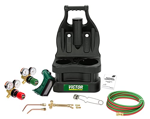
The Portable Tote from Victor features a molded, plastic carrying case with an ergonomic handle and balanced design for easy carrying.

3.6ft Hose for Extra Reach: This propane torch kit have a 3.6ft long gas hose that connects the torch to your propane/Map source, it's handy to get into small places. Warm tips: Gas bottles don't like being upside down
How to Prepare the Workspace and Copper Pipes
Preparation does most of the work. Clean copper, square cuts, proper fit, an open nitrogen path, and a safe work area give the filler a clear route through the joint.
Shut off every electrical source that can energize the equipment. Some systems have more than one disconnect. Lock and tag the disconnects where workplace procedures require it, and verify the circuit is de-energized before touching wiring or controls.
Remove or shield insulation, wood dust, paper, stored chemicals, leaves, and other combustibles. Protect wall cavities and hidden surfaces behind the joint. Keep a suitable extinguisher ready and arrange a fire watch when conditions require one. Remain on site long enough after brazing to inspect concealed and nearby areas for heat, smoke, or smoldering material.
If the system contains refrigerant, recover it with approved equipment. Confirm pressure on both high and low sides, because trapped refrigerant can remain behind valves or compressor seals. Do not rely on one gauge connection alone when the system design can isolate sections.
Cut the copper square with a tubing cutter. Avoid overtightening the cutter, which can reduce the tube diameter. Ream and deburr the inside and outside edges without dropping chips into the line.
Clean the outside of the tube and the inside of the fitting to bright metal. Use dedicated emery cloth or a clean brush. Wipe away loose particles with a clean, lint-free cloth.
Avoid unnecessary solvents. If the equipment or filler manufacturer permits a residue-free cleaner, keep it out of the refrigerant circuit and allow it to evaporate completely before lighting the torch. Never heat chlorinated cleaner residue.
Dry-fit the joint. The tube should remain round, enter the socket fully, and fit closely enough for capillary action without being hammered into place. Replace a fitting that is cracked, distorted, contaminated, or excessively loose.
Cleaning Techniques That Improve Brazing Flow
Clean mechanically with even strokes. Deep scratches are unnecessary and may create leak paths. Do not handle the cleaned joint surfaces with bare, oily fingers.
Keep refrigerant tubing capped while routing it so dust and moisture cannot enter. Open it only when you are ready to assemble, purge, and braze.
Blow loose debris out safely before final assembly. Do not use shop air to pressurize or dry an assembled refrigeration circuit. The finished mating surfaces should look bright, dry, and free of oil, oxide, burrs, and fingerprints.
Step-by-Step Guide to Brazing HVAC Copper Pipe
Follow the same order every time. A written sequence reduces the chance of skipping refrigerant recovery, nitrogen flow, valve protection, pressure testing, or evacuation.
- Identify the equipment and refrigerant. Read the data plate and installation manual. Confirm the approved joint method, filler requirements, A2L precautions, pressure-test limit, and evacuation procedure.
- Recover refrigerant and isolate power. If the circuit is charged, recover the refrigerant legally and verify that all sections to be opened are at a safe pressure. Shut off and verify electrical power.
- Cut, deburr, clean, and assemble the joint. Make a square cut, remove burrs, clean both mating surfaces, and seat the tube fully without contaminating it.
- Protect nearby parts. Remove valve cores when the equipment instructions call for it. Shield wiring, insulation, paint, cabinets, filter-driers, TXVs, and service valves. Place wet rags or approved heat-blocking material where directed.
- Start a controlled dry-nitrogen sweep. Connect a regulator and low-flow control. Nitrogen must enter one side, pass through the joint area, and leave through an open outlet. Do not seal both ends or build test pressure while heating.
- Light and adjust the torch. Follow the torch manufacturer’s procedure. With oxy-acetylene, use the flame specified for the filler and component, commonly neutral or slightly reducing. Keep the flame away from hoses, cylinders, wiring, and combustible surfaces.
- Heat the tube and fitting evenly. Begin on the heavier fitting area and move around the circumference. Sweep the flame rather than holding it in one spot. Heat the assembly, not the end of the filler rod.
- Feed filler into the hot joint. Touch the rod to the joint opposite or slightly away from the flame. The heated metal should melt the filler. Move the heat so capillary action draws alloy around and into the socket.
- Stop when the joint is filled. Remove the rod and flame as soon as a complete, even fillet appears. Excess alloy can run inside the tube and restrict flow; it cannot repair dirty metal or poor fit.
- Cool and inspect according to the component instructions. Keep the tube supported and continue the nitrogen sweep while the joint drops below oxidation temperature. Let plain couplings cool undisturbed. For service valves or other heat-sensitive parts, follow the manufacturer’s wet-rag or quenching directions.
- Pressure test with dry nitrogen. After the assembly is cool, stop the purge, configure the test equipment, and pressurize only to the value specified by the equipment manufacturer and the lowest-rated component. Check all joints with an approved bubble solution or compatible detector.
- Evacuate and perform a standing vacuum test. Release nitrogen safely, connect a vacuum pump and micron gauge with vacuum-rated hoses, evacuate to the manufacturer’s target, isolate the pump, and watch for vacuum rise.
- Charge and commission the system. Open service valves and charge only by the equipment procedure, refrigerant type, line length, and operating conditions. Check for leaks and verify system performance.
Do not melt the rod directly in the flame. If the filler beads up or falls off, stop and diagnose the problem. The joint may be too cool, dirty, oxidized, poorly fitted, or heated in the wrong area.
A useful compressor-fitting heat pattern is to warm the tube first, move heat toward the fitting, and then use brief heat beyond the joint to draw filler inward. Copeland illustrates this sequence in its scroll-compressor brazing bulletin. Follow the specific compressor instructions because copper-plated steel stubs do not behave exactly like a plain copper coupling.
How to Set the Nitrogen Purge Safely
The nitrogen used during brazing is a sweep, not a pressure test. Its job is to displace oxygen inside the tubing while leaving through an open path.
- Secure the cylinder and use a regulator designed for nitrogen.
- Use a flowmeter or brazing regulator to create only the low flow needed to displace air.
- Keep an outlet open and confirm gas is leaving before applying heat.
- Do not cap, pinch, or close the outlet while the line is hot.
- Do not direct the outlet toward a person, flame, confined space, or debris.
- Use ventilation because nitrogen can displace breathable oxygen.
- After brazing, stop the sweep before configuring the separate standing pressure test.
Note: Manufacturers express brazing flow in different ways, including low regulator pressure or flow rate. Do not copy a number from another unit. Use the equipment instructions and a regulator that provides stable low flow without pressurizing the open tube.
How to Pressure-Test and Evacuate After Brazing
A shiny fillet is not proof that the joint is leak-free. Every refrigerant-line repair needs an equipment-approved pressure test followed by evacuation.
Warning: Never pressure test a refrigeration circuit with oxygen, compressed air, acetylene, propane, or another flammable gas. Use dry nitrogen or another inert test gas only when the equipment manufacturer permits it. The nitrogen supply must have a suitable regulator, gauges, and overpressure protection.
Test pressure is not universal. A Trane guide specifies 150 psig for one system, while a current Daikin A2L procedure specifies a much higher pressure for a different product. Applying the wrong value can damage coils, controls, valves, or test equipment. Use the unit manual and never exceed the rating of the lowest-rated component.
- Confirm the brazed assembly is cool and correctly configured for testing.
- Connect dry nitrogen through a rated regulator and pressure-test manifold.
- Raise pressure in controlled stages while watching for an unexpected rise or obvious leak.
- Allow pressure and tubing temperature to stabilize.
- Record pressure, ambient temperature, and time.
- Apply an approved bubble solution to every brazed joint, valve cap, service port, and disturbed connection.
- If pressure falls, account for temperature change before declaring a leak, then locate and repair the source.
- Release nitrogen safely before opening the circuit or connecting vacuum equipment.
Evacuation removes air and moisture; it is not a substitute for a positive-pressure leak test. Connect the micron gauge at the system rather than relying only on a pump-mounted gauge. Use large, vacuum-rated hoses and remove restrictive valve cores where the equipment procedure permits.
Pull the system to the manufacturer’s target, isolate the vacuum pump, and observe the micron reading for the specified standing period. A rapid rise usually points to a leak. A slower rise that levels off can indicate remaining moisture or trapped noncondensables. Repeat evacuation or leak testing as the equipment instructions require.
Common Mistakes When Brazing HVAC Lines and How to Fix Them
Most brazing failures come from repeatable problems. Correct the cause instead of covering the joint with more filler.
| Symptom | Likely Cause | Corrective Action |
|---|---|---|
| Filler balls up on the surface | Joint is too cool, dirty, oxidized, or heated unevenly | Stop, let the joint cool, clean or remake it, and heat the fitting more evenly |
| Large outside blob with little penetration | Rod was melted in the flame or joint clearance is wrong | Remake the joint; let the base metal melt and draw the filler |
| Black scale inside tubing | No nitrogen purge, excessive heat, or blocked purge flow | Replace contaminated tubing where required and verify an open nitrogen sweep |
| Pinholes or porous fillet | Contamination, overheating, moisture, or incompatible flux | Disassemble or cut out the joint and remake it with clean, dry materials |
| Valve begins leaking after brazing | Valve body, seals, or core overheated | Follow the manufacturer’s valve-replacement procedure; an outside filler cap will not repair heat-damaged seals |
| Joint leaks under nitrogen | Incomplete capillary flow, movement during cooling, crack, or damaged fitting | Depressurize, cut out or properly disassemble the joint, inspect the parts, and remake it |
| Pressure falls but no bubbles appear | Temperature change, hidden leak, leaking hose, manifold, valve core, or test fitting | Stabilize temperature and isolate test equipment sections before retesting |
| Vacuum rises after pump isolation | Leak, moisture, trapped volume, or leaking service equipment | Determine whether the rise is rapid or leveling, then leak-test or continue dehydration |
- Overheating: Keep the torch moving and stop once the filler has completed the joint.
- Skipping the nitrogen sweep: Verify gas enters, passes through, and exits before lighting the torch.
- Using too much purge flow: Excess flow can cool the joint, oxidize the outside through turbulence, or blow molten filler away from the capillary.
- Leaving dirty surfaces: Clean both mating surfaces immediately before assembly.
- Feeding filler too fast: Let the joint temperature and capillary action control the feed rate.
- Using the wrong rod: Match the filler to the base metals and equipment requirements.
- Using pressure-test nitrogen during brazing: Keep the brazing sweep at low flow with an open outlet; configure standing pressure only after the joint is cool.
- Skipping the standing vacuum test: A vacuum reading reached while the pump runs does not prove the system is dry or leak-free.
If a joint leaks, do not smear more filler over the outside while it is pressurized or contaminated. Depressurize safely, determine why it failed, and remake or replace the joint according to the equipment procedure.
How to Select the Right Brazing Rod and Torch Settings
Rod choice affects melting range, flow, ductility, joint-clearance tolerance, and compatibility. Silver percentage alone does not tell you whether a rod is correct.
| Base Metals | General Filler Guidance | Flux Guidance |
|---|---|---|
| Copper to copper | Phosphorus-bearing BCuP alloy is common when approved by the equipment manufacturer | Usually self-fluxing on clean copper; separate flux is often unnecessary |
| Copper to brass or bronze | Use an alloy specifically approved for both metals | Compatible brazing flux is commonly required |
| Copper to copper-plated steel compressor stub | Use the compressor manufacturer’s stated filler and heat pattern | Follow the compressor bulletin; do not treat it as an ordinary copper coupling |
| Copper to steel or nickel alloy | Do not use phosphorus-bearing BCuP filler unless the filler manufacturer expressly approves the combination | A silver-brazing alloy and compatible flux may be required |
| A2L equipment connection | Use only the brazed or listed mechanical connection allowed by the unit manufacturer | Follow the A2L installation manual exactly |
Harris explains that phosphorus-bearing filler is self-fluxing on copper but that brass and mixed-metal joints commonly need flux. Review its pipe and tubing brazing procedure and the technical data sheet for the exact rod.
Use flux sparingly and only where required. Keep it out of the refrigerant circuit. Excess flux can become corrosive residue, contaminate the system, or interfere with internal components.
Choose a torch tip that can bring the whole fitting to brazing temperature quickly without concentrating excessive heat on one spot. A small line needs less heat than a large suction fitting, heavy service valve, steel stub, or filter-drier connection.
An air-propane torch may braze some small, accessible copper joints when paired with a suitable high-output tip and compatible alloy. It can struggle with larger fittings or cold, heat-sinking components. Air-acetylene and oxy-fuel equipment provide greater heat capacity, but they also raise the risk of overheating. Use the torch and filler manufacturers’ instructions rather than choosing fuel by name alone.
Products Worth Considering

Durable Material – High-quality 15% silver brazing rods create strong, clean joints for any repair job.

Quality Material – Each brazing rod contains 15% silver for exceptional flow, strength, and heat stability.

Quality Material – Each brazing rod contains 15% silver for exceptional flow, strength, and heat stability.
Where Brazing HVAC Copper Pipe Makes Sense
Brazing is widely used for approved line-set connections, condenser and heat-pump installations, evaporator-coil connections, compressor replacement, filter-drier replacement, and refrigerant piping changes.
Residential systems often use smaller tubing, but tight attics, crawl spaces, closets, and wall cavities create greater fire and ventilation risks. Move the joint outdoors or into an open work area when practical instead of performing hot work beside hidden combustible material.
Commercial systems may use larger headers, multiple circuits, thicker fittings, and long piping runs. These joints need more heat capacity, better pipe support, planned nitrogen flow, and carefully staged pressure testing.
Brazing is also useful near vibration-producing compressors when the equipment specifies it and the piping is independently supported. The brazed joint should not carry the weight of a compressor, valve, filter-drier, or unsupported line set.
Do not braze merely because a leaking connection is hard to access. Approved mechanical connections may be required or safer in some locations, especially where open flame cannot be controlled. Use only fittings listed for the refrigerant, pressure, tube size, and equipment.
Advanced Tips for Joint Prep and Filler Compatibility
Match the filler to the metals, socket clearance, component, and service conditions. A very fluid alloy may work well in a close factory-style fit but run through an oversized gap. A wider-melting-range alloy may be easier to control on a less consistent field joint, provided the manufacturer approves it.
Use flux on mixed-metal joints only when the filler manufacturer calls for it. Apply it to the outside mating area rather than packing it into the tube. Remove external residue after cooling according to the flux instructions.
Support the pipe before heating and while cooling. Movement can interrupt capillary flow or crack a partially solidified fillet. Place supports far enough from the joint that they do not melt insulation or conduct damaging heat into nearby materials.
Keep rods clean and dry. Do not store bare filler where it can collect oil, moisture, grinding dust, or chemical residue. Cut away contaminated rod rather than pushing it into the joint.
Protect valves and controls throughout the heating cycle. A wet rag is not a substitute for correct torch direction. Keep direct flame off valve bodies, TXVs, service ports, cabinet panels, and filter-drier shells unless the equipment instructions specifically show where heat should be applied.
When replacing a compressor, recover refrigerant from both sides and verify the charge has been removed before cutting the suction or discharge lines. Copeland specifically tells technicians to verify complete removal with manifold gauges before cutting compressor tubing.
Note: Installation manuals for two units using the same refrigerant can still specify different filler alloys, test pressures, valve-core procedures, and evacuation targets. The exact model instructions take priority over generic rules.
Frequently Asked Questions
Can I braze HVAC copper pipes with a propane torch?
An air-propane torch can braze some small copper joints with the right high-output tip and filler, but it may heat larger fittings too slowly. Slow heating can spread heat into valves and nearby components. Use the torch and equipment manufacturers’ guidance; larger or heavier joints may need air-acetylene or controlled oxy-fuel equipment.
Do I need nitrogen when brazing refrigerant lines?
Yes, equipment manufacturers commonly require or recommend a dry-nitrogen sweep to limit internal copper oxide. Use a regulated low flow and leave an outlet open. Do not pressurize a closed line while heating it.
How much nitrogen should flow while brazing?
Use only enough regulated flow to displace air and produce a slight discharge at the open outlet. Exact regulator pressure or flow varies by equipment and manufacturer. Excess flow can cool the joint or disturb molten filler, while no flow allows internal oxidation.
What is the best brazing rod for beginner HVAC repairs?
There is no universal best rod. For copper-to-copper practice joints, an equipment-approved phosphorus-bearing alloy with a manageable melting range can be forgiving. Confirm the base metals, equipment manual, joint clearance, and filler data sheet before choosing. Copper-to-brass, steel, and compressor fittings may need different filler or flux.
Do I need flux when brazing HVAC copper?
A phosphorus-bearing BCuP filler is normally self-fluxing on clean copper-to-copper joints. Copper-to-brass and many other mixed-metal joints commonly require compatible brazing flux. Keep flux out of the tubing and follow the filler manufacturer’s instructions.
Can I reheat a leaking brazed joint and add more rod?
Only after the system is safely depressurized and the cause is understood. Adding alloy over a dirty, cracked, overheated, or poorly fitted joint rarely creates a reliable repair. Cutting out and remaking the joint is often the safer approach.
How long does a brazed HVAC joint last?
A properly prepared, filled, supported, tested, and protected joint can last for the service life of the equipment. Contamination, overheating, vibration, poor support, incomplete filler flow, corrosion, or an incorrect alloy can shorten its life.
Is brazing HVAC lines legal without certification?
Practicing on unused scrap copper is different from servicing a charged system. In the United States, technicians performing work that could release regulated refrigerant generally need the appropriate EPA Section 608 certification. State and local contractor or mechanical licensing may also apply.
Can I use oxygen or shop air to pressure test the repair?
No. Oxygen, compressed air, fuel gas, and flammable gases can create a fire or explosion hazard in refrigeration systems. Use dry nitrogen with a suitable regulator and overpressure protection, and follow the unit’s specified test pressure.
Safety Disclaimer: This article is for informational and training purposes only. It does not replace HVAC education, EPA certification, contractor licensing, hot-work procedures, local codes, filler-metal instructions, or the equipment manufacturer’s service manual. Refrigerant, A2L, electrical, pressure, flame, and confined-space hazards can cause serious injury, fire, equipment damage, or death.
Final Thoughts on Brazing HVAC Copper Pipe
Brazing gives HVAC copper lines a durable joint when the tube is clean, the fit is correct, nitrogen flows through an open path, heat is balanced, and the filler reaches the full socket. The work is not complete when the flame goes out. The repair still needs cooling, inspection, dry-nitrogen pressure testing, deep evacuation, a standing vacuum test, correct charging, and final leak verification.
Practice first on scrap copper and cut the joints open to inspect penetration. On installed equipment, stop when you lack the recovery equipment, model-specific instructions, pressure ratings, A2L-compatible tools, or experience needed to control the hazards. A qualified HVAC technician costs less than a damaged compressor, contaminated system, refrigerant release, or structure fire.
Sources
- U.S. EPA — Stationary Refrigeration and Air Conditioning — Section 608 certification, venting prohibition, and refrigerant-management requirements.
- U.S. EPA — Stationary Refrigeration Service Practice Requirements — recovery equipment and evacuation requirements before service.
- OSHA 29 CFR 1910.252 — hot-work fire prevention, venting, purging, and workplace safeguards.
- Daikin R-32 Condensing Unit Installation Instructions — A2L brazing, nitrogen, pressure testing, leak detection, and evacuation precautions.
- Trane Condensing Unit Installer’s Guide — tube preparation, dry-nitrogen purging, wet-rag valve protection, leak testing, and evacuation.
- Harris Products Group — Procedures for Brazing Pipe and Tubing — filler-metal flow, copper-to-copper alloys, flux, cleaning, and joint preparation.