I’ve spent countless hours in the shop working through stick welding problems, and few things are more frustrating than watching a bead fall apart just when the weld starts to feel right. A rod that keeps sticking, a wandering arc, heavy spatter, trapped slag, poor penetration, or a cracked bead can usually be traced to a small number of setup, preparation, or technique mistakes.
Getting those basics under control improves weld quality, saves electrodes, and makes the job safer. This guide explains what each defect looks like, what usually causes it, and which correction to try first. It also covers machine setup, electrode storage, material-specific cautions, and the point where a repair should be handled under an approved welding procedure.
Quick Answer
Most stick welding problems come from six causes: incorrect amperage or polarity, an arc that is too long, poor travel angle or speed, dirty metal, damp or mismatched electrodes, or a weak work connection. Check those basics first, then match the visible symptom to the troubleshooting chart below.

Image by Miller Electric
Key Takeaways
- Set amperage and polarity from the exact electrode package, including the rod diameter.
- Keep a short, steady arc and use a controlled drag angle unless the electrode instructions say otherwise.
- Clean the joint and work-clamp area, and remove all slag before another pass.
- Keep low-hydrogen electrodes dry, but do not use a holding temperature as a substitute for the manufacturer’s reconditioning procedure.
- Do not judge a critical weld by appearance alone. Follow the required procedure and inspection rules.
At a Glance
| Time Required | About 10–20 minutes for basic diagnosis and test welds; skill practice takes longer |
| Difficulty | Beginner to intermediate |
| Tools Needed | Stick welder, correct electrodes, PPE, wire brush, chipping hammer, grinder, clamps, and scrap metal |
| Cost | Often $0–$40 if you already own the welder and PPE; damaged leads, ventilation, or electrode storage equipment cost more |
Warning: A bead that looks smooth may still have hidden lack of fusion, poor root penetration, cracking, or slag inclusions. Load-bearing, lifting, pressure-containing, vehicle-frame, suspension, roll-cage, and other safety-critical welds should follow an approved welding procedure and the required inspection or testing.
What Is Stick Welding and Why Do Problems Happen?
Stick welding, formally called shielded metal arc welding or SMAW, uses a consumable flux-coated electrode. The arc melts the electrode and base metal to form a weld pool. As the coating burns, it helps stabilize the arc and creates shielding gases and slag that protect the hot metal from the atmosphere.
The process is portable and useful for repairs, outdoor work, construction, steel, stainless steel, and some cast-iron or aluminum applications when the correct specialty electrode is used. It is also sensitive to small changes in setup and hand control.
Most defects are affected by the same core variables:
- Amperage: Too low can cause sticking and poor fusion. Too high can cause spatter, undercut, excessive penetration, and electrode overheating.
- Polarity: The wrong polarity can make the arc unstable and change penetration or deposition.
- Arc length: A long arc often causes spatter, porosity, wandering, and an irregular bead.
- Travel speed: Moving too fast can reduce fusion and penetration. Moving too slowly can create overlap, excess buildup, or burn-through.
- Electrode and work angles: Poor angles direct heat and slag away from the part of the joint that needs them.
- Preparation and electrical connection: Rust, oil, paint, moisture, slag, damaged cables, or a weak work connection can destabilize the arc and contaminate the weld.
Stick Welding Troubleshooting Chart
| Symptom | Likely Causes | First Corrections to Try |
|---|---|---|
| Electrode sticks | Low amperage, poor start, dirty connection, unsuitable rod for the machine | Raise current slightly within the specified range, clean the work connection, and use a quick scratch or tap start |
| Arc will not start or keeps going out | Weak work connection, low open-circuit voltage, excessive lead loss, damaged holder, wrong polarity | Inspect the entire circuit, shorten or upgrade leads, verify polarity, and check rod compatibility |
| Porosity or pinholes | Dirty metal, damp electrode, long arc, contamination at a restart | Clean to sound metal, use dry rods, shorten the arc, and clean the restart area |
| Heavy spatter | Too much current, long arc, wrong polarity, arc blow | Reduce current within range, shorten the arc, verify polarity, and check for magnetic deflection |
| Undercut along the toes | Excess current, fast travel, long arc, wrong angle, wide weave | Lower current, shorten the arc, slow slightly, and pause at each toe |
| Slag trapped in the weld | Poor cleaning, low heat, bad angle, wide weave, slag running ahead | Remove all slag, correct the angle, keep the arc on the leading edge, and narrow the weave |
| Lack of fusion | Low heat, dirty joint, poor sidewall access, arc placed on the puddle instead of its leading edge | Improve joint access, clean the joint, increase heat within limits, and direct the arc into the sidewall |
| Poor root penetration | Low current, fast travel, thick root face, small root opening, poor joint preparation | Correct the joint geometry, increase current within range, and slow the travel speed |
| Burn-through or excessive penetration | Too much heat, rod too large, slow travel, wide gap | Reduce current, use a smaller electrode, increase travel speed, or correct the fit-up |
| Ropey or narrow bead | Low heat, fast travel, poor angle | Raise current slightly, slow down, and correct the work angle |
| Wide, flat bead or overlap | Excess heat, slow travel, incorrect angle | Lower current, move faster, and keep the arc on the leading edge |
| Wavy bead | Unsteady hand, changing arc length, poor body position | Brace both hands, reposition the work, and practice steady stringer beads |
| Cracking | Hydrogen, wrong filler, high restraint, unsuitable base metal, unfilled crater, incorrect thermal procedure | Stop and identify the material and required procedure before rewelding |
| Part warps | Excess heat input, poor sequence, too few tacks, uneven restraint | Use balanced tacks, shorter weld segments, lower heat, and a planned sequence |
| Electrode glows red | Current too high for its diameter or arc held too long | Lower current or use a larger electrode rated for the required current |
Start With a 60-Second Diagnosis
- Read the electrode label. Confirm classification, diameter, polarity, amperage range, position, and storage requirements.
- Inspect the circuit. Check the holder, work clamp, connectors, cables, and input power for heat damage, loose fittings, or poor contact.
- Clean two areas. Clean the weld joint and the exact point where the work clamp connects.
- Set a middle-range amperage. Start near the middle of the manufacturer’s range, then adjust in small steps on scrap of the same thickness.
- Run a short stringer bead. Keep a steady arc, angle, and travel speed. Change only one setting at a time.
- Chip and inspect. The slag and bead profile will often show whether the problem is heat, travel, angle, contamination, or arc length.
Pro Tip: Write the electrode, diameter, polarity, amperage, position, and plate thickness on the scrap coupon. When a test bead works, you have a repeatable starting point instead of relying on memory.
Porosity in Stick Welds
Porosity appears as round surface holes, pinholes, or cavities exposed after the slag is removed. Internal porosity may not be visible. Gas becomes trapped while the weld metal solidifies, reducing the sound cross-section of the weld.
Common causes: A long arc, oil, grease, moisture, paint, heavy rust, damp electrodes, damaged flux, poor restarts, or welding over contaminated tack welds can create porosity. I once spent an afternoon repairing a rusty trailer component and learned the hard way that “stick can weld through rust” does not mean preparation can be skipped.
How to fix it:
- Grind or wire-brush the joint to sound metal and remove moisture, paint, oil, and slag.
- Keep the arc short and steady. A long arc pulls more atmosphere into the arc zone.
- Use dry, undamaged electrodes and follow the package’s storage instructions.
- At a restart, remove slag and the glassy deposit from the end of a low-hydrogen electrode if required.
- Do not weld over visible porosity. Remove the defective metal before repairing it.
Many low-hydrogen E7018 electrodes are held at about 250–300°F after a sealed container is opened, but holding and reconditioning are not the same process. Reconditioning temperatures are higher and vary by product and exposure. Follow the exact manufacturer instructions rather than placing every electrode in the same oven. Miller explains the distinction in its stick-electrode storage guidance.
Warning: Do not use chlorinated brake cleaner or another chlorinated solvent on metal that will be welded or heated. Remove cleaner residue completely, identify unknown coatings, and follow the product safety data sheet.
Arc Blow
Arc blow occurs when magnetic forces deflect the arc away from the intended path. The arc may pull to one side, wander near the end of a joint, create an uneven bead, increase spatter, or change penetration. It is most often associated with DC welding, magnetic steel, high current, joint ends, corners, deep grooves, and uneven steel fixtures.
How to reduce arc blow:
- Use the shortest practical arc.
- Reduce current if the electrode and joint allow it.
- Angle the electrode against the direction in which the arc is being deflected.
- Change the work-connection location and observe whether the deflection improves.
- Weld toward or away from the work connection based on whether the problem is forward blow or back blow.
- Use stronger tacks, back-step welding, or shorter weld segments.
- Switch to AC only when the electrode and power source support AC operation.
Wrapping the work cable around the part can create an opposing magnetic field, but the direction of the wrap matters. It is not a universal fix. Lincoln Electric provides a detailed explanation in its arc-blow troubleshooting guide.
Electrode Sticking and Difficult Arc Starts
An electrode sticks when it touches the work and the machine cannot establish or maintain the arc. Low current is a common cause, but it is not the only one. Poor work-clamp contact, an undersized or very long extension cord, excessive welding-lead loss, unsuitable open-circuit voltage, damaged flux, or the wrong electrode for the machine can produce the same symptom.
How to fix it:
- Verify the electrode diameter and raise amperage in small steps while staying within its specified range.
- Clean the work-clamp contact point to bright metal.
- Check all cable and connector joints for looseness, heat, corrosion, or broken strands.
- Use the scratch-start or tapping method, then lift only enough to establish a short arc.
- If the machine has adjustable hot start, add only enough to improve ignition without creating excess spatter.
- Confirm that the welder’s output and open-circuit voltage are suitable for the selected electrode.
If the rod sticks, a quick twist may release it. Do not yank hard enough to damage the holder or pull hot metal toward yourself. If it will not release immediately, stop the welding output according to the machine instructions before freeing it.
Excessive Spatter
Some fine spatter is normal with certain electrodes, especially fast-freeze cellulosic rods. Large amounts of coarse spatter usually point to excess current, a long arc, incorrect polarity, a poor work connection, arc blow, or an electrode being run outside its intended operating range.
How to reduce spatter:
- Lower the current while remaining inside the electrode’s recommended range.
- Use a larger electrode if the joint requires more current than the current rod can handle.
- Shorten the arc and keep the distance consistent.
- Verify polarity from the electrode package.
- Use a controlled travel or drag angle instead of pushing the arc far ahead of the puddle.
- Check for magnetic arc blow if the spatter increases near corners or the end of the joint.
Do not simply turn the machine hotter to make the arc feel more forceful. Excess heat can increase spatter and cause undercut, burn-through, or an overheated electrode.
Undercutting
Undercut is a groove melted into the base metal beside the weld toe that is not filled with weld metal. It reduces the effective thickness of the joint and can create a stress concentration.
Common causes: Excess amperage, a long arc, travel that is too fast, an incorrect work angle, a weave that is too wide, or failing to pause at the weld toes.
How to fix it:
- Reduce the current within the approved range.
- Shorten the arc.
- Slow the travel slightly so the puddle can fill the toe.
- Direct the electrode toward the area that is not filling.
- Use a narrow weave and pause briefly at each side instead of swinging quickly across the center.
On a critical weld, do not hide deep undercut beneath another bead without an approved repair method. The defect may need to be ground or gouged out before rewelding.
Cracking in Welds
Cracks are among the most serious weld defects. They may form while the metal is hot, after it cools, at the end crater, in the weld metal, or in the heat-affected zone beside the bead.
Common causes include:
- Moisture and diffusible hydrogen
- An electrode that does not match the base metal or required strength and toughness
- High joint restraint or poor fit-up
- An unsuitable joint design
- A hardenable or unidentified base metal
- Incorrect preheat, interpass temperature, or cooling practice
- An unfilled crater at the end of a pass
Do not apply one universal preheat temperature to every thick, high-carbon, alloy-steel, or cast-iron part. Required preheat depends on the material, thickness, carbon equivalent, joint restraint, hydrogen level, code, and qualified welding procedure.
How to respond: Stop welding, identify the base material, confirm the filler and procedure, remove the full crack, and correct the cause before rewelding. Low-hydrogen electrodes can reduce one source of hydrogen, but they cannot correct an unsuitable material or procedure by themselves.
Note: Cast iron may be repaired with nickel-based electrodes, but procedures range from controlled cold welding to extensive preheating. Identify the casting and follow a proven repair procedure instead of guessing at a temperature.
Slag Inclusions
Slag inclusions occur when nonmetallic slag becomes trapped inside the weld or between passes. They are common when the welder fails to clean between layers, lets slag run ahead of the puddle, uses a poor angle, or makes a weave that is too wide.
How to prevent them:
- Chip and wire-brush every pass until no slag remains.
- Grind stubborn pockets, starts, stops, and irregular toes when necessary.
- Keep the arc on the leading edge of the puddle.
- Use enough heat for sidewall fusion without exceeding the electrode range.
- Use narrow stringers or a controlled weave that allows the slag to remain behind the arc.
- Pause at the sidewalls rather than racing across them.
E7018 does not produce “less slag” in a simple sense. It has a substantial slag system, although the slag may lift or peel cleanly when current, angle, and travel speed are correct. A bright light helps reveal small pockets before the next pass.
Lack of Fusion and Poor Penetration
Lack of fusion and lack of penetration are related but different defects. Lack of fusion means the weld metal did not melt into a sidewall, base-metal surface, or previous bead. Lack of penetration means the weld did not reach far enough into the root of the joint.
Lack of fusion is commonly caused by: Low heat, dirty metal, poor electrode angle, inaccessible sidewalls, travel that is too fast, or letting the puddle roll ahead of the arc.
Poor penetration is commonly caused by: Low current, fast travel, a root opening that is too small, an excessive root face, a groove that is too narrow, or an electrode with unsuitable penetration characteristics.
How to correct both problems:
- Prepare the joint so the electrode can reach the root and sidewalls.
- Clean mill scale, rust, paint, oil, and slag.
- Keep the arc at the leading edge of the puddle.
- Increase current within the approved range when heat is too low.
- Reduce travel speed enough to establish fusion without creating overlap.
- Choose an electrode and diameter suited to the joint, position, and power source.
Miller’s SMAW welding guide illustrates the difference between porosity, incomplete fusion, lack of penetration, excessive penetration, burn-through, waviness, and distortion.
Excessive Penetration and Burn-Through
Excessive penetration creates a large amount of weld metal hanging beneath the joint. Burn-through goes further and leaves a hole where the base metal has melted away. Both usually indicate excessive heat for the thickness and fit-up.
How to fix them:
- Lower amperage within the electrode range.
- Use a smaller-diameter electrode.
- Increase travel speed while keeping it steady.
- Correct an excessive root gap.
- Use short weld segments on thin material.
- Use approved backing or heat-sink methods when the procedure permits them.
Thin sheet is difficult to control with SMAW because even small electrodes carry substantial heat. E6013 is often easier than a deep-penetrating E6010 for light-gauge, noncritical work, but the exact electrode and settings must still match the product and joint.
Wavy, Ropey, Flat, or Overlapping Beads
Bead shape is a fast clue to what the arc and puddle are doing.
- Narrow, high, or ropey bead: Current may be too low, travel may be too fast, or the heat may not be reaching both sides of the joint.
- Very wide or flat bead: Current may be too high, travel may be too slow, or the arc may be too long.
- Overlap: Weld metal rolls onto the base metal without fusing at the toe, often because travel is too slow, heat placement is poor, or the angle is incorrect.
- Wavy bead: Arc length, travel path, speed, or hand position is changing throughout the pass.
Brace the electrode hand with the other hand when the position allows. Reposition the part so you can see the leading edge of the puddle without twisting your body. Practice straight stringer beads before adding a weave.
Distortion and Warping
Weld metal contracts as it cools. If heat is concentrated on one side or applied in one long pass, the part may pull toward the weld.
Ways to control distortion:
- Use enough tacks to hold the joint alignment.
- Clamp or fixture the work without creating harmful restraint.
- Use the lowest heat input that still produces sound fusion.
- Use shorter weld segments and allow controlled cooling between them.
- Alternate sides or use a balanced sequence when the joint permits it.
- Use back-step or skip-welding techniques where the procedure allows.
- Preset or pre-bend only when the expected movement is understood.
Do not quench a hot weld with water unless the approved procedure specifically requires it. Rapid cooling can increase hardness, stress, and cracking risk in some materials.
Unstable Arc, Arc Outages, and Electrode Overheating
An unstable arc is not always a hand-control problem. The fault may be in the machine, input supply, welding circuit, or electrode.
Check the following:
- Work connection: Attach the clamp to clean metal and keep it reasonably close to the welding area.
- Cables and connectors: Look for loose fittings, damaged insulation, broken strands, overheated lugs, or undersized leads.
- Input power: Confirm the machine is connected to the required voltage and circuit. Long, undersized extension cords can cause voltage drop.
- Polarity: Verify the holder and work leads are connected correctly for the electrode.
- Duty cycle: If the machine overheats or output drops, stop and allow the welder to cool according to its manual.
- Open-circuit voltage: Some electrodes are harder to run on small machines with low OCV.
- Arc-force or dig control: Too little can make a tight arc stick; too much can make the arc harsh and increase spatter.
- Electrode condition: Damaged, cracked, damp, overheated, or contaminated flux can cause erratic operation.
If the electrode glows red before it is nearly consumed, the current is usually too high for that diameter or the rod is being held under load too long. Lower the current or move to a larger electrode that is rated for the required amperage.
Choosing the Right Electrode
Electrode classification affects strength, penetration, position, polarity, slag behavior, moisture sensitivity, and how easily the rod runs on a particular machine. The number alone does not tell you the correct amperage; diameter and product data are also required.
| Electrode | Typical Uses | Common Current | Key Characteristics |
|---|---|---|---|
| E6010 | Pipe roots, repair work, and steel with moderate surface contamination | Usually DCEP; verify the product | Deep penetration, forceful arc, fast-freeze puddle, relatively high spatter |
| E6011 | Outdoor repairs, maintenance, and machines that require AC capability | AC or DCEP for many products | Deep penetration and a fast-freeze puddle |
| E6013 | Sheet metal, maintenance, short welds, and beginner practice | AC or DC depending on the product | Lower penetration, smoother arc, easy handling on many small welders |
| E7018 | Structural and restrained steel applications requiring a low-hydrogen deposit | AC or DCEP for many products | Medium penetration, smooth arc, low spatter, substantial slag, strict moisture control |
The “70” in E7018 indicates a 70,000 psi minimum tensile-strength classification, the “1” indicates all-position capability, and the final digit identifies coating and operating characteristics. Hobart Brothers explains these designators and E7018 operation in its E7018 electrode guide.
Products Worth Considering

E7018 Welding Rod: Diameter: 3/32''; Length: 14"; Weight: 5 lb.

E7018 Welding Rod: Diameter: 1/8"; Length: 14"; Weight: 10lb.

MODEL: E7018 is a low-hydrogen iron powder type electrode that produces high quality x-ray welds. It can be used in all positions on AC or DC reverse polarity welding current.
Diameter-Specific Starting Amperage
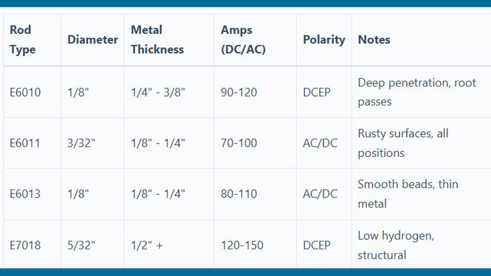
The ranges below are examples from named manufacturer guidance. They are starting points, not universal settings. The package for the electrode in your hand always takes priority.
| Example Electrode | Diameter | Example Range | Polarity |
|---|---|---|---|
| Lincoln Fleetweld 5P+ E6010 | 3/32 in. | 50–85A | DCEP |
| Lincoln Fleetweld 5P+ E6010 | 1/8 in. | 75–135A | DCEP |
| Lincoln Fleetweld 5P+ E6010 | 5/32 in. | 100–175A | DCEP |
| Lincoln Fleetweld 5P+ E6010 | 3/16 in. | 140–225A | DCEP |
| Lincoln Fleetweld 37 E6013 | 3/32 in. | 75–115A AC or 70–105A DC | AC or DC |
| Lincoln Fleetweld 37 E6013 | 1/8 in. | 110–140A AC or 100–135A DC | AC or DC |
| E7018 general manufacturer guidance | 3/32 in. | About 80–100A | Follow product label |
| E7018 general manufacturer guidance | 1/8 in. | About 90–150A | Follow product label |
| E7018 general manufacturer guidance | 5/32 in. | About 110–230A | Follow product label |
Run a test bead on scrap that matches the actual material and thickness. If the rod sticks and the bead sits high without fusing, add current in small steps. If the arc is violent, the rod overheats, or the toes wash away, reduce current or choose a more suitable diameter.
Electrode Storage and Moisture Control
Different electrode families need different storage conditions. Treating every rod like E7018 can damage cellulosic electrodes, while leaving low-hydrogen electrodes exposed can defeat their low-hydrogen classification.
- E7018 and other low-hydrogen electrodes: Keep sealed packages intact until needed. After opening, follow the manufacturer’s exposure limit and heated-storage instructions. Many products use a 250–300°F holding range.
- Reconditioning: A holding oven is not a reconditioning oven. Reconditioning uses a higher temperature and specified time. Follow the electrode manufacturer exactly.
- E6010 and E6011 cellulosic electrodes: Keep them dry as directed, but do not store them at high low-hydrogen holding temperatures unless the manufacturer specifically allows it. Their coating requires controlled moisture for proper arc performance.
- Damaged rods: Discard electrodes with flaking flux, rusted core wire, oil contamination, or handling changes after improper heating.
Machine Settings and Setup
Your welder’s front-panel amperage is only one part of the setup. A correct reading does not help if voltage is being lost through a poor input circuit, damaged lead, or weak connector.
- Input supply: Confirm the required 120V or 240V input, breaker, receptacle, and extension-cord size from the welder manual.
- Polarity: Connect the electrode holder and work lead exactly as required by the electrode.
- Amperage: Start in the manufacturer’s range for the exact diameter and adjust one variable at a time.
- Hot start: Use enough to establish the arc without creating a violent start or excess spatter.
- Arc force or dig: Add a small amount if the rod repeatedly sticks in a tight arc. Reduce it if the arc becomes harsh.
- Work clamp: Attach it to clean metal with firm jaw contact.
- Lead routing: Uncoil tightly bundled leads, protect them from sharp edges, and keep connections tight.
- Duty cycle: Stop when the machine reaches its rated operating limit or thermal protection activates.
Products Worth Considering

Heavy-Duty 8 Gauge Welder Extension Cord: Built with premium 100% pure copper 8AWG wires, this ETL Listed welder extension cord delivers up to 250V and 10000 watts of heavy-duty power. Featuring a secure NEMA 6-50 plug and receptacle (6-50P to 6-50R), it's the ideal heavy-duty welding extension cord 240v 25ft for powering MIG welders, TIG welders, Stick welders, and plasma cutters
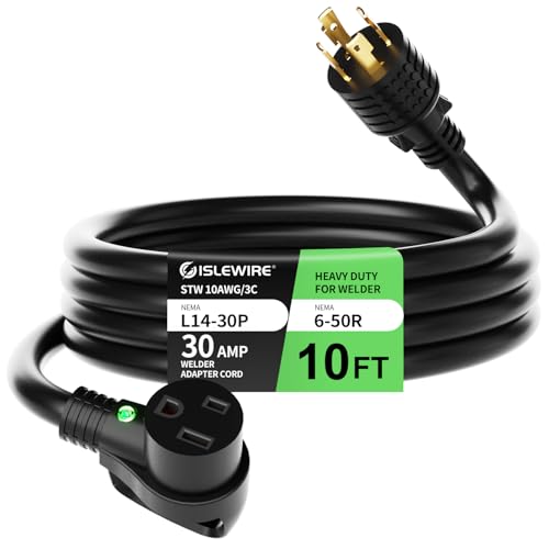
30 Amp Welder Adapter Extension Cord: Built with ETL Listed 10AWG 100% copper conductors, this NEMA L14-30P to 6-50R extension cord supports 30 Amps at 250 Volts, delivering up to 7,500 Watts of stable, high-load power. Designed to convert your 4-prong generator outlet into a 3-prong welder plug, it's the ideal welder adapter cord 30 amp for stick welders, MIG/TIG setups, and plasma cutters—no rewiring required.

Heavy-Duty 8 Gauge Welder Extension Cord: Built with premium 100% pure copper 8AWG wires, this ETL Listed welder extension cord delivers up to 250V and 7500 watts of heavy-duty power. Featuring a secure NEMA 6-50 plug and receptacle (6-50P to 6-50R), it's the ideal heavy-duty welding extension cord 240v 25ft for powering MIG welders, TIG welders, Stick welders, and plasma cutters.
Material-Specific Notes
Mild steel: E6010, E6011, E6013, and E7018 may all be useful, but they are not interchangeable. Choose by joint design, position, required strength, penetration, code, and power-source capability.
Stainless steel: Match the electrode to the stainless grade and service. Use clean tools reserved for stainless when contamination matters. Stainless welding can create hexavalent chromium in the fume, so ventilation and exposure control are especially important.
Cast iron: Identify whether the part is gray iron, ductile iron, or another casting. Nickel-based electrodes are common for repair, but joint preparation, bead length, peening, preheat, and cooling methods depend on the casting and procedure.
Aluminum: Stick welding aluminum is possible with covered electrodes such as E4043, but it is fast, smoky, and less forgiving than MIG or TIG. Common E4043 products specify DCEP rather than AC. Clean the oxide layer with a dedicated stainless-steel brush, use the polarity and amperage printed on the package, and verify that the base alloy is weldable. See the manufacturer information for an E4043 aluminum SMAW electrode.
Safety Considerations
Stick welding exposes the operator and nearby people to electric shock, ultraviolet and infrared radiation, hot metal, sparks, fire, fumes, gases, noise, and flying slag. OSHA’s welding hazards and solutions page provides an overview of these risks.
Essential PPE includes:
- A welding helmet with a filter shade selected for the electrode size and arc current
- Safety glasses with side protection under the helmet
- Dry leather welding gloves
- Flame-resistant clothing that covers the skin
- High-top leather or suitable safety boots
- Hearing protection when noise or flying slag requires it
OSHA’s filter-lens table lists minimum SMAW shades of 7 below 60 amps, 8 from 60–160 amps, 10 from 160–250 amps, and 11 from 250–550 amps. Use the darkest shade that still allows the work to be seen clearly, and follow the helmet manufacturer and applicable workplace rules.
Ventilation and fume control:
- Keep your head out of the plume.
- Use local exhaust close enough to capture fume before it crosses the breathing zone.
- Do not assume that an open door, a fan, or outdoor work automatically provides adequate control.
- Identify coatings and base-metal hazards before welding galvanized, painted, plated, stainless, lead-coated, or cadmium-bearing metal.
- Use a respirator only when it is correctly selected for the hazard and used under the applicable respiratory-protection requirements. It is not a substitute for proper ventilation.
Fire and electrical safety:
- Remove combustibles and protect openings where sparks can travel.
- Keep an appropriate fire extinguisher nearby and use a fire watch when required.
- Inspect the holder, work clamp, cables, and insulation before use.
- Keep gloves and clothing dry and avoid welding in wet conditions.
- Turn off or isolate the machine before repairing leads or changing internal connections.
- Never weld a sealed container or an improperly cleaned container that held a flammable or toxic material.
- Do not weld in a confined space without the required ventilation, atmospheric testing, entry controls, and rescue planning.
General workplace requirements are covered in OSHA 29 CFR 1910.252.
A smooth bead is encouraging, but it is not proof of complete fusion, correct penetration, or freedom from internal defects.
Step-by-Step Guide to a Clean Stick Weld
- Identify the material and job requirements. Confirm the metal type, thickness, joint, position, service, and whether a code or welding procedure applies.
- Inspect the equipment. Check the input supply, holder, work clamp, connectors, leads, and machine duty cycle.
- Prepare the joint. Remove oil, moisture, paint, rust, scale, coatings, and old slag. Bevel or gap the joint when required for root access.
- Select the electrode. Match classification, diameter, strength, position, polarity, penetration, and storage condition to the job.
- Set polarity and amperage. Use the package or data sheet, then start near the middle of the range.
- Clamp and tack the work. Check alignment, fit-up, root opening, and distortion control before completing the joint.
- Strike the arc. Use a scratch or tap start and immediately establish the required short arc.
- Control the puddle. Hold the correct work angle, use a small travel angle, feed the rod as it shortens, and keep the arc on the leading edge.
- Clean every pass. Chip, brush, and grind as needed before depositing more weld metal.
- Inspect and correct. Look for cracks, undercut, overlap, pores, irregular toes, and incomplete filling. Remove defects rather than covering them.
- Use required testing. Practice coupons may be cut, bent, or broken for learning. Critical production welds require the inspection or testing specified by the job.
Pro Tip: Practice stringer beads first. Once you can hold a steady arc length, angle, and speed without watching the slag, move to fillets, groove joints, and controlled weaves.
Conclusion
Stick welding rewards a methodical approach. When a bead goes wrong, resist the urge to change several controls at once. Start with the electrode label, clean the joint and work connection, verify polarity, set a diameter-appropriate current, and run a short test bead.
Porosity, arc blow, sticking, spatter, undercut, cracking, slag inclusions, poor fusion, burn-through, waviness, and distortion each leave useful clues. Learn to read those clues, correct one variable at a time, and remove defects instead of burying them. For structural or safety-critical work, use the approved procedure and required inspection rather than relying on appearance alone.
Frequently Asked Questions
Why does my electrode keep sticking?
The usual causes are low amperage, a hesitant start, poor work-clamp contact, excessive voltage loss in the leads or extension cord, damaged flux, or an electrode that is difficult for the machine to run. Verify the package settings, clean the connection, and increase current in small steps within the listed range.
How do I reduce spatter in stick welding?
Shorten the arc, lower excessive amperage, verify polarity, and check for arc blow or a weak work connection. Some electrodes naturally create more spatter than others, so compare the result with the manufacturer’s expected operating characteristics.
What is the best stick electrode for beginners?
E6013 is often beginner-friendly because many products start easily, run on AC or DC, and produce a smooth bead with relatively low penetration. E7018 is also valuable to learn but requires tighter arc control and proper low-hydrogen storage. Choose a rod that your machine can run and follow its package settings.
How do I prevent porosity in my welds?
Clean the joint to sound, dry metal; use dry, undamaged electrodes; keep a short arc; and clean starts, stops, tacks, and previous passes. Do not cover visible pores with another pass. Remove the defective metal and correct the contamination or technique problem first.
Can I stick weld aluminum?
Yes, with a covered aluminum electrode intended for SMAW and a weldable aluminum alloy. Common E4043 stick electrodes specify DCEP, not automatic AC operation. Clean the oxide layer with a dedicated stainless-steel brush and follow the exact polarity, current, position, and preparation instructions on the package. MIG or TIG is usually easier for controlled aluminum work.
Why does my stick weld have poor penetration?
Poor penetration commonly comes from low current, fast travel, an electrode with shallow penetration, or joint preparation that blocks access to the root. Correct the bevel, root opening, or root face before simply increasing amperage.
What causes slag inclusions?
Slag becomes trapped when a previous pass is not fully cleaned, the arc is too cold, the angle lets slag run ahead, the weave is too wide, or the sidewalls do not fuse. Chip and brush every pass, grind stubborn pockets, and keep the arc on the leading edge of the puddle.
How can I tell whether a stick weld is strong enough?
Visual inspection can find surface cracks, porosity, undercut, overlap, poor profile, and incomplete filling, but it cannot prove internal fusion or penetration. Practice coupons can be cut, bent, or broken for learning. Production and critical welds require the inspection or testing specified by the governing procedure or code.
Sources
- Miller Electric — Guidelines for Shielded Metal Arc Welding — SMAW technique, amperage selection, arc length, bead shape, and defect troubleshooting
- Lincoln Electric — How to Prevent Arc Blow — causes, symptoms, and corrective cable, direction, current, and AC measures
- Miller Electric — Stick Electrode Questions and Storage Guidance — low-hydrogen holding and reconditioning principles
- Hobart Brothers — E7018 Welding Rod Amperage — E7018 classification, diameter-based current ranges, and technique
- OSHA — Welding, Cutting, and Brazing Hazards and Solutions — electrical, radiation, burn, fume, and PPE hazards
- OSHA 29 CFR 1910.133 — Eye and Face Protection — minimum protective filter shades for shielded metal arc welding