TIG welding aluminum rewards clean preparation and steady control. Aluminum carries heat away quickly, develops a tough oxide film, and gives little visual warning before a thin edge collapses. The process becomes much easier when you identify the alloy, prepare the joint correctly, use suitable filler and tungsten, and treat every machine setting as a tested starting point rather than a universal rule.
This guide covers the complete shop workflow, from deciding whether the part should be welded to setting AC balance, forming the puddle, filling the crater, and diagnosing porosity or lack of fusion. Practice on matching scrap before working on the actual part, especially when the component carries a load or is difficult to replace.
Image by hobartbrothers
Quick Answer
For most aluminum TIG welding, use AC, 100% argon, a clean lanthanated or ceriated tungsten, and filler matched to the base alloys. Degrease first, brush away oxide with aluminum-only tools, start near 75% electrode negative on a modern inverter, keep a short arc, and adjust amperage with a foot or fingertip control.
Key Takeaways
- Identify the base alloy before choosing filler or attempting a structural repair.
- Use AC for normal shop TIG welding of aluminum, but check whether the balance control displays percent EN or percent EP.
- Clean oil before brushing oxide, and never use a brush, file, or abrasive that has touched steel.
- A pointed or slightly truncated lanthanated or ceriated tungsten is usually the best starting point on a modern inverter.
- Control drafts instead of trying to overcome them with excessive argon flow.
- A smooth bead is not proof of penetration, internal soundness, or structural strength.
At a Glance
| Time Required | About 30–60 minutes to prepare and weld a small practice joint; skill development takes repeated sessions |
| Difficulty | Intermediate; thin sheet and critical repairs are advanced work |
| Tools Needed | AC/DC TIG welder, torch control, argon, regulator or flowmeter, suitable tungsten, filler rod, dedicated stainless brush, solvent-safe wipes, clamps, PPE, and matching scrap |
| Cost | Common practice consumables may total roughly $30–$100 when the welder, torch, cylinder, and safety equipment are already available |
Warning: Do not use general how-to guidance to repair an aircraft component, wheel, suspension part, fuel or pressure vessel, vehicle frame, climbing device, marine structure, or other life-safety component. Unknown alloys, previous damage, heat treatment, joint design, and inspection requirements can make a repair unsafe even when the bead looks excellent.
Why TIG Welding Aluminum Is Different
Aluminum conducts heat far more quickly than steel. A cold part may require substantial current to start the puddle, yet the same joint can overheat a few inches later as heat builds in the work. This is why a remote amperage control is so useful: you can start hot, establish fusion quickly, and reduce current as the joint warms.
The surface oxide creates a second challenge. Aluminum melts at approximately 1,200°F, while aluminum oxide melts near 3,600–3,700°F. The electrode-positive portion of an AC cycle helps disrupt that oxide, but AC cleaning does not replace proper mechanical and solvent cleaning. Miller explains the relationship between the oxide layer, AC waveform, and cleaning action in its guide to TIG waveforms and controls.
AC cleaning helps break up aluminum oxide, but cleanliness, filler selection, fit-up, and heat control still determine whether the joint is sound.
Identify the Alloy Before You Weld
Look for a mill marking, drawing, material certificate, stamped alloy number, or reliable manufacturer information. Do not guess from color or appearance. Aluminum alloys that look alike can react very differently to welding.
- 1XXX and 3XXX series: Generally weldable, though filler choice still depends on the exact alloy and service.
- 5XXX series: Commonly welded, especially in marine and transportation work. The magnesium content affects filler selection and crack resistance.
- 6XXX series: Commonly welded with fillers such as 4043 or 5356, but welding reduces strength in the heat-affected zone of heat-treated tempers such as T6.
- 2XXX and 7XXX series: Many grades are crack-sensitive or lose too much performance when fusion welded. Some specific alloys and procedures are weldable, but they are not beginner material.
- Cast aluminum: Weldability varies with alloy, porosity, oil absorption, previous repairs, and casting quality.
Note: If the alloy cannot be identified, restrict the work to noncritical practice or obtain qualified technical guidance. Filler selection cannot correct an unsuitable or unknown base alloy.
Choose the Right TIG Welder
For ordinary manual TIG welding of aluminum, choose an AC/DC machine with enough output for the material thickness and mass. A small machine may weld thin sheet well but struggle to establish fusion on a large casting or thick plate because the surrounding material pulls heat away from the joint.
Useful controls include:
- AC balance: Changes the proportion of electrode-negative penetration time and electrode-positive cleaning time.
- AC frequency: Changes arc shape. Higher frequency usually narrows and focuses the arc; lower frequency produces a wider, softer arc.
- High-frequency start: Starts the arc without touching the tungsten to the work.
- Foot pedal or fingertip control: Allows current to be reduced as the work heats up and helps fill the crater at the end.
- Adjustable pre-flow and post-flow: Protects the start, puddle, hot tungsten, and cooling weld.
- Pulse: Can help establish a repeatable rhythm or manage average current when correctly adjusted, but it is not required for a sound aluminum weld.
A DC-only TIG machine is not the normal choice for a beginner welding aluminum. Specialized DCEN procedures with helium-rich shielding are used in some thick-section applications, but they require different technique and should not be treated as a substitute for a normal AC setup.
Products Worth Considering

【Born for Aluminum Welding】AC TIG mode is perfect for dealing with Aluminum and Aluminium alloy.
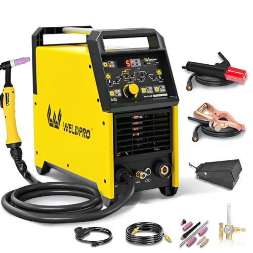
200A AC/DC TIG WELDER & 5 IN 1 MULTIPROCESS WELDING MACHINE: This versatile high frequency welder combines 5 welding modes in one portable design: High-Frequency AC TIG, DC TIG, AC Pulse TIG, DC Pulse TIG, and Stick MMA welding. Perfect for welders of all skill levels, from hobbyists doing home DIY projects to professional fabricators, this ac dc tig stick welder handles all your welding needs with consistent, reliable performance

POWERFUL 7-IN-1 TIG WELDER AC/DC: The Welder is capable of welding with DC TIG / DC Pulse TIG / AC TIG / AC Pulse TIG / AC Pulse TIG Square / AC Pulse TIG Triangular / STICK /SPOT TIG Methods. AC TIG is used in finesse welding various aluminum alloys, magnesium alloys, and other non-ferrous metals. DC TIG provides low-temperature control. You need precise welding for various types of steel: stainless steel, carbon steel, copper.
Select the Tungsten Electrode
The best electrode depends on the power source. Follow the machine manual when it conflicts with generic advice.
| Tungsten | Common Color | Best Use | Important Note |
|---|---|---|---|
| 2% lanthanated | Blue | Versatile AC and DC use on many inverter machines | A strong general starting choice |
| 1.5% lanthanated | Gold | AC and DC on many modern machines | Do not confuse it with blue 2% lanthanated |
| 2% ceriated | Gray | Low-to-moderate current AC or DC and reliable arc starting | Frequently recommended for inverter AC |
| Zirconiated | White | AC aluminum, especially where a rounded tip is specified | Good resistance to tungsten contamination or spitting |
| Pure tungsten | Green | Traditional transformer-machine AC practice | Usually not the first choice for a modern inverter |
Miller’s current tungsten selection guide explains the operating differences among these electrodes.
Products Worth Considering

BLUE-2% LANTHANATED: Lanthanated electrodes are popular due to the relative ease of striking an arc and lower amperage required. They perform exceptionally well in both AC and DC applications.
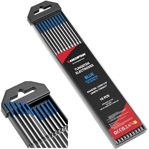
TOP QUALITY: This 10-pack of 2% Lanthanated tig tungsten electrodes 1/16"x7"(Blue, WL20/EWLa-2) adhere to Standard AWS A5.12M/A5.12:2009 and DIN EN 26848 GB/T 31908-201. All our tungsten has 100% traceability.

TOP QUALITY: This 10-pack of 2% Lanthanated tungsten electrodes 0.04"x7"(Blue, WL20/EWLa-2) adhere to Standard AWS A5.12M/A5.12:2009 and DIN EN 26848 GB/T 31908-201. All our tungsten has 100% traceability.
Prepare and Size the Tungsten
For a modern inverter or square-wave machine, grind lanthanated or ceriated tungsten lengthwise to a taper and leave a small flat at the tip. The end may round slightly after the arc starts. Do not intentionally form an oversized ball unless the power-source manual calls for it.
An older transformer machine may use pure or zirconiated tungsten with a rounded tip. Excessive balling, splitting, nodules, or rapid erosion usually indicates too much electrode-positive time, too much current for the electrode diameter, contamination, or incorrect preparation.
Common starting sizes are:
- 1/16 inch: Thin sheet and lower current.
- 3/32 inch: A versatile size for many small and medium shop jobs.
- 1/8 inch: Higher-current work and thicker sections.
Use a dedicated tungsten grinder or clean grinding wheel and grind parallel with the electrode. If the tungsten touches the puddle or filler rod, stop and regrind it. Continuing with contaminated tungsten makes the arc unstable and can place inclusions in the weld.
Choose the Correct Filler Rod
Filler selection is not based on base-metal strength alone. You also need to consider crack resistance, corrosion, ductility, anodized color, operating temperature, and the alloy on each side of the joint. Lincoln Electric’s aluminum TIG filler guide provides a broader alloy-matching chart.
| Filler | Common Uses | Advantages | Limits |
|---|---|---|---|
| 4043 | Many 6XXX alloys, including common 6061 applications, and many castings | Fluid puddle, smooth appearance, and relatively low crack sensitivity | Lower ductility and shear strength than 5356; poor color match after anodizing |
| 5356 | Many 5XXX alloys, 5052, and some 6XXX joints requiring higher shear strength or better anodized color | Higher strength and ductility than 4043 in many permitted combinations | Not normally selected for prolonged service above about 150°F unless the governing procedure permits it |
| 5183 or 5556 | Higher-strength 5XXX fabrication such as specified 5083 or 5086 work | Higher deposited strength where the design requires it | Must be selected from an approved chart, drawing, or WPS |
| 4047 | Certain castings, leak-sensitive joints, heat exchangers, and procedures that benefit from higher silicon | Very fluid and may reduce hot cracking in approved combinations | A specialized option, not a universal thin-sheet filler |
Keep 1/16-inch and 3/32-inch rods for common practice work, but choose rod size so it melts into the leading edge without chilling the puddle. Store filler in a clean, dry, covered container. Bring cold material and filler to shop temperature before opening the container so moisture does not condense on them.
Pro Tip: Label each filler container with its alloy and diameter. Bare aluminum rods can be difficult to distinguish after their original packaging is discarded.
Select Shielding Gas and Flow
Use 100% argon for most manual aluminum TIG welding. It starts easily, produces a stable AC arc, and works well on thin and medium material. Argon-helium mixtures can increase heat input on thick sections, but they alter starting, voltage, puddle behavior, and required flow.
A common indoor starting range is about 15–20 CFH with a suitable cup. Larger cups, unusual torch angles, high amperage, helium mixtures, or special joints may need a different flow. Verify flow at the torch rather than relying only on the regulator scale.
More flow is not always better. Excessive flow can become turbulent and draw room air into the shielding envelope. Keep the torch angle modest, shorten excessive electrode stickout, clean the gas lens, inspect O-rings and hoses, and shield the work from drafts.
Warning: Do not TIG weld in uncontrolled wind or a confined space. Argon can displace oxygen, and an ordinary shop fan can both disturb shielding and move contaminants through the breathing zone. Confined-space work requires atmospheric testing, ventilation, rescue planning, and trained personnel.
Clean and Prepare the Aluminum
Cleaning should remove hydrocarbons first and oxide second. Brushing an oily surface can drive contamination into the metal.
- Identify coatings and contamination. Remove paint, sealant, anodizing, adhesive, corrosion, and other material far enough from the joint to prevent contamination.
- Degrease. Use a manufacturer-approved nonchlorinated cleaner such as acetone or suitable isopropyl alcohol with a clean lint-free wipe. Follow the product safety data sheet.
- Allow the solvent to evaporate fully. Keep open solvent and used wipes away from the hot-work area.
- Remove oxide. Use a clean stainless steel wire brush dedicated to aluminum, a clean file, or a carbide tool appropriate for the joint.
- Prepare the edges. Remove smeared metal from saw cuts, deburr the joint, and bevel thicker material when the procedure requires full penetration.
- Check fit-up. Keep root opening, alignment, and contact consistent. Large uncontrolled gaps make thin aluminum difficult to weld.
- Clean the filler. Wipe visibly contaminated rod with a clean approved solvent wipe and allow it to dry.
- Weld soon after cleaning. Oxide begins forming again immediately, and exposed surfaces collect moisture and shop debris.
Warning: Never use chlorinated brake cleaner or allow chlorinated degreasing vapors near a welding arc. Heat and ultraviolet radiation can create highly toxic decomposition products. Do not use compressed shop air to dry the joint because it may add oil or moisture.
Plan the Joint, Backing, and Tacks
Thin butt joints need close, consistent fit-up. A large gap concentrates heat at the edges and increases burn-through. Lap and fillet joints require enough current to fuse the root rather than laying filler on the surface.
A clean copper or aluminum backing bar can support thin sheet and absorb heat. Do not use unknown plated or coated backing material. Clamp the parts so they cannot lift or pull out of alignment, but remember that rigid restraint can increase residual stress.
Place enough tacks to hold the fit without creating a row of oversized cold spots. The correct spacing depends on part size, thickness, stiffness, and expected distortion. Clean and feather defective or heavily oxidized tacks before welding over them.
Use Reliable Starting Settings
The following ranges are starting points for clean, flat-position groove welds with argon. They are not substitutes for the machine manual or a qualified welding procedure. Part mass, alloy, joint type, position, waveform, edge preparation, and travel speed can change the current substantially.
| Aluminum Thickness | Approximate AC Range | Typical Tungsten Starting Size | Comments |
|---|---|---|---|
| 1/16 inch | 70–100 amps | 1/16–3/32 inch | Use tight fit-up, quick puddle formation, and prompt travel |
| 3/32 inch | 95–115 amps | 3/32–1/8 inch | A comfortable practice thickness |
| 1/8 inch | 125–150 amps | 1/8 inch | The pedal may be set above the expected running current for fast starts |
| 3/16 inch | 170–190 amps | 5/32 inch or machine-approved equivalent | Edge preparation and multiple passes may be required |
| 1/4 inch | 220–275 amps | 3/16 inch or machine-approved equivalent | Confirm machine duty cycle, torch capacity, joint preparation, and cooling |
These values are consistent with the flat-position groove-weld ranges in the manufacturer’s Guide for Aluminum Welding. Test the complete setup on matching scrap and examine the root before welding the actual part.
Set AC Balance Correctly
First determine how the machine labels balance:
- Percent EN: A higher number means more electrode-negative time, generally giving more penetration and less cleaning.
- Percent EP or cleaning: A higher number means more electrode-positive time, giving more cleaning but also more heat on the tungsten.
On a modern machine that displays percent EN, start near 75% EN on clean material. If black pepper-like oxide remains in the puddle despite proper cleaning and gas coverage, reduce EN in small steps to add EP cleaning. Miller advises that if acceptable cleaning requires going below roughly 60% EN, the part often needs better mechanical cleaning rather than still more EP.
Too much EP can create a very wide etched zone, overheat or split the tungsten, produce a soft arc, and reduce useful penetration. Too little EP can leave oxide islands, peppering, and poor puddle wetting.
Set AC Frequency and Pulse
Start AC frequency around 100–120 Hz when the machine allows adjustment. Raise it when you need a narrower, more focused arc for a tight fillet or narrow joint. Lower it for a broader arc and wider bead. The available range and arc behavior vary by power source.
Pulse is optional. A low pulse rate around 1–2 pulses per second can provide an easy visual rhythm for adding filler. Higher pulse frequencies can change arc concentration and puddle response. Heat input depends on peak current, background current, pulse duty cycle, and travel speed together, so turning on pulse does not automatically prevent burn-through.
Pro Tip: Learn to make a clean bead without pulse first. Add pulse only when it solves a specific problem, such as timing filler additions or controlling average current on repeatable thin-sheet work.
Use Preheat Carefully
Most thin and medium shop work does not need preheat. A large casting or thick plate may benefit from uniform, measured preheat when the available machine cannot establish the puddle promptly.
Do not guess by color; aluminum gives little visible warning before melting. Use temperature crayons, a contact probe, or another suitable measuring method. Manufacturer procedure tables may permit optional preheat up to about 250°F in specific thick-section applications, but excessive temperature or prolonged heating can reduce the strength of heat-treated aluminum.
Never use preheat to burn oil out of a contaminated casting in an occupied shop. Oil-soaked or unknown castings may release hazardous fumes and may remain porous after repeated cleaning.
TIG Weld Aluminum Step by Step
- Confirm the material. Identify the alloy, temper, thickness, joint type, filler, and whether the work is noncritical.
- Inspect the equipment. Check torch parts, cooling, cables, work clamp, gas connections, cylinder security, and electrode condition.
- Prepare the joint. Degrease, remove oxide, deburr, bevel when needed, align, clamp, and tack.
- Set the machine. Select AC, suitable maximum current, the correct balance convention, appropriate frequency, high-frequency start, and adequate post-flow.
- Position the torch. Hold it roughly 10–15 degrees from vertical in the direction of travel. Keep the arc short, commonly around 1/16–1/8 inch depending on electrode size and access.
- Form the puddle quickly. Apply enough current to establish fusion without spending a long time heating the surface. Look for a bright, fluid puddle with clear movement at both joint edges.
- Add filler at the leading edge. Keep the rod inside the shielding envelope, withdraw it slightly between additions, and avoid touching the tungsten.
- Move steadily. Maintain arc length, torch angle, and filler rhythm. Reduce pedal pressure as heat accumulates.
- Fill the crater. Add a final small amount of filler while tapering current down. Do not snap the arc off while leaving a deep concave crater.
- Hold position during post-flow. Keep the torch over the cooling weld and tungsten until shielding stops.
The puddle should flow into both sides of the joint. A bead that sits high and narrow may be cold or may lack root fusion. Adding more filler does not correct a joint that has never fused.
Control Thin Aluminum Without Burn-Through
- Use close, even fit-up and remove burrs that create uneven edge thickness.
- Use a clean backing bar when the joint permits it.
- Set enough maximum amperage to create the puddle quickly, then control actual current with the pedal.
- Use a smaller filler rod so each addition does not chill the puddle excessively.
- Keep the arc short and avoid a steep forward torch angle.
- Move away from corners and free edges before heat builds.
- Alternate between distant areas when the joint design allows it.
- Stop and allow cooling rather than chasing an enlarging puddle with faster filler additions.
Troubleshoot Common Aluminum TIG Problems
| Problem | Likely Causes | Corrections |
|---|---|---|
| Porosity | Oil, moisture, hydrated oxide, leaking gas system, wind, long arc, contaminated filler, or turbulent flow | Clean and dry the joint, inspect hoses and torch seals, control drafts, verify flow, shorten the arc, and use clean filler |
| Black pepper or oxide in the puddle | Insufficient cleaning action, heavy oxide, poor precleaning, or inadequate shielding | Clean again, verify gas coverage, and add EP cleaning in small balance adjustments |
| Very wide frosted cleaning band | Excessive electrode-positive time, long arc, or slow travel | Increase percent EN, shorten the arc, and maintain suitable travel speed |
| Tungsten balls excessively or splits | Too much EP, too much current for the diameter, wrong electrode, or contamination | Increase EN, use a larger or suitable electrode, regrind, and check machine polarity and setup |
| Arc wander | Contaminated or poorly ground tungsten, excessive stickout, low frequency, poor work connection, or gas turbulence | Regrind lengthwise, shorten stickout, raise frequency if useful, secure the work clamp, and correct gas flow |
| Lack of fusion | Low current, slow puddle start, poor edge preparation, long arc, excessive filler, or fast travel | Increase available current, establish the puddle before adding filler, prepare the root, and test the joint cross-section |
| Burn-through | Wide gap, excess heat accumulation, long dwell, poor backing, or inconsistent edge thickness | Correct fit-up, use backing, reduce average current, shorten dwell, and move to cooler sections |
| Crater crack | Abrupt arc termination or a deep concave crater | Taper current down, add filler, and leave the crater slightly convex rather than hollow |
Inspect the Weld
Begin with a careful visual inspection under good light. Look for cracks, unfilled craters, undercut, overlap, excessive concavity, irregular width, surface porosity, oxide inclusions, and incomplete tie-in at the toes.
Do not judge quality by a “stack of dimes” pattern alone. A regular bead can still hide incomplete root fusion or internal porosity. For practice coupons, cut and etch a cross-section or perform an appropriate bend or break test. Production and code work may require liquid penetrant testing, radiography, ultrasonic examination, mechanical tests, or other inspection specified by the drawing or procedure.
TIG normally produces little or no spatter. If particles are present, identify their cause rather than automatically brushing the finished bead. Avoid aggressive cosmetic grinding on a structural weld unless the procedure permits it.
Understand Heat-Affected-Zone Strength
Welding changes the properties of aluminum near the joint. Heat-treated 6XXX material such as 6061-T6 can lose substantial strength in the weld-affected zone because the welding heat changes its temper. Some non-heat-treatable alloys also lose strength gained through cold work.
This means the filler rod is not the only strength consideration. Joint shape, base-metal temper, HAZ width, load direction, fatigue, weld size, and post-weld treatment all affect performance. Lincoln Electric discusses this design problem in its guide to common aluminum design mistakes.
Warning: Never assume that replacing a cracked weld with a larger bead restores the original strength. The crack may come from a design, fatigue, alloy, temper, fit-up, or loading problem that welding alone cannot correct.
Follow Essential Welding Safety
Wear an arc-rated welding helmet, safety glasses with side protection, flame-resistant clothing, dry welding gloves, and closed leather footwear. Select the filter shade according to the welding current, helmet instructions, and applicable workplace requirements. OSHA’s general guide lists shade 11 for gas-shielded nonferrous arc welding, but the correct setting still depends on the actual operation.
Use local exhaust or suitable general ventilation that removes contaminants without pulling shielding gas away from the weld. Welding on painted, coated, plated, oily, or unknown material may produce hazards very different from clean aluminum. Review the base-metal, filler-metal, and cleaning-product safety data sheets.
Secure shielding-gas cylinders upright with an approved chain or restraint. Protect the valve, use the correct regulator, inspect hoses, and close the cylinder when work is complete. Never lift a cylinder by its cap or expose it to welding current.
Remove combustible materials from the hot-work area, protect openings and the opposite side of walls or panels, keep a suitable extinguisher available, and continue checking for smoldering material after the job. Never weld a sealed container or a tank that previously held fuel, solvent, or another hazardous substance unless it has been professionally prepared under an approved hot-work procedure.
Follow the applicable requirements in OSHA 29 CFR 1910.252 or the corresponding rules for your location and type of workplace.
Pros and Cons of TIG Welding Aluminum
| Pros | Cons |
|---|---|
| Precise puddle and filler control | Steeper learning curve than many wire-feed processes |
| Well suited to thin material and visible work | Slower deposition than aluminum MIG |
| Little spatter and no flux slag | Very sensitive to contamination and drafts |
| Independent control of heat and filler addition | AC equipment, shielding gas, torch parts, and practice add cost |
| Can produce high-quality welds on many weldable alloys | Not every aluminum alloy or damaged component is suitable for TIG repair |
Real-World Applications
DIY and hobby projects: Toolboxes, brackets, noncritical racks, trim, and practice assemblies are good places to develop control. Start with clean 1/8-inch 6061 practice plate and filler selected from an alloy chart. Cut some coupons apart so you learn what fusion looks like below the surface.
Thin sheet work: Panels, tanks, and formed components demand close fit-up, clean edges, suitable backing, and fast response with the amperage control. Leak-tight appearance does not guarantee structural or pressure integrity.
Marine and transportation fabrication: Alloy identification, filler selection, corrosion exposure, fatigue, and inspection become more important. Follow the drawing and qualified procedure rather than using a generic 4043 or 5356 recommendation.
Aerospace and other regulated work: Welding must follow approved materials, procedures, welder qualifications, inspection requirements, and repair data. General practice guidance is not an acceptable replacement.
Student training: Begin with bead-on-plate exercises before butt and fillet joints. Keep a setup log listing alloy, thickness, filler, tungsten, current, balance, frequency, cup, flow, and result. That record makes improvement much faster than changing several controls at once.
Industry Standards and Codes
Structural aluminum work in the United States may be governed by AWS D1.2/D1.2M when that code is named in the contract documents. In May 2026, the American Welding Society announced a 2026 revision intended to update the 2014 edition later in the year. Confirm which edition the engineer, owner, authority having jurisdiction, or contract requires rather than assuming the newest or oldest edition automatically applies. See the AWS announcement for the AWS D1.2/D1.2M:2026 structural aluminum code.
ASME Boiler and Pressure Vessel Code Section IX contains rules for qualifying welding procedures, welders, brazers, and related personnel. It does not by itself provide every design, fabrication, examination, and acceptance rule for a pressure vessel. The governing construction code, project specification, jurisdiction, and qualified WPS must be followed together.
Code work may control base and filler classifications, joint details, preheat and interpass temperature, essential variables, welder qualification, inspection, repair methods, and documentation. A generic settings chart cannot replace those requirements.
Conclusion
Successful aluminum TIG welding starts before the arc. Identify the alloy, decide whether the component is appropriate for repair, select filler from a reliable chart, and clean hydrocarbons before removing oxide. On a modern inverter, a lanthanated or ceriated tungsten, roughly 75% EN balance, 100% argon, a short arc, and responsive amperage control form a reliable baseline.
From there, test one variable at a time on matching scrap. Watch the root as closely as the face, fill the crater, protect the cooling tungsten, and remember that appearance cannot prove structural strength. Careful preparation and repeatable testing will improve aluminum welds faster than chasing a perfect-looking bead with random machine adjustments.
Frequently Asked Questions
Is TIG better than MIG for welding aluminum?
Neither process is always better. TIG offers precise heat and filler control, making it useful for thin material, detailed work, and visible joints. Aluminum MIG is faster and often better for production or thicker fabrication. Either process can produce a sound weld when the procedure, preparation, and operator skill are suitable.
What is the best filler rod for TIG welding aluminum?
There is no universal filler. ER4043 is common for many 6XXX alloys and offers a fluid, crack-resistant puddle. ER5356 is common for many 5XXX alloys and some 6XXX joints needing higher shear strength or a better anodized color match. Critical work requires a filler chart or approved WPS based on both base alloys and service conditions.
How do I avoid burn-through on thin aluminum?
Use close fit-up, clean edges, a suitable backing bar, a short arc, and a foot or fingertip current control. Establish the puddle quickly, begin moving promptly, and reduce current as heat builds. Pulse can help in a tested setup, but fit-up and average heat input matter more than simply turning pulse on.
Can AC cleaning replace brushing the oxide layer?
No. AC cleaning helps disrupt the thin oxide film at the arc, but it does not remove oil, moisture, heavy corrosion, embedded debris, paint, or thick hydrated oxide. Degrease first, allow the solvent to evaporate, then use clean aluminum-only tools to remove oxide.
What AC balance should I use for TIG welding aluminum?
On a modern machine displaying percent electrode negative, about 75% EN is a useful starting point for clean aluminum. Reduce EN slightly when more oxide cleaning is genuinely needed. If the machine displays percent EP or cleaning instead, the numbers work in the opposite direction, so check the manual before adjusting.
Should aluminum TIG tungsten be pointed or balled?
Modern inverter and square-wave machines commonly use lanthanated or ceriated tungsten ground to a taper with a small flat. The tip may round slightly during AC welding. Older transformer machines may specify pure or zirconiated tungsten with a rounded tip. Follow the power-source manual rather than applying one preparation to every machine.
Can I safely repair a cracked 6061-T6 frame by TIG welding it?
Not from generic instructions alone. Welding changes the T6 temper and reduces strength in the heat-affected zone. A frame crack may also indicate fatigue, poor design, overload, or previous damage. Load-bearing frames require approved repair data, engineering evaluation, suitable filler, controlled procedure, and any required inspection or post-weld treatment.
Sources
- Miller — Guide to TIG Welding Basics — gas flow, tungsten preparation, AC balance, frequency, arc stability, and troubleshooting.
- Miller — AC Balance Control for Aluminum TIG Welding — percent-EN starting points and the relationship between cleaning and tungsten heating.
- Hobart/Miller — Guide for Aluminum Welding — cleaning, filler selection, shielding gas, preheat limits, and example TIG parameters.
- Lincoln Electric — TIG Welding Aluminum — base-alloy and filler-metal selection guidance.
- OSHA 29 CFR 1910.252 — arc-welding eye protection, clothing, ventilation, hot-work, cleaning-compound, and confined-space requirements.
- American Welding Society — AWS D1.2/D1.2M:2026 Preview — status of the announced structural aluminum code revision.