Getting clean results while TIG welding different thickness metals comes down to controlling where the arc puts its heat. The thinner part reaches its melting point first, while the thicker part pulls heat away from the joint. Your job is to establish the puddle mainly on the thicker member, wash it toward the thinner edge, add the correct filler, and move before the thin metal overheats.
The numbers in this guide are practical starting points, not certified welding procedures. Your final settings must account for the base alloy, joint design, welding position, machine waveform, fit-up, thermal mass, and service requirements. Test the full joint on matching scrap before welding the finished part.
Quick Answer
To TIG weld metals of different thicknesses, aim most of the arc at the thicker piece until a small puddle forms. Then move the puddle to the joint and briefly wash it onto the thin edge. Use tight fit-up, a short arc, suitable filler, fast travel, and pedal or fingertip amperage control.
Photo by fb/Aluminum Tig welding
Key Takeaways
- Choose settings by alloy, joint type, position, and thermal mass, not thickness alone.
- Start the puddle on the thicker piece and spend as little arc time as possible on the thin edge.
- Use a short arc, tight fit-up, small filler rod, backing bar, and controlled travel to reduce burn-through.
- Select tungsten by welding amperage rather than directly by the thickness of the workpiece.
- Do not use one universal preheat, pulse, AC-balance, or interpass-temperature setting.
- Follow a qualified WPS, applicable code, engineering instructions, or OEM repair procedure for critical work.
At a Glance
| Time Required | About 20–60 minutes for setup and practice, plus the welding time required by the joint |
| Difficulty | Intermediate; advanced for very thin sheet, large thickness differences, or code work |
| Tools Needed | Suitable AC/DC or DC TIG welder, torch control or pedal, argon regulator, torch, tungsten, filler rod, clamps, cleaning tools, PPE, and optional backing bar |
| Cost | Low to moderate for consumables when you already own the welder; cylinder, gas, filler, tungsten, and preparation costs vary by project |
Warning: TIG welding exposes you to ultraviolet radiation, hot metal, electric shock, fire, fumes, and compressed-gas hazards. Argon can displace oxygen in an enclosed space. Remove or control combustible materials, use suitable ventilation and PPE, secure the gas cylinder upright, and never weld a used tank, drum, fuel container, or closed cavity unless it has been made safe under an approved hot-work procedure. Do not perform structural, pressure, vehicle-safety, or other critical welding without the required qualifications and procedure.
TIG Welding Basics for Different Thicknesses
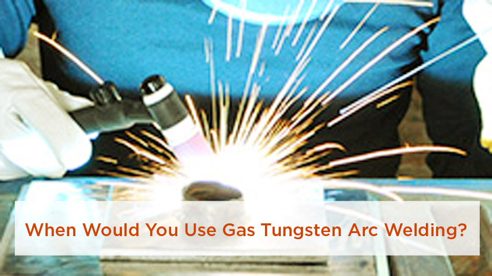
TIG, technically called gas tungsten arc welding or GTAW, uses a nonconsumable tungsten electrode to create the arc. An inert shielding gas, normally argon, protects the tungsten and molten weld pool from the surrounding atmosphere. You can make an autogenous weld without filler or feed a separate filler rod into the leading edge of the puddle.
The process works well on mild steel, stainless steel, aluminum, chromoly, nickel alloys, and many other metals. Its main advantage on mixed-thickness joints is independent control of the arc and filler. A foot pedal, fingertip control, or programmed upslope lets you add heat quickly and reduce it as the joint becomes hot.
Thickness alone does not determine your setup. A narrow strip of 1/4-inch steel attached to a large plate may respond differently from two small pieces of the same nominal thickness. Aluminum also carries heat away from the joint faster than steel, while stainless steel tends to hold heat near the weld and distort easily.
On a mixed-thickness joint, control the puddle on the thick member and let the puddle fuse the thin edge. Do not park the arc directly on the thin metal while waiting for the thick side to melt.
What Determines the Correct TIG Settings?
Before touching the machine controls, identify the variables that change the amount and location of heat you need:
- Base-metal alloy: Mild steel, stainless steel, and aluminum transfer and retain heat differently.
- Actual thickness: Measure both members instead of relying on appearance or sheet-gauge memory.
- Thermal mass: A large bracket, tube, frame, casting, or plate can pull heat away from a small joint.
- Joint geometry: Fillet, lap, butt, edge, and corner joints expose different amounts of metal to the arc.
- Welding position: Vertical and overhead welds often need a smaller, more controllable puddle than flat-position welds.
- Fit-up and root opening: A gap concentrates heat at unsupported edges and raises the risk of burn-through.
- Machine design: AC balance, AC frequency, pulse terminology, output at low amperage, and displayed percentages vary among power sources.
- Service conditions: Structural loads, corrosion, fatigue, pressure, temperature, and post-weld finishing affect filler and procedure selection.
Note: A visually smooth bead does not prove that the root fused or that the joint has adequate strength. Critical welds require the inspection and testing specified by the drawing, code, OEM procedure, or welding procedure specification.
Preparing the Metal and Workspace
Confirm the Base Metals
Do not choose filler or polarity until you know what you are welding. Confirm whether the parts are carbon steel, stainless steel, aluminum, chromoly, coated steel, or another alloy. A magnet, spark test, or appearance can provide clues, but it may not identify the exact grade. Use material markings, drawings, supplier records, or a verified material test when the grade affects safety or corrosion resistance.
Joining different thicknesses of the same alloy is not the same as joining two dissimilar alloys. A stainless-to-carbon-steel joint or one aluminum series joined to another may require a filler selected for dilution, strength, cracking resistance, and service conditions.
Clean Both Sides of the Joint
Remove oil, grease, moisture, paint, rust, scale, oxide, marker residue, plating, and cutting contamination. Degrease before abrasive cleaning so you do not grind oil into the surface. Use a clean abrasive or wire brush reserved for the material.
For aluminum, mechanically remove the oxide with a dedicated stainless-steel brush after degreasing. Brush shortly before welding because aluminum oxide reforms on the surface. Do not use a carbon-steel brush that can embed iron and cause contamination.
For stainless steel, use dedicated stainless abrasives and brushes. Keep carbon-steel grinding dust away from the joint and any surface that must remain corrosion resistant.
Improve Fit-Up
Thin sheet needs tight and consistent fit-up. A gap that looks small on 1/4-inch plate may be large compared with a 22- or 24-gauge edge. Trim and clamp the parts so the thin member is fully supported and the joint does not open as the tacks shrink.
If the thick member requires penetration beyond what you can obtain without overheating the thin side, bevel the thick edge while leaving the thin edge square. The bevel gives the arc access to the thick member and creates space for filler without unnecessarily thinning the weaker piece.
Use a Backing or Chill Bar When Appropriate
A clean copper backing bar can support thin steel or stainless sheet, draw heat away from the root, and make a small opening easier to bridge. Aluminum backing can also work in suitable applications. Clamp the bar tightly against the back of the joint and keep it free from oil and debris.
A backing bar changes cooling and penetration, so do not add one to a qualified joint unless the procedure allows it.
Selecting the TIG Welder and Torch
For steel and stainless steel, a DC TIG machine with stable low-amperage output may be enough. Conventional shop welding of aluminum normally requires an AC-capable TIG machine. An AC/DC inverter gives you additional control over AC balance, frequency, pulse, starting current, and downslope.
A machine rated around 200–230 amps can cover a wide range of hobby and light-fabrication work, but its maximum practical thickness depends on the input circuit, duty cycle, joint design, material, preheat allowed by the procedure, and whether you use one pass or several. Check the manufacturer’s duty-cycle chart rather than assuming the machine can hold its maximum output continuously.
A foot pedal is useful when the thick part needs a strong initial heat input but the thin edge needs less current. A fingertip control can offer similar adjustment when the position makes a pedal impractical.
Air-cooled torches are convenient for shorter, lower-amperage welds. A correctly sized water-cooled torch reduces operator heat and improves comfort during long, high-amperage sessions. Do not exceed the torch’s rating.
Products Worth Considering

【Born for Aluminum Welding】AC TIG mode is perfect for dealing with Aluminum and Aluminium alloy.

POWERFUL 7-IN-1 TIG WELDER AC/DC: The Welder is capable of welding with DC TIG / DC Pulse TIG / AC TIG / AC Pulse TIG / AC Pulse TIG Square / AC Pulse TIG Triangular / STICK /SPOT TIG Methods. AC TIG is used in finesse welding various aluminum alloys, magnesium alloys, and other non-ferrous metals. DC TIG provides low-temperature control. You need precise welding for various types of steel: stainless steel, carbon steel, copper.

Large LED Display: Features a large LED screen for enhanced visibility and a clear display of welding parameters and settings. Its intuitive interface ensures effortless operation, enabling precise welding of diverse metals
Choose Tungsten by Amperage
Tungsten diameter should follow the expected welding current, arc-starting needs, polarity, and machine guidance. It should not be chosen only from the thickness of the base metal.
| Tungsten Diameter | Approximate Working Range | Typical Use |
|---|---|---|
| 0.020 inch | About 5–20 amps | Extremely light-gauge and micro-TIG work |
| 0.040 inch | About 15–80 amps | Thin sheet and low-current precision work |
| 1/16 inch | About 70–150 amps | Light and medium fabrication |
| 3/32 inch | About 150–250 amps DCEN; approximately 140–235 amps AC | General fabrication and higher-current work |
| 1/8 inch | About 250–400 amps DCEN; approximately 225–325 amps AC | High-current, heavy-section work with a suitable torch |
These ranges are guides rather than hard changeover points. Your electrode alloy, tip preparation, shielding gas, AC balance, and torch cooling affect its capacity. A 1/16-inch or 3/32-inch electrode may also operate below the listed range on equipment that starts and controls the arc well.
Two-percent lanthanated or ceriated tungsten is a practical choice for many AC and DC applications. Follow the electrode manufacturer’s color identification because color conventions and product types must be verified from the package.
Prepare the Tungsten Correctly
For DCEN steel and stainless welding, grind the electrode lengthwise on a dedicated wheel. A fine point gives a narrow arc at low current, while a small flat or truncated point helps the tip carry more current without breaking down.
Do not automatically ball the tungsten for AC aluminum. Older transformer machines may use a rounded pure-tungsten tip, but modern inverter machines commonly perform better with ceriated or lanthanated tungsten ground to a pointed or truncated shape. Follow the power-source manual.
Regrind the tungsten if it touches the puddle or filler. Grinding only the visible contaminated end may leave contamination farther up the electrode, so remove enough material to reach clean tungsten.
Pro Tip: Keep prepared tungstens in a clean, labeled container. Separate electrodes used on aluminum, stainless steel, and carbon steel so shop contamination does not travel from one job to another.
Choosing the Filler Rod
Filler selection begins with the exact base-metal grade and the joint’s required properties. Diameter affects how much heat the rod removes from the puddle and how much metal each addition deposits. On thin material, a small rod is easier to melt without overheating the base metal. On a larger groove, a rod that is too small may require excessive feeding and arc time.
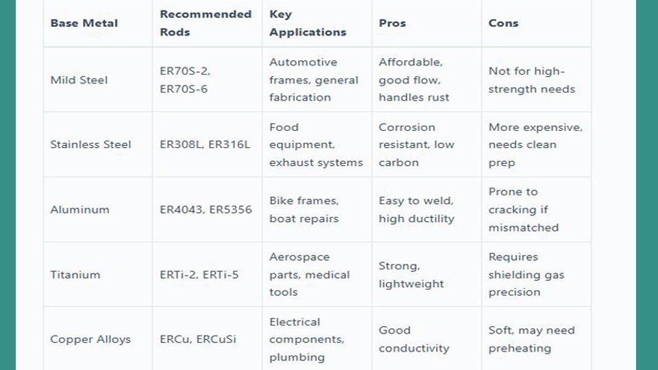
The following choices are common starting points, not substitutes for the filler manufacturer’s data or an approved procedure:
| Base Metal | Common TIG Filler | Selection Note |
|---|---|---|
| Mild or low-carbon steel | ER70S-2; ER70S-6 in suitable applications | Verify strength, cleanliness, coating, and procedure requirements. |
| 304 or 304L stainless steel | ER308L is common | Confirm the actual base grade and corrosion service. |
| 316 or 316L stainless steel | ER316L is common | Do not substitute ER308L merely because both parts look like stainless steel. |
| Common weldable aluminum alloys | ER4043, ER4943, or ER5356, depending on the alloys and service | Consider strength, crack sensitivity, anodizing color, corrosion, and service temperature. |
| Dissimilar metal or unknown alloy | Procedure-specific | Do not guess. Identify the materials and obtain qualified guidance. |
For a complete overview of common rod classifications, see the TIG welding filler rod selection chart. Always confirm the rod label before starting. Similar-looking bare rods are easy to mix up once they are removed from their original container.
Products Worth Considering

er308l stainless steel tig welding rods 1 16 x 16 1 6mm tig filler rod thin stainless sheet tubing handrail kitchen equipment low splatter corrosion resistant stainless steel welding wire tig welding accessories gta w argon arc

ER70S-6 TIG WELDING ROD: The main alloying elements of ER70S - 6 welding wire are C, Mn, Si, etc. Moderate carbon content ensures weld strength. Mn and Si, as deoxidizers and alloying elements, enhance weld's mechanical properties, crack resistance, toughness and strength

ER308L TIG WELDING ROD: ER308L is a low -carbon stainless steel tig welding rod, which has excellent anti -crystal interval corrosion properties and full -location welding performance.
Shielding Gas and Flow
Pure argon is the standard starting gas for most manual TIG welding. Argon-helium mixtures can increase arc voltage and heat input for some thick or highly conductive materials, but they also change starting behavior, required flow, cost, and technique.
A typical argon range is roughly 10–25 cubic feet per hour, but the correct setting depends on the cup diameter, gas lens, tungsten extension, joint shape, drafts, torch angle, and distance from the work. Increasing flow does not always improve protection. Excessive flow can become turbulent and draw surrounding air into the shielding envelope.
Use a gas lens when you need smoother coverage, a larger shielding area, or additional tungsten extension. Block fans and drafts instead of trying to overpower them with excessive gas flow.
Set post-flow long enough to protect the hot tungsten and weld end while they cool. Manufacturer guidance commonly falls around 10–15 seconds for general work, but the required time changes with current, electrode size, torch, and material. Keep the torch in place until the weld end is protected and the tungsten no longer glows.
Starting TIG Settings by Thickness
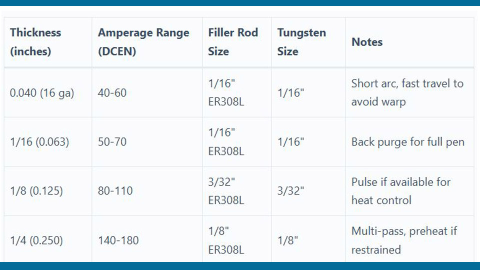
The table below gives conservative setup zones for practice coupons in the flat position. Treat the amperage as the machine’s available maximum when using a pedal, not as a requirement to hold full pedal throughout the weld.
| Material and Thickness | Starting Maximum Amperage | Tungsten Starting Point | Technique Note |
|---|---|---|---|
| 22–24 gauge mild steel or stainless | About 20–40 amps DCEN | 0.020 or 0.040 inch | Tight fit-up, short arc, small filler, backing bar, and short welds |
| 18–16 gauge mild steel or stainless | About 40–80 amps DCEN | 0.040 or 1/16 inch | Use fast travel and reduce pedal as the part heats |
| 1/8-inch mild steel or stainless | About 90–140 amps DCEN | 1/16 inch, with 3/32 inch where the current and procedure support it | Joint geometry may require beveling or more than one pass |
| 1/4-inch mild steel | About 150–220 amps DCEN | 3/32 inch | Bevel and multi-pass welding may be required; verify machine duty cycle |
| 1/16-inch aluminum | About 60–100 amps AC | 0.040 or 1/16 inch | Apply heat promptly, establish the puddle, and travel before heat spreads |
| 1/8-inch aluminum | About 90–140 amps AC | 1/16 or 3/32 inch | Start with the machine’s default AC balance and adjust only as needed |
| 1/4-inch aluminum | About 180–250 amps AC | 3/32 inch or larger as required by current | Machine capacity, joint design, helium addition, and approved preheat can change the requirement |
Use these ranges only to reach a controllable puddle on test material. Reduce current if the thin edge collapses before the thick member wets in. Increase current, improve the bevel, reduce the thick member’s heat sink when permitted, or change the process if the thick side never reaches fusion.
TIG Welding Thin Metal
Thin sheet requires a concentrated arc and minimal time at temperature. Keep the tungsten close to the work without touching it. A long arc spreads heat, raises voltage, weakens shielding, and makes the puddle harder to control.
Hold the torch about 5–15 degrees from vertical in the direction of travel. Excessive torch angle lengthens the arc and pushes the shielding gas away from the puddle. Move in a straight line rather than making a wide weave.
Thin-Metal Technique
- Clean both sides of the joint and confirm tight fit-up.
- Clamp the part to a flat fixture or clean backing bar when the joint allows it.
- Place small tacks at short, even intervals.
- Start at a tack or supported edge rather than an open gap.
- Establish a small puddle quickly and begin moving.
- Add a small amount of filler at the leading edge only when needed.
- Use short segments or a skip sequence to spread heat across the part.
- Reduce pedal pressure as the panel becomes heat soaked.
- Fill the final crater before extinguishing the arc.
Using Pulse on Thin Metal
Pulse can help, but there is no universal 50- or 100-PPS formula. At a low frequency such as roughly 0.5–2 pulses per second, the pulse can provide a visible rhythm for moving and adding filler. At higher frequencies, the rapid switching can stiffen the arc and reduce average heat at a chosen peak setting.
Peak amperage, background amperage, pulse frequency, and peak-time percentage interact. Begin with the machine manufacturer’s recommended thin-metal setup and change one control at a time. A poor fit-up will not be repaired by pulse settings.
What to Do If a Hole Starts
Release the control and stop the arc. Let the area cool, clean any oxidized edge, and clamp a copper backing bar behind the opening when possible. Begin on sound metal beside the hole, form a small deposit, stop, and repeat from another side until the opening is supported. Then blend the deposits with a short final pass.
Trying to hold the arc over the unsupported center while feeding more filler often makes the opening larger.
TIG Welding Medium-Thickness Metal
Material from about 1/16 to 1/4 inch is generally easier to control than very thin sheet, but the required heat still changes with alloy and joint design. Use enough available amperage to form the puddle promptly. Heating the joint slowly with an undersized arc can spread more total heat into the work and increase distortion.
For a fillet weld, point the arc toward the heavier member and the root. Confirm that both toes wet in before moving forward. Keep filler additions consistent so the bead does not become oversized.
A butt joint may require a bevel, root opening, or multiple passes. Do not rely on a wide cap to hide an unfused root. Clean the joint and inspect each pass before adding the next one.
Joint Preparation for Medium Stock
- Remove scale and oxide far enough from the joint to keep the puddle clean.
- Bevel the thick member when the arc cannot reach the required root without overheating the thin member.
- Keep the thin member square unless the procedure specifically calls for a bevel.
- Use enough tacks to hold alignment, but do not make oversized tacks that interfere with the root.
- Feather or blend tack ends if the weld must pass through them.
- Confirm that clamps will not trap excessive shrinkage or pull the joint out of alignment.
TIG Welding Thick Metal
On thick sections, TIG is slower than MIG, flux-cored, or stick welding because it deposits filler separately. TIG may still be selected for clean root passes, high-quality alloy work, precise repairs, or applications that require excellent puddle control.
Thick joints commonly need a bevel and several passes. The root opening, bevel angle, land, backing, purge, filler, preheat, and interpass limits must come from the drawing or welding procedure when the weld is critical.
Multi-Pass Strategy
- Prepare the groove to the required angle, root face, and root opening.
- Clean the groove and at least several inches of adjacent metal.
- Make the root pass using the qualified technique and filler.
- Inspect the root before covering it.
- Remove oxide, contamination, high spots, or defects between passes using tools approved for the material.
- Place fill beads so each bead fuses into the previous bead and groove wall.
- Control interpass temperature according to the WPS or material instructions.
- Apply the cap without excessive reinforcement or undercut.
- Complete the required visual or nondestructive inspection.
Walking the cup can be useful on some pipe and groove welds, but it is not required for every thick joint. The cup size, joint access, procedure, and workplace rules determine whether that technique is suitable.
Note: Do not apply a universal 200°F preheat or 300°F interpass limit. Some materials need preheat, some restrict it, and others require tightly controlled temperature ranges. Follow the material specification and WPS.
How to TIG Weld Thin Metal to Thick Metal
The safest approach is to use the thick member as the heat reservoir. Form most of the puddle there, then let the edge of that puddle fuse the thin part. The arc should spend more time on the thick metal, but the weld still needs visible wetting into both members.
Step-by-Step Thin-to-Thick Procedure
- Identify both materials. Confirm that they can be welded together and select the correct polarity, filler, and shielding gas.
- Measure both thicknesses. Use the actual dimensions to choose your initial current range and tungsten.
- Choose the joint. A lap or fillet joint may provide more support than an unsupported thin butt edge.
- Prepare the thick member. Add a bevel or small chamfer when it helps the arc reach the root without thinning the light member.
- Clean the joint. Remove coatings, oxide, oil, and scale from both sides and from the filler rod.
- Clamp tightly. Support the thin part and use a backing bar when the joint and procedure permit it.
- Set enough maximum current for the thick side. Use the pedal or torch control to deliver only the current the puddle needs.
- Make small tacks. Each tack must fuse both pieces. Start the arc on the thick side and wash the puddle into the thin edge.
- Test the tack sequence. Check that shrinkage is not opening the joint or lifting the thin member.
- Start the weld on the thick member. Hold a short arc and form a small puddle close to the joint.
- Move the puddle to the joint. Briefly wash the arc or puddle onto the thin edge instead of holding the arc directly over it.
- Add filler at the leading edge. Use small, consistent additions that do not chill the puddle excessively.
- Travel promptly. Move as soon as both toes fuse. Back off the pedal as the thick member becomes hot.
- Use short sections when needed. Skip around the part to distribute heat and allow cooling.
- Fill the crater. Reduce current gradually while adding enough filler to avoid a concave crater.
- Inspect the joint. Look for complete wetting, undercut, burn-through, overlap, porosity, cracks, and missed edges.
Pro Tip: Practice with offcuts that match the final part in alloy, thickness, orientation, backing, and joint shape. A bead laid on flat scrap will not predict how a thin bracket behaves when attached to a large frame.
Material-Specific Adjustments
Mild Steel
Use DCEN for ordinary TIG welding of mild steel. Remove mill scale near the joint because scale can destabilize the puddle and trap contamination. ER70S-2 is a common TIG filler, while other classifications may be required by the base metal or procedure.
Steel often gives a clear visual puddle, making it a good material for practicing thin-to-thick control. Watch the thin edge carefully. It may round and collapse before the thicker member appears fully fluid.
Stainless Steel
Stainless steel holds heat near the weld, so use a short arc, quick travel, restrained bead size, and a planned tack sequence. Excessive heat can increase distortion and discoloration and may reduce corrosion performance.
Match filler to the grade. ER308L is common for many 304-series joints, while ER316L is common for 316L. A dissimilar stainless-to-carbon-steel joint may need another filler selected for dilution and service.
Back purging protects the root of a full-penetration stainless tube or pipe weld from heavy oxidation, often called sugaring. It is not automatically required for every stainless fillet or sheet-metal joint. Use it when the root surface, corrosion service, procedure, or specification requires it.
Aluminum
Use AC for conventional shop TIG welding of aluminum unless a qualified procedure specifies another method. Clean the metal thoroughly and use a suitable ceriated or lanthanated tungsten preparation for your machine.
Begin with the power source’s default AC balance on clean material. Increase cleaning action only when the oxide condition requires it. Too much electrode-positive time puts additional heat into the tungsten and reduces penetration.
Higher AC frequency generally creates a narrower, more focused arc on machines with adjustable frequency. That can help aim heat at a small joint or thin-to-thick transition, but it is not automatically the right setting for every thin aluminum weld.
Aluminum may seem slow to form a puddle and then become fluid quickly. Apply adequate heat, watch for the surface to turn shiny, add filler, and move. Lingering with low current can heat a large area and increase distortion.
Pros and Cons of TIG for Mixed Thicknesses
| Aspect | Advantages | Limitations |
|---|---|---|
| Heat Control | Pedal, fingertip, pulse, upslope, and downslope controls can respond to changing thermal conditions. | The operator must coordinate the torch, current, travel, and filler accurately. |
| Weld Quality | Clean process with precise bead placement and little spatter. | A clean-looking surface can still hide incomplete root fusion. |
| Versatility | Suitable for steel, stainless, aluminum, and many specialty alloys. | Different alloys require different polarity, filler, cleaning, and shielding practices. |
| Productivity | Excellent for roots, detailed work, and small precision joints. | Slow filler deposition makes large thick joints time-consuming. |
| Consumables | Separate filler control can reduce unnecessary buildup. | Shielding gas, tungsten preparation, torch parts, and dedicated cleaning tools add cost and setup time. |
Common Mistakes
- Setting current only for the thin piece: The thick side never reaches fusion, so the bead sits on its surface.
- Holding the arc on the thin edge: The edge melts away while the thick member remains cold.
- Using a long arc: Heat spreads, shielding weakens, and the puddle becomes harder to direct.
- Using oversized filler on thin sheet: The rod chills the puddle and requires extra arc time to melt.
- Using undersized filler on a large groove: The welder spends too long feeding enough metal into the joint.
- Using the wrong tungsten preparation: The arc wanders or the tip breaks down at the selected current.
- Trying to solve poor shielding with excessive flow: Turbulence can pull air into the gas envelope.
- Ignoring heat buildup: A setting that works at the start may be too hot near the end of a long seam.
- Failing to fill the crater: A concave crater can develop a centerline crack.
- Covering a defective root: Additional passes hide rather than repair lack of fusion, porosity, or contamination.
Troubleshooting Mixed-Thickness TIG Welds
| Problem | Likely Causes | Corrective Action |
|---|---|---|
| Thin edge burns away | Arc aimed at thin metal, long arc, gap, slow travel, or excessive heat buildup | Aim at the thick member, tighten fit-up, shorten the arc, increase travel speed, use backing, or weld shorter sections. |
| Bead does not fuse to thick member | Insufficient available current, poor bevel, large heat sink, or arc directed away from the root | Increase available current within equipment limits, improve joint preparation, focus on the thick member, or use a more suitable process. |
| Porosity | Dirty metal or filler, moisture, poor coverage, leak, draft, excessive flow, or contaminated tungsten | Stop and remove the defect, clean the joint, check gas delivery, block drafts, correct flow, and regrind the tungsten. |
| Tungsten turns dark or oxidizes | Insufficient post-flow, gas interruption, leak, or removing the torch too soon | Check the gas system, increase post-flow as required, and hold the torch over the weld end while it cools. |
| Arc wanders | Contaminated tungsten, radial grind marks, wrong tip shape, excessive current, or magnetic arc blow | Regrind lengthwise, correct the diameter and tip, reduce current if appropriate, and reposition the work return. |
| Undercut on thin side | Excessive arc time, wrong torch angle, insufficient filler, or travel that is too fast for the puddle | Reduce direct heat on the thin toe, correct the angle, add controlled filler, and maintain enough puddle to fill the edge. |
| Warped sheet | Long continuous seam, poor tack sequence, oversized weld, or excessive restraint | Use smaller tacks, skip welding, shorter sections, balanced sequencing, a fixture, and the smallest acceptable bead. |
| Crater crack | Arc stopped abruptly with an unfilled concave crater | Use downslope or pedal control and add filler while reducing current. |
Safety and Code Considerations
Wear a welding helmet with a suitable filter shade, safety glasses, flame-resistant clothing, dry welding gloves, and protective footwear. Position screens so nearby people cannot see the arc directly.
Use local exhaust or effective general ventilation. Stainless steel, plated metal, painted surfaces, and unknown coatings may release hazardous fumes when heated. Do not clean a joint with a chlorinated solvent or weld near solvent vapors.
Secure shielding-gas cylinders upright with a chain or approved restraint. Protect the valve, use the correct regulator, inspect hoses, and close the valve when the cylinder is not in use.
Remove combustible material from the hot-work area or protect it with suitable barriers. Keep appropriate fire-extinguishing equipment nearby and use a fire watch when the workplace procedure requires one.
Never assume outdoor work automatically provides adequate ventilation. Do not TIG weld or back purge inside a confined or enclosed space without the required atmospheric testing, ventilation, entry procedure, rescue provisions, and trained personnel.
Which Welding Standard Applies?
AWS D1.1/D1.1M covers structural welding of applicable carbon and low-alloy constructional steels. It is not a general instruction manual for every automotive repair.
Automotive steel component welding may fall under an AWS D8 specification, such as AWS D8.8M:2021, along with the vehicle manufacturer’s repair procedures. Do not weld a frame, suspension mounting point, restraint-system component, or advanced high-strength body structure unless the repair method specifically permits it.
Pressure equipment may require welding procedures and personnel qualified under ASME BPVC Section IX, together with the applicable construction code and project specification.
Advanced Tips for Better Results
- Use the smallest stable arc: A short arc improves focus and reduces the amount of thin metal exposed to heat.
- Change one setting at a time: Record amperage, pulse, balance, frequency, gas flow, tungsten, filler, and travel observations.
- Use AC frequency intentionally: Higher frequency can tighten the aluminum arc; lower frequency broadens it.
- Control the weld size: An oversized bead adds heat and distortion without automatically adding useful strength.
- Plan the stop: Use downslope or pedal control to fill the crater and preserve shielding.
- Back purge when the root requires protection: Full-penetration stainless tube and pipe often need internal shielding.
- Change processes when appropriate: TIG may be ideal for the root while MIG, flux-cored, or stick welding provides more efficient fill passes on heavy work.
- Keep repeatable records: A written setup log shortens future testing when the same alloy and joint return to the shop.
Conclusion
Successful TIG welding across different thicknesses is less about memorizing one amperage number and more about directing the puddle. Establish heat on the thicker member, keep a short arc, wash the puddle briefly onto the thin edge, and move as soon as both sides fuse.
Clean metal, tight fit-up, correct filler, an amperage-matched tungsten, and a controlled tack sequence give you far more protection against burn-through than a single pulse or balance setting. Test the complete joint on matching scrap, inspect the result, and change only one variable at a time.
For structural, automotive safety, pressure, or other critical work, use the drawing, OEM repair instruction, applicable code, and qualified WPS. A good-looking TIG bead is valuable, but verified fusion and suitability for service matter more than appearance.
Frequently Asked Questions
Can you TIG weld thin metal without filler?
Yes. Autogenous TIG welding can work on very thin sheet or tube when the edges fit tightly and the joint does not need additional reinforcement. Keep the arc short and control the crater carefully. Use filler when the joint has a gap, needs a fillet, requires added section thickness, or the welding procedure specifies it.
What amperage should I use for TIG welding 1/4-inch steel?
A practical machine-setting range is often about 150–220 amps DCEN, but the correct current depends on the joint, position, bevel, thermal mass, filler, machine capacity, and required penetration. A 3/32-inch tungsten is a common starting point. Test the complete joint on matching scrap and use a qualified WPS for critical work.
How do I prevent warping when TIG welding thin aluminum to thick aluminum?
Use tight fit-up, small evenly spaced tacks, a rigid fixture, the smallest acceptable bead, and a skip sequence. Aim most of the arc at the thicker aluminum, move promptly after the puddle forms, and reduce current as the assembly heats. A backing or chill bar may help when the joint and procedure allow it.
What is the best tungsten for mixed-thickness stainless steel?
Two-percent lanthanated or ceriated tungsten is a practical choice for many DCEN stainless applications. Choose the diameter from the expected amperage. Use a fine point at low current and a small truncated tip as current rises. Grind lengthwise on a dedicated wheel and regrind the electrode after contamination.
Is TIG better than MIG for metals of different thicknesses?
TIG usually gives the operator finer control over the arc, current, and filler, which helps on thin material and precise mismatched joints. MIG is generally faster and may be more productive on medium or thick fabrication. The better process depends on the alloy, joint, position, required quality, operator skill, and production rate.
Should I set the amperage for the thin piece or the thick piece?
Set enough maximum amperage to form a puddle on the thick member, then control the actual current with the pedal, fingertip control, or programmed slope. Direct most of the arc at the thick side and expose the thin edge only long enough to obtain fusion.
Do I need to preheat thick metal before TIG welding it to thin metal?
Not automatically. Preheat can help some thick, highly restrained, or hardenable materials, but it can be unnecessary or harmful in other applications. Use only the preheat range allowed by the material instructions, engineering requirements, or qualified WPS. Do not apply one universal temperature to steel, stainless steel, and aluminum.
Sources
- Miller, Guide to TIG Welding Basics — TIG setup, shielding gas, tungsten, polarity, and post-flow guidance
- Miller, Successfully Welding Sheet Metal With MIG and TIG — thin-sheet tungsten, filler, fit-up, backing bars, and distortion control
- Miller, How to Choose Tungsten for AC TIG Welding — modern inverter tungsten types and tip preparation
- OSHA, Welding, Cutting, and Brazing Hazards and Solutions — fumes, radiation, electric shock, fire, PPE, and shielding-gas hazards
- American Welding Society, Standards and Publications — scope and current families of structural and automotive welding standards
- ASME BPVC Section IX — welding-procedure and personnel qualification requirements for applicable pressure work