Flux core welding settings can feel inconsistent because the amperage knob you expect often is not there. On most constant-voltage wire welders, you set voltage and wire feed speed, and the actual current changes with wire speed, stickout, joint design, and technique. A useful flux core welding amperage chart must therefore show more than amps alone.
The settings below are for carbon and mild steel. They are starting points, not a welding procedure specification. Match the exact wire classification, diameter, polarity, shielding method, and machine capacity before you strike an arc. Stainless steel, cast iron, high-strength steel, and safety-critical work need a compatible filler metal and a qualified procedure.
Quick Answer
On a constant-voltage flux core welder, wire feed speed largely determines amperage, while voltage controls arc length and bead shape. Start with the wire maker’s chart, match the exact classification and diameter, set the listed polarity and stickout, then test on same-thickness scrap. Generic charts are only starting points.
Key Takeaways
- On most CV flux core machines, raising wire feed speed raises amperage; voltage mainly changes arc length and bead shape.
- E71T-GS, E71T-11, and E71T-1 are not interchangeable. Their polarity, gas, positions, pass limits, and operating ranges can differ.
- Use the chart on the wire datasheet or inside the welder first, then run a test bead on matching scrap.
- Keep contact-tip-to-work distance within the wire maker’s range. Changing stickout changes current and penetration.
- A bead that looks smooth is not proof of structural strength. Critical welds require an approved procedure, qualified personnel, and inspection.
At a Glance
| Time Required | About 10–20 minutes to verify the wire, set polarity, prepare a coupon, and tune the arc |
| Difficulty | Beginner to intermediate; code work requires additional training and qualification |
| Tools Needed | FCAW-capable welder, correct wire and contact tip, matching scrap, PPE, chipping hammer, wire brush, pliers, and a way to measure stickout |
| Cost | Usually no added cost beyond scrap, wire, tips, and normal safety gear |
Warning: Do not use a generic amperage chart as approval for a trailer hitch, vehicle frame, pressure vessel, lifting point, building, bridge, roll cage, or other safety-critical weld. Those jobs need the applicable code, an approved welding procedure, suitable filler metal, qualified personnel, and required inspection.
Why Amperage Matters in Flux Core Welding
Amperage affects how quickly the wire melts, how much metal is deposited, and how deeply the arc can fuse the joint. Too little current can leave a narrow, rope-like bead with poor sidewall or root fusion. Too much current for the joint can cause burn-through, undercut, an oversized puddle, excessive spatter, or loss of control.
Amperage is only one part of heat input. Voltage, travel speed, wire diameter, electrical stickout, joint preparation, welding position, and technique all change the result. A higher current does not automatically make a weld stronger. Strength depends on fusion, weld size, filler-metal compatibility, joint design, defects, and whether the finished weld meets the required procedure and acceptance criteria.
On a constant-voltage wire welder, amperage is usually a result of wire feed speed and electrical stickout—not a completely independent setting.
Understanding Flux Core Welding Basics
Flux-cored arc welding uses a tubular electrode filled with fluxing ingredients. The wire melts continuously while the flux helps protect and shape the weld. The process has two main forms:
- Self-shielded FCAW (FCAW-S): The wire supplies its own shielding ingredients, so no external gas cylinder is required. It is useful outdoors, but each wire has specific polarity, position, pass, and thickness limits.
- Gas-shielded FCAW (FCAW-G): The wire also uses an external shielding gas, commonly carbon dioxide or an argon/carbon-dioxide blend specified by the manufacturer. Wind can disturb that gas shield.
Self-shielded wire is more tolerant of light mill scale and minor surface contamination than solid-wire MIG, but that does not make cleaning optional. Remove paint, oil, heavy rust, moisture, and loose scale. Contamination can cause porosity, unstable arc behavior, cracking, or hazardous fumes.
Flux Core Welding Amperage Chart
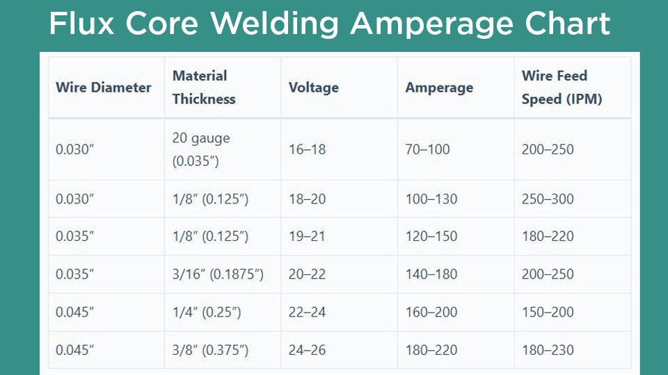
The first table uses published settings for a specific 0.030- and 0.035-inch E71T-GS self-shielded wire. It is useful because it ties amperage to both thickness and joint type. Do not transfer these numbers blindly to a different wire. The second table shows broader operating windows for representative E71T-11 and E71T-1 products.
IPM means inches per minute of wire feed speed. CTWD means contact-tip-to-work distance. DCEN means electrode negative; DCEP means electrode positive.
| Wire / Classification | Steel Thickness and Joint | Amperage | Voltage | Wire Feed Speed | CTWD |
|---|---|---|---|---|---|
| 0.030 in E71T-GS | 18 gauge, fillet/lap/T-joint | 40–60 A | 12–14 V | 64–100 IPM | 1/2 in |
| 0.030 in E71T-GS | 16 gauge, fillet/lap/T-joint | 80–110 A | 13–17 V | 128–200 IPM | 1/2 in |
| 0.030 in E71T-GS | 10 gauge, fillet/lap/T-joint | 125–160 A | 15–21 V | 200–350 IPM | 1/2 in |
| 0.030 in E71T-GS | 10 gauge, square groove | About 145 A | 21–23 V | 400 IPM | 5/8 in |
| 0.035 in E71T-GS | 16 gauge, fillet/lap/T-joint | 50–90 A | 14–16 V | 60–100 IPM | 1/2 in |
| 0.035 in E71T-GS | 10 gauge, fillet/lap/T-joint | 100–125 A | 17–22 V | 125–200 IPM | 1/2 in |
| 0.035 in E71T-GS | 10 gauge, square groove | 100–125 A | 19–22 V | 125–200 IPM | 1/2 in |
| 0.035 in E71T-GS | 1/4 in, fillet/lap/T-joint | 220–245 A | 22–26 V | 400–500 IPM | 1/2 in |
Those E71T-GS values come from the Harris Ten Gauge E71T-GS technical sheet. That product is intended for single-pass work. The 1/4-inch row also demands far more output than a typical 120-volt hobby welder can supply, so machine capacity and duty cycle must be checked.
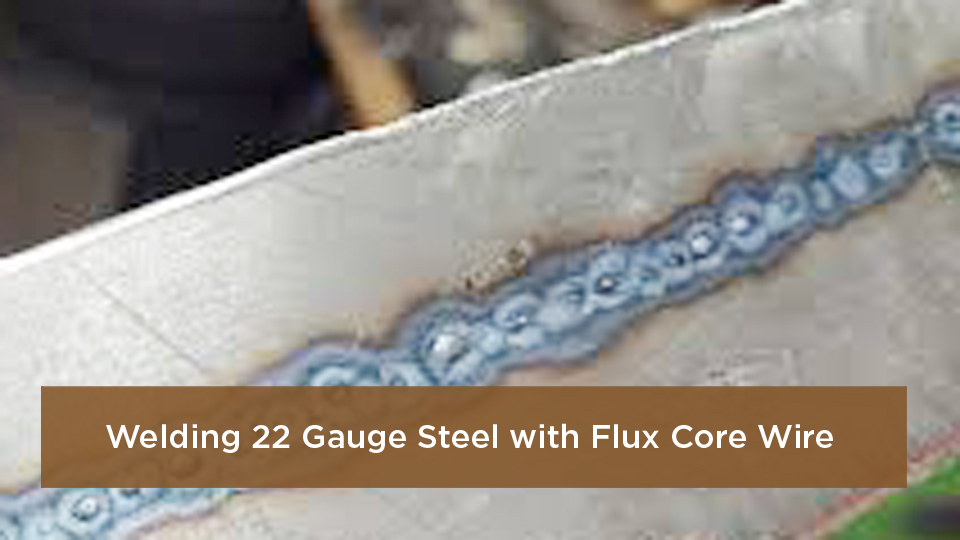
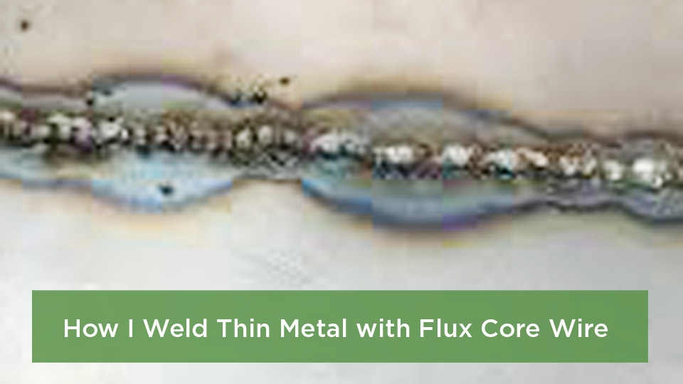
Note: Twenty-gauge sheet is thinner than the lowest thickness in that E71T-GS table. Use the lowest setting recommended by your exact wire and welder, make short staggered welds, allow cooling time, and test on matching scrap. A generic 70–100 amp recommendation for 20-gauge steel is likely too hot for many small-wire setups.
| Example Wire | Diameter | Polarity / Gas | Published Operating Window | CTWD |
|---|---|---|---|---|
| E71T-11 self-shielded | 0.030 in | DCEN / no gas | 25–125 A, 14–16 V, 55–225 IPM | 1/2 in |
| E71T-11 self-shielded | 0.035 in | DCEN / no gas | 55–120 A, 17–20 V, 75–160 IPM | 1/2 in |
| E71T-11 self-shielded | 0.045 in | DCEN / no gas | 115–200 A, 15–18 V, 105–195 IPM | 1/2 in |
| E71T-1 gas-shielded | 0.045 in | DCEP / 100% CO2 in the cited sheet | 130–275 A, 22–31 V, 175–525 IPM | 3/4 in |
The E71T-11 rows are the published range for Hobart Fabshield 21B. The gas-shielded row comes from the Harris Dynashield E71T-1 technical sheet. The Dynashield sheet says to use lower voltages with an argon/CO2 blend than with 100% CO2.
These operating windows do not assign one setting to one thickness. Joint design, pass size, position, base-metal grade, preheat, and required properties still matter. Use the exact manufacturer table for the spool in your machine.
How to Use the Amperage Chart
- Identify the base metal. Confirm that it is weldable carbon or mild steel. Do not assume a stainless, cast, hardened, coated, or unknown steel can use this chart.
- Measure the actual thickness. Gauge labels can be confusing, and coatings do not count as base-metal thickness.
- Read the full wire label. Record the AWS classification, diameter, manufacturer, polarity, shielding gas, allowed positions, and single- or multipass limits.
- Check the welder chart and duty cycle. The machine must be able to feed the wire and deliver the required voltage and current without exceeding its rated duty cycle.
- Set polarity before feeding wire. Many small self-shielded wires run DCEN, while common gas-shielded E71T-1 wires run DCEP. The spool label and datasheet take priority.
- Set the listed CTWD. Measure from the contact tip to the work, not from the nozzle. A nozzle can hide the tip.
- Set voltage and wire feed speed. On a CV machine, use WFS to move current into range and voltage to stabilize arc length and bead shape.
- Run a test coupon. Use the same material, thickness, joint, position, fit-up, and surface preparation as the project.
- Change one variable at a time. Make small adjustments, record them, remove slag, and compare each bead.
Pro Tip: Write the wire classification, voltage, WFS, CTWD, joint, position, and travel speed on the test coupon. That makes a successful setup repeatable and helps you spot what changed when the next weld behaves differently.
Choosing the Right Flux Core Wire
The letters and numbers on the spool matter more than the phrase “flux core.” Common carbon-steel choices include:
- E71T-GS: A general classification often used for small-diameter, self-shielded wire and single-pass sheet or light repair work. Position and thickness limits are product-specific.
- E71T-11: A self-shielded carbon-steel classification available in several diameters. Many products allow all-position and multipass welding, but the maximum plate thickness, pass count, and mechanical properties vary by product.
- E71T-1: A gas-shielded carbon-steel classification commonly used in fabrication. It normally requires DCEP and the exact shielding gas named on the datasheet.
Wire diameter affects the usable current range and how easily you can control thin material:
- 0.030 inch: Usually the easiest small-diameter choice for thin sheet and lower-output machines.
- 0.035 inch: A broad general-purpose size for light fabrication and repair when the machine supports it.
- 0.045 inch: Better suited to higher-output machines, thicker joints, or higher deposition rates. It is not automatically the correct choice for every 1/4-inch weld.
The chart in this article does not apply to stainless steel. Stainless FCAW requires a stainless classification matched to the base metal, corrosion requirements, shielding method, and procedure. The same warning applies to weathering steel, quenched-and-tempered steel, cast iron, and unknown scrap.
Products Worth Considering
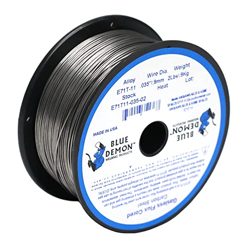
GASLESS: E71T-11 does not require a shielding gas. The flux core inside the wire acts in place of the shielding gas. This makes the wire very versatile and perfect for mobile jobs, outdoor jobs, and people who do not have access to shielding gas.

GASLESS: E71T-11 does not require a shielding gas. The flux core inside the wire acts in place of the shielding gas. This makes the wire very versatile and perfect for mobile jobs, outdoor jobs, and people who do not have access to shielding gas.

E71T-11 FLUX CORE WIRE: Known for its smooth arc action and minimal spatter, it operates efficiently without the need for external shielding gas, making it ideal for outdoor use or drafty environments where gas-shielded processes might struggle. This electrode offers excellent slag removal and good weld penetration.
What Changes the Amperage You Actually Get
- Wire feed speed: On a conventional CV setup, more WFS generally produces more current because more electrode must be melted each second.
- Electrical stickout: A longer stickout increases resistance heating in the wire and normally lowers arc current at the same WFS. A shorter stickout normally raises current. Stay inside the manufacturer’s CTWD range instead of using extreme stickout as a heat control.
- Voltage: Voltage mainly changes arc length, bead width, and arc behavior. Too little voltage can make the wire stub into the puddle; too much can create a long, harsh arc, spatter, undercut, or burnback.
- Travel speed: Slow travel puts more heat and filler into each inch. Fast travel can reduce bead size and cause incomplete fusion.
- Joint design and fit-up: A tight lap joint, open-root groove, fillet weld, and butt joint do not need the same settings even at the same thickness.
- Welding position: Vertical and overhead work usually needs a smaller, faster-freezing puddle and a procedure approved for that position.
- Input power and duty cycle: Long extension cords, low supply voltage, tripped thermal protection, and an undersized machine can prevent the welder from delivering the expected output.
Setting Up Your Welder for Flux Core
- Clean the work and clamp area. Remove paint, grease, moisture, heavy rust, and loose scale. Attach the work clamp to clean metal close to the weld.
- Inspect the cable and gun. Look for damaged insulation, loose connections, a worn liner, a clogged tip, or a kinked gun cable.
- Install the correct drive roll. Use the groove type and size specified by the welder or wire maker. Knurled rolls are common for tubular wire because they can feed with less pressure.
- Set only enough drive-roll pressure. Excess pressure can deform tubular wire and accelerate liner wear. Too little pressure causes slipping.
- Match the contact tip to the wire. A worn or oversized tip can make the arc erratic; an undersized or damaged tip can cause feeding trouble.
- Verify polarity at the internal terminals. Changing the front-panel process selection does not correct reversed gun and work leads on every machine.
- For FCAW-G, check the gas system. Use the specified gas, flow range, clean nozzle, leak-free connections, and protection from wind.
- Confirm the machine’s output and duty cycle. A chart calling for 200 amps does not mean a 90-amp or 120-amp machine can make the weld by turning the controls to maximum.
Warning: Never weld on metal that still has unknown paint, plating, solvent, fuel, oil, or chemical residue. Keep chlorinated solvent vapors away from welding arcs. Galvanized, stainless, and coated metals can require specific fume controls, respiratory protection, and work practices. Do not weld on a closed container.
Products Worth Considering

E71T-GS FLUX CORE WIRE: This self-shielding, AWS E71T-GS flux-cored wire excels due to its advanced core design, delivering exceptional arc stabilization and high feedability for effortless welding. The core also incorporates powerful deoxidizing agents, ensuring clean, reliable welds even when welding through light rust or mill scale.

E71T-GS FLUX CORE WIRE: This self-shielding, AWS E71T-GS flux-cored wire excels due to its advanced core design, delivering exceptional arc stabilization and high feedability for effortless welding. The core also incorporates powerful deoxidizing agents, ensuring clean, reliable welds even when welding through light rust or mill scale.

Welding Easy and Quick: AWS E71T-GS 030” Flux Core welding wire (The actual Net Weight of Wire is 2LB), no need for shielding gas, install it then you can welding all positions, single and multi pass welding. Great for T-joints, butt welds & lap welds.
Gun Angle, Stickout, and Travel Technique
Flux-cored wire normally uses a drag technique: point the gun back toward the puddle and pull it away from the completed weld. Miller’s flux-cored welding guide recommends a typical travel angle of about 5–15 degrees and warns that excessive angle can increase spatter and reduce penetration.
- Keep CTWD steady. Small-diameter self-shielded products may specify about 1/2 inch, while a gas-shielded 0.045-inch wire may specify 3/4 inch. Follow the spool data.
- Use the correct work angle. Aim roughly 45 degrees into a T-joint and about 90 degrees to a butt joint, then add the required travel angle.
- Favor stringer beads. Wide weaving can trap slag or reduce fusion unless the procedure specifically permits it.
- Watch the leading edge of the puddle. Keep the arc on the joint and sidewalls rather than riding on top of slag.
- Clean every pass. Remove slag and inspect for defects before placing the next bead.
Vertical and Overhead Flux Core Settings
Do not apply a blanket “reduce amperage by 10–15%” rule to every flux-cored wire. Some wires are approved for vertical-up, some for vertical-down, some for both, and others only for flat and horizontal welding. Start with the position-specific range in the datasheet or approved procedure.
For an all-position wire, out-of-position settings are often near the lower or middle part of its approved range. Use a controlled puddle, a consistent CTWD, a small drag angle, and stringer beads. If the puddle sags, do not simply lengthen stickout beyond the approved range; correct the WFS, voltage, travel, bead size, or technique.
Joint Preparation and Multipass Welds
Thicker steel does not become a sound joint just because amperage increases. Joint preparation gives the arc access to the root and sidewalls. For butt joints above about 1/4 inch, beveling is often needed, but the correct bevel angle, root face, root opening, backing, and pass sequence depend on the procedure.
Before a multipass weld:
- Confirm that the exact wire permits multipass welding and the intended plate thickness.
- Use the required preheat and interpass temperature for the base metal and procedure.
- Remove slag, spatter, and visible defects between passes.
- Keep each bead within the allowed size and heat-input range.
- Do not substitute a hobby chart for a WPS on structural, pressure, lifting, transportation, or machinery work.
Common Flux Core Problems and Fixes
| Problem | Likely Causes | What to Change |
|---|---|---|
| Wire stubs into the work | WFS too high for voltage, voltage too low, CTWD too short, poor work connection | Raise voltage slightly or reduce WFS within the datasheet range; restore the specified CTWD and clean the clamp point |
| Burnback to the tip | WFS too low, voltage too high, CTWD too long, restricted wire feeding | Raise WFS or lower voltage slightly; inspect the tip, liner, roll tension, and gun cable |
| Burn-through | Excess current or voltage, slow travel, large root gap, wire too large, poor fit-up | Use a lower approved setting, smaller wire, faster travel, short staggered welds, tighter fit-up, or a suitable backing bar |
| Lack of fusion | Low current, fast travel, poor gun angle, unprepared thick joint, arc placed on the puddle instead of the joint | Increase WFS within range, correct voltage and angle, slow slightly, clean the joint, and bevel when the procedure requires it |
| Porosity | Dirty or wet metal, damp or rusty wire, excessive CTWD, wind or gas leak on FCAW-G, contaminated nozzle | Clean and dry the work, replace damaged wire, set CTWD, repair the gas system, and shield FCAW-G from drafts |
| Excessive spatter | Voltage/WFS mismatch, wrong polarity, long arc, excessive travel angle, contamination | Verify polarity, return to the published range, shorten the arc without violating CTWD, reduce angle, and clean the work |
| Slag inclusion | Poor bead placement, wide weave, low heat at sidewalls, welding over slag | Use stringers, direct the arc at the joint edges, maintain fusion, and clean every pass completely |
| Undercut | Excess voltage or current, fast travel, wrong angle, bead too large | Reduce the setting within range, slow enough to fill the toes, correct the angle, or use smaller passes |
| Worm tracks | Gas escaping through solidifying slag, high voltage, surface contamination, unsuitable technique | Lower voltage within the wire’s range, clean the plate, maintain the specified stickout, and follow the manufacturer’s technique guidance |
Visual inspection can find obvious cracks, porosity, undercut, overlap, poor profile, and missed areas. It cannot prove that a weld has full penetration, adequate internal fusion, required toughness, or code compliance. A hammer test on a casual practice coupon can teach you something about technique, but it is not a substitute for a qualified bend test, macroetch, nondestructive examination, or code inspection.
Pros and Cons of Flux Core Welding
Advantages
- Outdoor capability: Self-shielded wire does not depend on an external gas cloud, so it is less vulnerable to wind than FCAW-G or MIG.
- High deposition: Suitable wires and machines can deposit metal quickly on fabrication and repair work.
- Position options: Many classifications are available for flat, horizontal, vertical, and overhead welding.
- Surface tolerance: Some wires handle light scale or coatings better than solid wire, though cleaning is still required.
- Portability: FCAW-S eliminates the gas bottle and regulator.
Limitations
- Slag: It must be removed between passes and before inspection or finishing.
- Spatter and smoke: Self-shielded wire can produce more visible fume and cleanup than a well-tuned gas-shielded process.
- Wire-specific rules: Polarity, pass limits, positions, CTWD, and thickness limits vary more than many beginners expect.
- Thin-sheet control: Some small FCAW machines have coarse voltage taps, making very thin sheet harder to weld without burn-through.
- Fume exposure: Flux ingredients, base metal, and coatings can produce hazardous airborne contaminants.
Applications for Flux Core Welding
- General DIY and shop work: Gates, brackets, carts, noncritical repairs, and practice coupons are common uses when the material and wire are compatible.
- Farm and equipment repair: FCAW-S is convenient outdoors, but load-bearing or safety-related repairs should follow the equipment maker’s procedure and applicable requirements.
- Automotive work: Flux core may be used for some exhaust or noncritical steel repairs. Vehicle frames, suspension points, hitches, roll cages, and crash structures are not beginner chart projects.
- Construction and structural fabrication: FCAW is widely used, but production work relies on approved WPSs, qualified welders, suitable consumables, and inspection—not a general settings chart.
- Shipbuilding and heavy fabrication: Industrial FCAW-S and FCAW-G wires support high deposition and out-of-position work under controlled procedures.
Safety Considerations
Arc welding can cause electric shock, burns, eye injury, fire, explosions, and harmful fume exposure. Follow the welder manual, wire safety data sheet, site rules, and applicable regulations.
- Eye and face protection: Wear safety glasses with side protection under a welding helmet. OSHA’s filter-lens table lists a minimum shade 7 below 60 amps and minimum shade 10 from 60 through 500 amps for GMAW and FCAW. Start darker and move lighter only without going below the minimum.
- Skin protection: Wear flame-resistant clothing, dry welding gloves, closed footwear, and protection for the neck and ears.
- Ventilation: Keep your head out of the plume and use effective local exhaust or mechanical ventilation. A fan that blows across FCAW-G can ruin shielding, so capture fumes without sweeping gas away from the arc.
- Respiratory protection: A respirator must be selected for the actual hazard, fit-tested where required, and used as part of a proper respiratory-protection program. It does not replace ventilation.
- Fire prevention: Remove combustibles, protect items that cannot be moved, keep an appropriate extinguisher nearby, and inspect hidden areas where sparks can travel.
- Electrical safety: Keep gloves and clothing dry, inspect leads, avoid damaged insulation, and disconnect input power before servicing the wire path or changing internal connections.
- Confined spaces: Do not treat a tank, vessel, compartment, or similar space as a normal welding area. Ventilation, atmospheric testing, rescue planning, outside attendance, and other controls may be required.
OSHA’s welding, cutting, and brazing requirements cover fire prevention, PPE, ventilation, confined spaces, coatings, and hazardous materials. Workplace rules can be stricter.
Conclusion
A flux core welding amperage chart is most useful when it is tied to a specific wire, joint, and machine. On a CV welder, start with the manufacturer’s voltage and WFS, verify polarity and CTWD, and let the resulting current fall within the wire’s approved range. Then tune the weld on a matching coupon.
Do not chase amperage alone. Stable feeding, clean metal, correct joint preparation, consistent gun angle, steady travel, slag removal, and safe fume control all matter. For critical work, stop at the limits of a general chart and use the approved procedure, qualifications, and inspection the job requires.
Frequently Asked Questions
What is the best flux core wire for beginners?
A 0.030-inch self-shielded carbon-steel wire that is approved for your welder and project is often easy to control. Do not choose by diameter alone. Read the full classification, polarity, position, pass, and thickness limits. E71T-GS may be single-pass, while an E71T-11 product may allow multipass welding.
Can I use flux core welding on 20-gauge steel?
Yes, if the welder and exact wire can run low enough, but 20-gauge steel burns through easily. Use small-diameter wire, the lowest approved setting, tight fit-up, short staggered welds, and cooling time. Test on matching scrap first. Do not assume a generic 70–100 amp setting is suitable.
Why am I getting so much spatter with flux core welding?
Common causes are the wrong polarity, a voltage and WFS mismatch, excessive travel angle, inconsistent CTWD, contamination, or poor wire feeding. Return to the exact wire’s published range, verify internal polarity connections, clean the work, and change one setting at a time.
Do I need a special welder for flux core wire?
You need a wire-feed welder rated for the wire diameter and process. It must provide the required output, correct polarity connections, suitable drive rolls, a matching contact tip, and enough duty cycle. Gas-shielded FCAW also needs a gas solenoid, regulator, hose, and the specified shielding gas.
Is flux core normally DCEN or DCEP?
Many small self-shielded wires, including common E71T-GS and E71T-11 products, use DCEN. Common gas-shielded E71T-1 products use DCEP. Those are patterns, not a universal rule. The spool label and manufacturer datasheet always control.
Can a 120-volt flux core welder weld 1/4-inch steel?
Some 120-volt machines advertise 1/4-inch capacity under specific conditions, often with joint preparation and multiple passes. Check the machine’s rated output, duty cycle, wire chart, and pass limits. A maximum-thickness claim does not mean every 1/4-inch joint can be welded safely in one pass.
How do I know whether a flux core weld is strong enough?
A uniform bead with no visible cracks, porosity, overlap, undercut, or slag helps, but appearance alone cannot prove strength. Noncritical practice coupons can be cut, bent, or macroetched to check fusion. Structural and safety-critical welds require the specified procedure, acceptance criteria, and inspection method.
Sources
- Harris Ten Gauge E71T-GS Technical Sheet — thickness-specific settings, DCEN polarity, joint types, and single-pass use.
- Hobart Fabshield 21B Data Sheet — E71T-11 polarity, operating windows, CTWD, positions, and product limits.
- Harris Dynashield E71T-1 Technical Sheet — gas-shielded 0.045-inch operating parameters, polarity, CTWD, and gas notes.
- Miller Flux-Cored Welding Basics — setup, cleaning, wire selection, drag technique, travel angle, and test-weld guidance.
- OSHA 29 CFR 1910.252 — welding fire prevention, PPE, ventilation, coatings, confined spaces, and hazardous-material controls.
- OSHA 29 CFR 1910.133 — minimum protective lens shades for FCAW and other welding processes.