When I first set up a garage shop, one problem showed up on almost every project: keeping parts square and steady without covering the bench with bulky fixtures. A small shift during a tack weld can change a frame’s diagonal measurement, open a root gap, or make repeated parts come out different.
DIY welding jigs helped me control that fit-up while keeping the shop flexible. The best designs are simple: they establish one or two reliable reference surfaces, leave room for clamps and the torch, and release the part without forcing it.
This guide covers four useful small-shop jigs, how to build and check them, and the safety limits that matter when sparks, fumes, hot metal, and combustible materials share a tight workspace.
Quick Answer
A DIY welding jig is a reusable holder that locates, supports, and clamps parts for more accurate, repeatable fit-up. In a small shop, useful options include a 90-degree corner jig, a removable stop block, a compact hole-grid fixture table, and steel V-blocks for pipe or tube.
Key Takeaways
- Design from clear reference points, then add only enough clamping force to seat the parts.
- Use steel near the arc; keep wood, MDF, rubber, coatings, and other combustibles out of the hot-work area.
- Tack in a balanced sequence and recheck diagonals before completing the welds.
- Treat voltage, wire speed, amperage, filler, gas, and joint preparation as procedure-specific—not universal jig settings.
- Test the jig with scrap before using it for a batch or any safety-critical part.
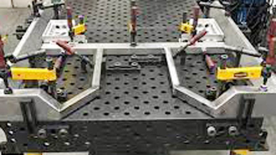
Image by made-in-china
At a Glance
| Time Required | About 30 minutes for a simple stop; several hours for a welded corner jig; a half day or more for a compact fixture table |
| Difficulty | Beginner to intermediate, depending on layout accuracy and drilling |
| Tools Needed | Square, tape or rule, scribe, clamps, metal-cutting saw, drill or drill press, deburring tools, and a suitable welder |
| Cost | Low when usable scrap and clamps are already available; higher for flat plate, casters, precision holes, and new hardware |
What Is a Welding Jig and Why Does It Improve Fit-Up?
A welding jig is a task-specific device that locates and holds parts in a planned position. Stops establish length, faces establish angle, pins establish location, and clamps keep the work seated against those references. The terms jig and fixture are often used loosely in small shops, but both aim to make fit-up more repeatable.
The American Welding Society’s guidance on weldment tooling lists tighter fit-up, fewer measurements, less distortion, better consistency, and higher productivity among the benefits of fixturing. Those benefits come from controlling part location—not from making the weld automatically strong.
Weld quality still depends on the base metal, joint design, preparation, filler metal, shielding, procedure, heat input, and operator technique. A jig can also create problems if it blocks access, traps the finished part, conducts current through bearings or hinges, or restrains shrinkage so severely that stress rises.
I first appreciated simple jigs while repeating square-tube assemblies in a crowded shop. A basic angle stop removed repeated measuring and made the parts easier to compare. That is where small jigs earn their space: repeated brackets, frames, gates, racks, furniture, repair parts, and other work that uses the same dimensions more than once.
A jig controls location and fit-up. It does not replace a sound welding procedure, inspection, or engineering requirements for a safety-critical part.
Plan the Jig Before You Cut Metal
A useful jig starts with the finished part, not the scrap pile. Sketch the assembly and mark the surfaces or centerlines that matter most. These become your datums—the references every workpiece touches before it is clamped.
- Choose the key dimensions: angle, length, centerline, hole location, height, or diagonal.
- Plan weld access: leave room for the gun, torch, electrode, filler rod, nozzle, cup, and your gloved hand.
- Plan the tack sequence: provide access to opposite sides so the first tacks do not pull the assembly one way.
- Plan release: use removable stops, slotted clamps, tapered pins, or an open side so the cooled part can come out.
- Plan for heat: keep sensitive clamp screws, casters, plastic handles, magnets, and painted surfaces away from the arc and hot zone.
- Plan verification: include a surface or hole that makes it easy to check the jig with a square, rule, gauge pin, or test coupon.
Pro Tip: Make one stop adjustable until the test parts prove the dimension. After the trial run, lock the setting with a jam nut, dowel, witness mark, or bolted keeper instead of relying on clamp pressure alone.
The Real Challenges of Welding Accurately in Tight Quarters
Small shops magnify ordinary layout problems. Limited torch travel, poor sight lines, cords across walkways, weak lighting, and crowded benches make it harder to check square or reach an opposite tack. Hot work also needs separation from fuel, finishes, rags, cardboard, wood dust, and stored chemicals.
Heat distortion is another challenge. Weld metal and the nearby base metal expand when heated and contract as they cool. If the tack sequence, weld size, or restraint is unbalanced, a square assembly can twist even when the jig started flat.
Material behavior also changes the plan. Thin mild steel can burn through when gaps are large. Stainless steel needs contamination control and fume precautions. Aluminum conducts heat quickly, has a persistent oxide layer, and needs clean, alloy-compatible tools and filler selection.
Start with clean, sound material and a joint design suited to the thickness and service. Do not apply one bevel angle or root gap to every joint. For structural, pressure-retaining, lifting, roll-cage, trailer-hitch, or road-use parts, follow the applicable drawing, code, manufacturer’s repair procedure, or qualified welding procedure specification.
Positioning a part can free bench space, but do not hang welding work from garage rafters, plumbing, shelving, or an improvised chain. Use a rated welding positioner, stand, clamp, or engineered lifting point with enough capacity for the work and the forces created while fitting it.
Essential Tools and Materials for Building DIY Welding Jigs
You do not need a full machine shop for basic jigs. A reliable square, a steel rule or tape, a sharp scribe, clamps, a metal-cutting saw, and a drill are enough for many projects. A drill press improves hole alignment, while a deburring tool, file, and flap disc make parts safer to handle and easier to seat.
| Material | Best Use | Advantages | Limits and Precautions |
|---|---|---|---|
| Steel angle and flat bar | Stops, corner arms, gussets, clamp pads | Rigid, weldable, and heat-resistant | Can distort during fabrication; remove mill scale, rust, paint, and zinc from the weld area |
| Steel plate and tubing | Bases, compact tables, support frames | Durable and easy to ground through a clean work-clamp connection | Heavy; thin plate needs close support to stay flat |
| Aluminum bar or extrusion | Light-duty templates and dedicated aluminum fit-up | Light and nonmagnetic | Soft, easy to dent, and vulnerable to arc damage; keep it out of the direct weld zone |
| Wood, plywood, or MDF | Cold layout templates away from hot work | Easy to cut and revise | Combustible; do not use as an exposed welding base, spark stop, or arc-side clamp surface |
| Copper or brass sheet | Removable backing, non-marring shims, spatter-resistant contact faces | Conducts heat and weld metal is less likely to fuse to it | Keep unknown, plated, painted, or cadmium-bearing alloys out of the heat zone |
| Bolts, pins, and clamps | Adjustable stops and replaceable holding points | Serviceable and easy to change | Protect threads from spatter and do not exceed the hardware or clamp rating |
For carbon-steel jigs, common fillers may include ER70S-series wire for GMAW or E70-series electrodes for SMAW, but the exact classification and storage requirements depend on the procedure. Aluminum filler such as 4043 or 5356 must be selected for the base alloy, service temperature, strength, corrosion, and finishing requirements rather than chosen by habit.
Warning: Do not seal a wooden jig with polyurethane and then expose it to sparks. OSHA’s hot-work rule calls for moving combustibles at least 35 feet where practical or shielding them with suitable fire-resistant protection. Also, never collect hot sparks or glowing metal with an ordinary shop vacuum; let debris cool and use equipment approved for the material and hazard.
Products Worth Considering

INCLUDES: (4) Horizontal quick release toggle clamp (Type-225D)

【High Quality Materials】The main body of the cast iron welders angle clamp is made of high-quality cast iron and steel materials, with high tensile strength and more durable characteristics. The surface of the welding table clamp is sprayed with plastic to prevent rust and corrosion.

Fixed Clamps: Mini toggle clamp with rubber tip, cam lever hold down clamp for CNC fixtures/workholding clamps. Quick release clamps with non-slip, oil and stain resistant red vinyl solid handles for woodworking clamps.
How to Control Distortion Without Over-Clamping
A rigid jig can help a weldment stay aligned, but more clamp force is not always better. Excessive restraint can dent tubing, close a required root opening, make the part difficult to release, or concentrate shrinkage stress.
- Seat, do not crush: tighten each clamp only until the work is fully against the datum.
- Tack symmetrically: place small tacks on opposing sides and recheck the assembly after each pair.
- Use the smallest weld that meets the design: unnecessary weld metal adds heat and shrinkage.
- Balance the sequence: alternate sides, use short segments where the procedure permits, and avoid completing one long side before the opposite side.
- Let the assembly cool safely: do not force a hot part out of the jig or quench it unless the approved procedure requires that treatment.
- Measure before release: check diagonals, angle, and critical offsets while correction is still possible.
If a jig repeatedly produces the same error, do not compensate by hammering every finished part. Check the datum surfaces, stop locations, tack sequence, clamp force, and heat pattern, then correct the jig or process.
Simple DIY Corner Clamp Jig for Square Tubing Welds
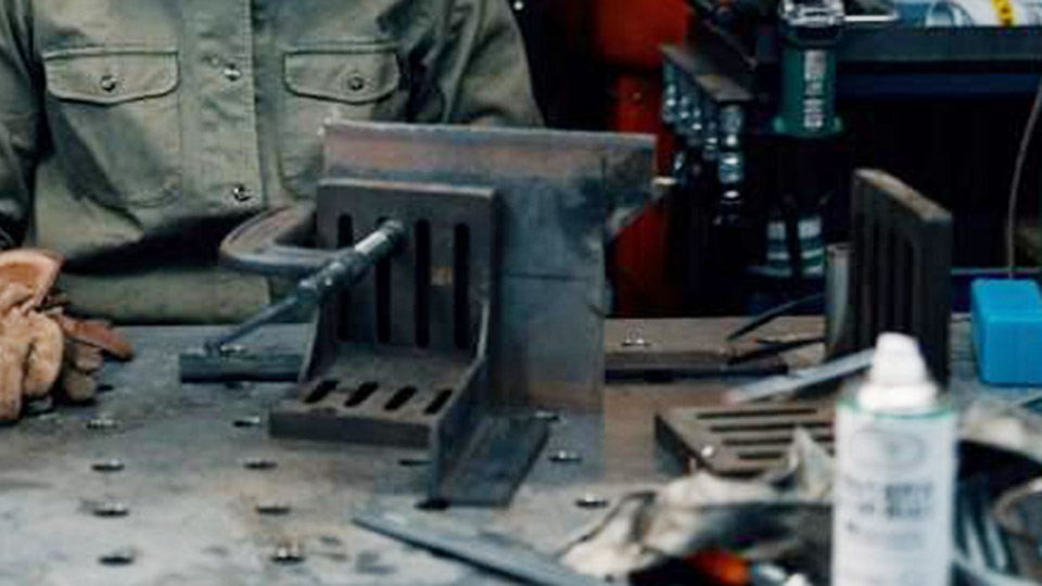
A compact corner jig is one of the most useful small-shop fixtures. It supports two pieces at 90 degrees while leaving the joint accessible for tack welds. It works well for frames, brackets, shelves, furniture legs, and repeated square-tube assemblies.
I built an early version from steel angle and a flat-bar gusset. The main lesson was to weld the jig in a balanced sequence and keep the locating faces clear of weld beads and spatter.
Basic materials: two straight pieces of steel angle or flat bar, one steel base or gusset, clamps, and optional removable copper or brass shims.
- Cut the two locating arms long enough to support the stock without blocking the joint. Deburr every edge.
- Place the arms on a flat steel surface and set them to 90 degrees with a verified square.
- Clamp the arms securely, then measure from several points to confirm that both locating faces are straight and square.
- Add small tacks on the back or outside of the jig. Allow them to cool enough to handle, then recheck the angle.
- Add the gusset or base with short, balanced welds. Alternate sides instead of running one long bead.
- Dress only the spatter or weld metal that interferes with the locating faces. Do not grind away the reference edges.
- Test with two pieces of scrap tubing. Tack the sample, release it after cooling, and compare the diagonals or corner angle.
- Add replaceable noncombustible shims if the jig must protect a finished surface or accommodate a second stock size.
Set the welder from the machine’s chart or manual for the actual metal, thickness, joint, wire or electrode, gas, and position. A fixed statement such as “16 volts for thin stock” is not reliable across machines and transfer modes.
For aluminum, use clean, dedicated tools and select filler from an alloy compatibility chart. Conventional TIG welding of aluminum normally uses AC with argon; amperage is controlled for the actual thickness and joint rather than set to a universal 100–120 amps.
Pro Tip: Tack the workpiece where it can still move slightly, check square, then add the opposing tacks. The jig should make correction easier, not hide movement until the weld is complete.
Scrap Stop Block Jig for Repeat Cuts and Alignments
A stop block establishes a repeated length or location. It can be attached to a bench, saw fence, fixture rail, or dedicated base, but it must not trap the work or offcut against a moving blade.
In my own fence and bracket work, a simple stop saved repeated measuring. The safest version near a saw is usually a metal flip stop or an offset stop that the work clears before it reaches the blade.
- Cut and deburr one sample part to the required finished length.
- Place the sample in the correct cutting or fit-up position and mark the stop location.
- Install a rigid metal stop with bolts, a clamp, or a slotted bracket. Keep it far enough from the blade that the offcut cannot bind between the stop and blade.
- Make a test cut and measure it with the same tool and reference method used for the drawing.
- Add a second stop or spacer only when it improves height or side alignment without trapping the part.
- Mark the stop setting and periodically check that vibration has not moved it.
Do not glue a stop in place as a substitute for sound mechanical fastening. Adhesive can soften from heat, hide movement, or make adjustment difficult. On a band saw, use the blade maker’s speed and feed chart for the exact alloy, hardness, section, blade, coolant, and machine. The Starrett band-saw reference guide, for example, shows that speed varies widely by steel grade; “300 SFPM for steel and slower for aluminum” is not a universal rule.
| Jig Type | Typical Footprint | Best Control | Main Limitation |
|---|---|---|---|
| Corner clamp | About 12 × 12 inches | 90-degree fit-up | Usually fixed to one angle and stock range |
| Stop block | About 6 × 24 inches | Repeated length or location | Must be set up to prevent blade binding |
| Mini fixture table | About 24 × 36 inches | Multiple datums and clamp positions | Heavier, slower, and more costly to build |
| Pipe V-block jig | Varies with tube length | Centerline and rotation | Needs diameter-appropriate supports and access |
Building a Modular Mini Fixture Table for Small-Space Welding
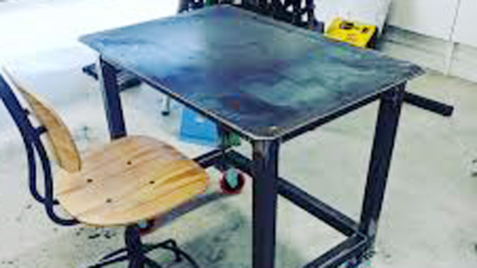
A compact fixture table provides a flat reference surface and movable clamp points without taking over the shop. A 24 × 36-inch top can roll under a bench, but its plate thickness, support frame, holes, legs, and casters must be designed as one system.
A quarter-inch plate may work for light fabrication when it is closely supported by a stiff frame. Thicker plate resists local bending better but adds substantial weight. Decide what the table must hold before buying material, and rate the frame and casters for the full table, fixture, and workpiece load.
- Choose a top size and supported load that fit the available storage space and projects.
- Build a square support frame from straight steel tubing, with crossmembers close enough to support the plate.
- Place the plate on the frame and check flatness before welding. Use short, balanced attachments or bolted construction to limit distortion.
- Lay out the hole grid from two verified edges. Center-punch and drill test holes before committing to the full pattern.
- Use a drill press where possible. Use a magnetic drill only when the tool manufacturer permits the plate thickness, attachment method, cutter, and setup.
- Size the holes for the actual commercial or homemade pins and clamps. A nominal half-inch pin will not reliably fit a rough nominal half-inch drilled hole after burrs, coating, or spatter.
- Add rated casters, with brakes or leveling feet that prevent movement while welding.
- Deburr the holes, protect threads and mechanisms from spatter, and verify the top with a straightedge and square.
- Build removable stops, posts, and V-blocks that cannot fall through, turn unexpectedly, or fuse to the workpiece.
A hole grid is practical for most DIY tables. True T-slots require suitable machined or fabricated track and should not be cut casually into a thin plate. Likewise, filler selection for stainless parts depends on the exact base alloys and procedure; 308L is common for some 304-type applications, but it does not “match” every stainless steel.
My first mobile table needed shims because the floor and leg assembly were not level. Leveling feet are a cleaner long-term fix because they unload the casters and make the reference surface more stable.
Products Worth Considering

【Universal Welding Table for Heavy-Duty Projects】This robust metal welding table features a spacious 36" x 24" welding table top, offering ample workspace for a variety of tasks. The integrated underneath storage panel significantly enhances organization, making it one of the most functional welding tables for shop use. With an impressive 1200 lb load capacity, it handles heavy materials with ease.

Zero-Deflection Under Heat & Load – The 3.5mm reinforced frame and heat-treated 2.8mm deck absorb welding contraction stress, keeping your work perfectly coplanar after cooling. No warped joints, no rework.

12-Piece Welding Table Fixture Pin Set: This set includes 12 fixture pins (5/8" x 1" x 2") for welding tables with 5/8" (16mm) Holes. Easy to use, these pins ensure secure positioning for precise welds, improving efficiency across various welding tasks.
Pipe and Tube Alignment Jig for Round Stock
Round stock rolls, and two cut ends can look aligned while their centerlines are offset. A pair of steel V-blocks, saddles, or commercial pipe supports can hold the tube at a repeatable height while a chain clamp, strap clamp, or top clamp controls rotation.
For exhaust, frame, or tube work, keep the supports far enough from the joint for torch access and close enough to prevent sag. Wood V-blocks may be useful for cold layout, but exposed wood does not belong beside the welding arc.
- Cut or fabricate two matching steel V-blocks and mount them to a straight base or fixture-table holes.
- Set the blocks far enough apart to support the work without blocking the joint.
- Place the tube in the V-blocks and use a straightedge, square, level, laser, or centerline marks appropriate to the assembly.
- Apply only enough top-clamp or chain-clamp force to seat the tube. Protect thin or finished tubing from clamp damage with clean, noncombustible shims.
- Check the root opening, high-low mismatch, clocking marks, and overall centerline.
- Tack at opposing points—often near 12 and 6 o’clock, then 3 and 9 o’clock—when the procedure and access allow.
- Recheck alignment before adding the full weld sequence.
ER70S-2 is a common carbon-steel GTAW filler in some applications, while ER70S-6 is common GMAW wire. Voltage is a machine output variable for GMAW, not a hand-set “filler setting” for manual GTAW. Select the process, filler, and parameters from the material specification, procedure, and machine guidance.
Exhaust components, roll cages, pressure piping, steering parts, and other safety-related assemblies may have material, code, bend, joint, and inspection requirements that a home-built alignment jig cannot address by itself.
Step-by-Step Guide to a Hybrid Corner-and-Stop Jig
A hybrid jig combines a square corner with an adjustable stop, making it useful for repeated brackets or tabs.
- Sketch the part and references: mark a base plate, two square locating faces, the stop location, clamp access, tack access, and the release direction.
- Cut the base and arms: deburr the edges and remove coating, rust, and contamination from weld areas.
- Drill the adjustable stop: use a slot, a series of holes, or a threaded block that can be locked mechanically.
- Dry-assemble: clamp the arms to the base and check the corner with a verified square and diagonal measurements.
- Tack the jig: place small opposing tacks, allow the assembly to stabilize, and recheck the references.
- Complete the jig welds: use short, balanced welds sized for the jig’s load. Avoid overwelding.
- Fit the stop and clamps: confirm that hardware cannot contact the arc, block the weld, or trap the finished part.
- Run a scrap test: make and cool at least one sample, release it, measure it, and adjust the stop before batch work.
- Record the setup: mark the stock size, stop position, clamp sequence, and any shims needed for repeatability.
Anti-spatter products can help protect noncritical areas, but use only a product approved for the process and surface. Keep flammable aerosols away from hot work, allow the carrier to dry as directed, and never spray near an active arc.
Machine Settings and Joint Preparation When Using Jigs
Jigs amplify both good and bad setup. A well-located part still fails if the joint, filler, shielding, polarity, or heat input is wrong. Use the machine’s manual, door chart, welding procedure, and test coupons as the starting point.
Miller’s MIG parameter guide explains that material thickness, wire diameter, wire feed speed, voltage, joint design, and position interact. Its values are starting points that still need fine-tuning by bead shape, tie-in, penetration, and arc behavior.
- Mild-steel MIG gas: 75% argon/25% carbon dioxide is a common short-circuit choice; 100% carbon dioxide is another option with different arc and spatter behavior. Do not describe a gas as a “100% argon/CO2 mix.” See the Miller shielding-gas guide.
- Thin sheet: many 16-gauge joints use a square edge with controlled fit-up rather than a 37.5-degree bevel and a fixed 1/16-inch gap. Follow the actual joint design.
- Stick amperage: a range for E6011 or E7018 is meaningless without electrode diameter, polarity, position, machine, and manufacturer data.
- Pulse modes: pulsed MIG or TIG can help control transfer and heat in suitable applications, but it does not automatically prevent distortion and must match the machine and procedure.
- Aluminum TIG: conventional aluminum GTAW generally uses AC and argon. The ESAB aluminum welding guide explains the need for oxide control, clean material, suitable current, and appropriate shielding gas.
Note: Degreasing aluminum can reduce porosity risk, but solvents must be compatible with the material and completely evaporated before welding. Keep solvent containers and rags away from the hot-work area and never use chlorinated brake cleaner or an unknown cleaner near welding heat or ultraviolet radiation.
How to Inspect and Validate a DIY Welding Jig
A jig is not accurate because it looks square. Validate it before the first real batch and again after impact, overheating, repair, or any result that drifts out of tolerance.
- Clean the locating faces and remove spatter, burrs, and debris.
- Check the base for rocking, twist, and damaged feet or casters.
- Verify the primary angle or centerline with a known square, straightedge, gauge, or measured test bar.
- Measure both diagonals on a rectangular test assembly.
- Make at least one sample from the actual stock size and tack sequence.
- Let the sample cool naturally, release it, and measure the free part.
- Repeat the sample when the job tolerance is tight enough that clamp sequence or heat could change the result.
- Record stop settings or witness marks so another setup can be reproduced.
There is no universal “check every five uses” interval. Check as often as the tolerance, heat, production volume, handling, and consequence of error require.
How to Store and Organize DIY Jigs in a Small Workshop
Building good jigs is only half the job. Flat corner jigs and light stops store well on a metal pegboard, slotted wall rack, or French-cleat shelf located outside the spark path. Heavy jigs need shelves and fasteners rated for their weight.
Put a compact fixture table on rated casters so it can roll under a bench, then use brakes or leveling feet during work. Do not store gas cylinders, fuel, finishes, or combustible materials where the table can throw sparks toward them.
Label each jig with its purpose, stock size, datum face, stop setting, and revision. A stamped tag, paint marker, or metal label lasts longer near heat than masking tape.
Stack V-blocks and stop blocks in a dedicated bin. Keep pins, shims, and small clamps together in a covered metal tray so they stay clean and do not collect grinding dust. Protect precision holes and threads from spatter before storage.
Common DIY Welding Jig Mistakes and Quick Fixes
| Problem | Likely Cause | Practical Fix |
|---|---|---|
| Part comes out out-of-square | Jig moved during fabrication, tack sequence is unbalanced, or datum faces have spatter | Clean and verify the jig, then change the tack sequence and retest with scrap |
| Tube is dented | Clamp force is too high or the contact pad is too small | Use a larger clean metal pad and tighten only enough to seat the tube |
| Part is stuck in the jig | No release direction, shrinkage around stops, or accidental weld fusion | Add removable stops, clearance, draft, or copper/brass barriers before the next part |
| Wood chars or smokes | Combustible template is inside the hot-work zone | Stop work, remove the combustible material, and replace it with steel or suitable shielding |
| Stop drifts | Weak fastening, vibration, or damaged slot | Use sound bolts, a jam nut, dowel, keeper, or a replaceable stop block |
| Turnbuckle or arm cracks | Overload, side loading, heat damage, or an unsuitable component | Remove it from service and use correctly rated hardware in the intended loading direction |
| Table rolls during welding | Casters are not locked or are carrying side load on an uneven floor | Use brakes plus leveling feet or blocks designed for the table load |
Do not use a torque wrench on a turnbuckle unless its manufacturer gives an approved torque method. Many turnbuckles are rated by working load and intended pull direction, not by a universal tightening torque.
Safety Considerations for Jig Work in a Small Shop
A small garage is not automatically an OSHA-defined confined space, but it can still trap welding fumes and place combustibles close to hot work. Use local exhaust that captures fumes near the arc and moves them away from your breathing zone. A fan that simply blows fumes across your face or deeper into the building is not an adequate plan.
NIOSH notes that welding fumes contain metals and that exposure depends on the process, consumables, and base material. Stainless steel, coatings, plated metal, and unknown scrap can add serious hazards. Remove coatings only with safe methods, identify the material, and use ventilation and respiratory protection selected through a proper hazard assessment.
- Fire: remove or shield combustibles, inspect hidden spaces where sparks can travel, keep suitable extinguishing equipment ready, and maintain a fire watch when conditions require it.
- Electrical: attach the welding work clamp to clean metal near the weld. Do not call it a safety “ground,” and do not rely on casters, bearings, chains, or building steel as the current path.
- PPE: wear the correct helmet shade, safety glasses, hearing protection, flame-resistant clothing, gloves, and footwear for welding and grinding.
- Cylinders: keep shielding-gas cylinders upright, secured, capped when moved, and away from impact, heat, and electrical circuits.
- Hot metal: mark or isolate hot parts. Do not remove gloves to adjust a clamp until the arc is off and the part is cool enough to handle safely.
- Containers: never weld or cut a used drum, tank, pipe, or closed hollow section unless it has been properly identified, cleaned, vented, and prepared under an approved procedure.
- Housekeeping: route cables and hoses out of walkways, keep grinding debris away from combustibles, and collect only fully cooled metal waste with suitable equipment.
Warning: A DIY jig is not a lifting device, fall-protection anchor, vehicle repair specification, or substitute for an engineered fixture. Stop and get qualified help when the work is structural, pressure-retaining, load-bearing, or otherwise safety-critical.
Wrapping It Up: A Practical Path to Precision Welding
DIY welding jigs can turn a crowded bench into a more repeatable workspace. A corner jig controls angle, a stop controls length, a compact fixture table provides movable datums, and V-blocks control round stock. The best jig is not the heaviest one; it is the simplest design that locates the part, permits safe welding access, and releases the cooled assembly without damage.
Start with one repeated problem, build the jig from sound material, test it on scrap, and record what works. Keep the locating faces clean, use balanced tacks, follow the correct welding procedure, and recheck the fixture whenever the results change. That combination improves accuracy without trading away safety.
Frequently Asked Questions
Can I use wood for welding jigs in a small garage?
Use wood only as a cold-layout template or remote measuring stop, not as an exposed welding base. Sparks, slag, grinding debris, and conducted heat can ignite it. Move combustible material out of the hot-work area where practical or protect it with suitable fire-resistant shielding, then inspect for hidden smoldering.
How do I keep a DIY welding jig square over time?
Use straight locating faces, balanced welds, and gussets where needed. Before critical work, clean the datums and verify the angle, diagonals, and stop locations with trusted measuring tools. Recheck after the jig is dropped, overheated, repaired, or starts producing parts outside tolerance.
What is the best filler metal for jig-held joints on mild steel?
There is no single best filler for every joint. ER70S-6 is common solid GMAW wire, ER70S-2 is common in some GTAW work, and E7018 is a common low-hydrogen SMAW electrode when its classification, storage, and procedure fit the job. Match the filler to the base metal, process, design, service, code, and qualified procedure.
Are commercial welding tables worth the cost over DIY jigs?
A commercial table can be worthwhile when you need verified flatness, compatible clamps, fast setup changes, documented capacity, or daily production use. For occasional small-shop work, task-specific DIY jigs often use less space and cost less. Building one also shows which features you actually need before buying a full system.
How should I adapt a jig for accurate aluminum welding?
Use clean, dedicated contact surfaces and tools so steel particles, oil, and moisture do not contaminate the joint. Support the part without crushing it, allow for aluminum’s rapid heat movement, and select AC TIG or a suitable aluminum MIG process, filler alloy, gas, and parameters for the actual material. Back purging is not automatically required for every aluminum joint; use it only when the procedure or enclosed-joint design calls for it.
Sources
- OSHA 29 CFR 1910.252: Welding, Cutting, and Brazing — fire prevention, combustibles, PPE, containers, and hot-work controls
- NIOSH: Welding Fumes and Manganese — welding-fume exposure and health hazards
- American Welding Society: Weldment Tooling and Positioning — fixture purposes, fit-up, consistency, productivity, and distortion control
- Miller: MIG Welding—Setting the Correct Parameters — material thickness, wire size, wire speed, voltage, and bead evaluation
- Miller: Shielding Gas for DIY MIG Welding — common gas choices for steel, aluminum, and stainless steel
- ESAB: A Guide to Aluminum Welding — AC TIG, shielding gas, amperage, and aluminum setup considerations