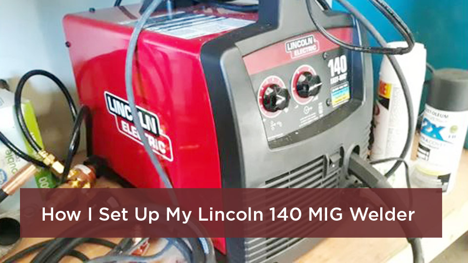
A worn, dirty, kinked, or incorrectly trimmed MIG gun liner can make the wire stutter, bird-nest at the drive rolls, or burn back into the contact tip. Replacing the liner is usually a straightforward maintenance job, but the trim length and retaining method are specific to the gun. The safest approach is to identify the exact gun model and follow its manual before cutting anything.
Quick Answer
To replace a MIG gun liner, disconnect the welder, close the gas supply, remove the required gun consumables, and lay the cable straight. Pull the old liner from the feeder end, insert the correct replacement, seat it fully, trim it to the gun maker’s specified length, deburr it, reassemble the gun, and test the wire feed on scrap.
Key Takeaways
- Match the liner to the gun model, cable length, wire type, and wire-diameter range printed by the manufacturer.
- Do not use a universal trim measurement. Different gun families use different liner stick-out or cut-off dimensions.
- Lay the cable straight, fully seat the liner, make a square cut, and remove every burr before reassembly.
- Do not put anti-spatter spray, silicone lubricant, penetrating oil, or threadlocker inside the liner unless the gun maker specifically requires it.
- After replacement, check the contact tip, drive-roll type and tension, spool brake, and cable routing before blaming the new liner.
At a Glance
| Time Required | Usually 15 to 30 minutes once you have the correct liner and trim instructions |
| Difficulty | Beginner to intermediate |
| Tools Needed | Gun manual, correct liner, sharp liner cutter or side cutters, the specified wrench or Allen key, trim gauge if supplied, gloves, and eye protection |
| Cost | One compatible replacement liner; cost varies by gun, length, liner design, and wire range |
The first time my MIG welder started sputtering, I blamed the spool, contact tip, and drive-roll tension. The liner was the real problem. That experience taught me to inspect the whole wire path instead of turning the tension knob tighter and hoping the feed improves.
A liner guides the electrode wire from the feeder through the gun cable and toward the contact tip. When the path is clean, correctly sized, and properly trimmed, the wire can move with steady resistance. When the liner is damaged or misinstalled, the drive rolls may keep pushing until the wire slips, stalls, or piles up behind the feeder.
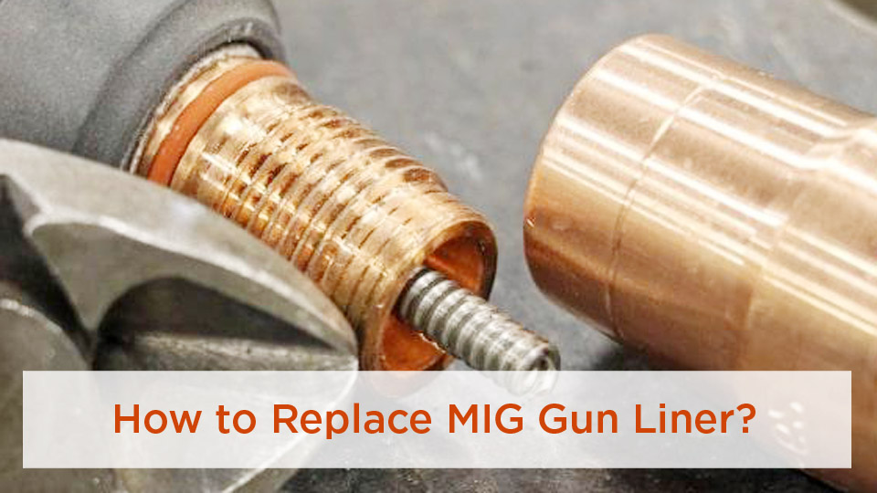
Image by thefabricator
What Is a MIG Gun Liner and Why Does It Wear Out?
A MIG gun liner is the replaceable guide inside the gun cable. It keeps the welding wire aligned between the feeder and the front-end consumables. A liner that is the wrong size, too short, too long, crushed by a set screw, or packed with wire shavings can create gaps and drag in the feed path.
Common conventional liners use a wound steel construction for many solid-steel, stainless-steel, and flux-cored wires. Aluminum and other soft wires usually need a gun system and low-friction plastic liner that the manufacturer approves for that wire. Some guns also use front-loading or two-piece liner systems, so the removal direction and trimming method may differ from a standard rear-loading liner.
Liners wear because the wire rubs against the inside surface. Abrasive flux-cored wire, rusty or dirty wire, excessive drive-roll pressure, sharp cable bends, crushed cables, and metal shavings all increase resistance. Heat and physical damage near the gun neck can also affect feeding, but you should confirm the entire path before assuming the liner alone caused the problem.
Note: A liner is not the same thing as a drive roll. V-groove, U-groove, and knurled designs describe drive rolls. In general, hard solid wires use the groove specified for solid wire, soft aluminum wire uses polished U-groove rolls, and many flux-cored wires use knurled rolls. Check the feeder manual for the exact combination.
Signs Your MIG Gun Liner May Need Replacement
Erratic feeding is the most common warning. The wire may surge, pause, chatter, or feed normally only when the cable is perfectly straight. Other signs include repeated bird-nesting, unexplained drive-roll slipping, burn-back at the contact tip, fine metal shavings near the feeder, and noticeably high resistance when the wire is pulled through the gun with the drive rolls released.
These symptoms do not prove that the liner is bad. A worn or undersized contact tip, the wrong drive-roll groove, too much or too little drive pressure, excessive spool-brake tension, a kinked cable, dirty wire, a blocked inlet guide, or incorrect welding settings can produce similar problems. Inspect the system in order instead of replacing random parts.
Pro Tip: Remove the contact tip and straighten the cable before checking feed resistance. If the wire feeds smoothly with the tip removed but binds after the tip goes back on, the tip may be damaged, contaminated, or the wrong size.
Choosing the Right MIG Gun Liner
Start with the gun make and model. Then match the liner series, cable length, wire material, and wire-diameter range. Do not choose a liner by a single inside-diameter number unless the gun maker uses that number in its parts chart. Many replacement liners are labeled as a wire range, such as .030 to .035 inch, rather than one universal bore size.
Length also matters. A liner made for a longer cable may be designed to be cut, while another system may use a fixed-length or front-loading replacement. A liner that is too short can leave a gap between components. A liner that is too long can buckle, compress, or prevent the front-end parts from seating correctly.
| Liner Family | Typical Use | Advantages | Important Limits |
|---|---|---|---|
| Steel spiral or wound-steel liner | Many solid-steel, stainless-steel, and flux-cored wires | Durable and abrasion-resistant | Not the usual choice for soft aluminum wire; must match the listed wire range |
| Plastic, nylon, PA, or PTFE-style liner | Aluminum and other soft wires when approved by the gun maker | Lower-friction path that reduces shaving of soft wire | Can be cut or crushed easily and may require a special guide, collet, or trim method |
| Front-loading or two-piece liner | Compatible guns designed for quick liner changes | Can reduce the amount of gun disassembly | Requires the correct retainer, gauge, and installation sequence |
| Specialty composite liner | Manufacturer-approved specialty wire applications | Designed for a specific feed problem or wire family | Do not assume it works with every wire or gun |
For professional work, the welding procedure still has to meet the applicable code or specification. A standard such as AWS D1.1 may govern structural-steel welding, but it does not give one universal liner cut length for every gun. The gun manufacturer’s instructions control the liner installation, while the approved welding procedure controls voltage, wire-feed speed, gas, wire, and joint requirements.
Products Worth Considering
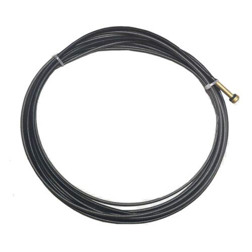
Lincoln Kp1937-3 Liner For .025 To .035 Wire Replacement

MIG gun liner for feeding .023-.035 diameter MIG welding wire

Tools and Materials You Need
- The exact replacement liner listed for your gun and wire range
- The gun owner’s manual or official liner-installation sheet
- A sharp liner cutter, side cutters, or the cutter specified by the manufacturer
- The correct wrench, nut driver, or Allen key for the gun
- The supplied trim gauge or liner guide, when the system uses one
- Eye protection and clean work gloves
- A new contact tip if the old one is worn, fused, enlarged, or contaminated
- A compliant safety blow gun only if the manufacturer allows compressed-air cleaning
Warning: Disconnect input power before opening the feeder or servicing the gun. Close the shielding-gas cylinder and relieve pressure according to the equipment manual. Never point welding wire or compressed air at your hand, face, or another person.
Do not spray anti-spatter compound, silicone lubricant, penetrating oil, or other chemicals into the liner unless the gun manufacturer specifically calls for that product. These materials can collect debris, damage some liner materials, or contaminate the wire path. Do not apply threadlocker to liner set screws unless the manual requires it.
Products Worth Considering

【LM3A-15 .035-.045 liner Perfect Compatibility】Fits for Miller AccuLock MDX-100, MDX-250 MIG welding gun, OEM replacement part number LM3A-15, mig gun liner ideal original liner replacement
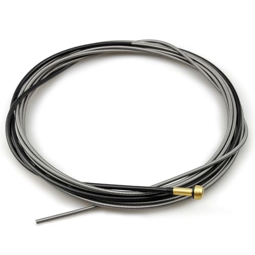
【Precise Fit for Lincoln Welding Guns】Specifically designed for Lincoln MIG guns, compatible for Magnum 100L, for Magnum PRO 100L/175L. Mig liner Directly replaces OEM part KP35-40-15, Mig liner kp1937-3 easy to install without extra modification

Miller style MIG gun liner (steel conduit) 194011
How to Replace a MIG Gun Liner Step by Step
The exact procedure varies by gun. The steps below cover a common rear-loading liner, followed by notes for front-loading systems. Read your manual before loosening the first fastener.
1. Identify the Gun, Liner, and Trim Specification
Find the model number on the gun, cable tag, power pin, or equipment parts list. Confirm the liner part number, supported wire range, cable length, removal direction, and trim dimension. Do this before removing the old liner because some guns use a trim gauge, some measure from the gun tube, and others trim the liner flush with a component.
There is no safe universal liner-trim number. Official Lincoln manuals, for example, show different cut dimensions and procedures for different Magnum gun and liner families.
2. Make the Welder Safe and Remove the Wire
Turn the machine off, unplug it or follow your shop’s lockout procedure, close the gas cylinder, and relieve the regulator pressure as directed by the manual. Release the drive-roll pressure. Cut the wire near the feeder and pull the used wire out from the gun end when the equipment maker recommends that method. Avoid dragging a dirty, bent, or oxidized wire end backward through the liner.
3. Lay the Gun Cable Straight
Place the gun and cable on a clean, flat surface with no loops, tight curves, or twists. Manufacturers repeatedly call for a straight cable during liner removal, insertion, and trimming because a bent cable changes how the liner sits inside the assembly.
4. Remove the Front-End Consumables Required by the Manual
Remove the nozzle and contact tip. Some guns also require removal of the diffuser, tip adapter, nozzle insulator, or gun-tube component. Use the correct tool so you do not crush the parts. Keep the pieces clean and in order.
5. Release and Remove the Old Liner
At the feeder end, loosen the liner nut, connector cap, bushing, or set screw specified by the manufacturer. Pull the liner out through the approved end of the cable. If it will not move, stop and check for another retainer. Do not flood the cable with penetrating oil or force the liner hard enough to damage the power cable or gas path.
Inspect the removed liner for kinks, flattened areas, rust, wire shavings, heat damage, and a cut end that is too short or heavily burred. The condition can help you find the original cause instead of repeating it with the new part.
6. Clean the Cable Only as the Manual Allows
Some gun manuals allow the empty cable conduit to be blown out gently with low or partial air pressure. In a workplace covered by OSHA, compressed air used for cleaning must comply with 29 CFR 1910.242(b), including pressure reduction, chip guarding, and personal protective equipment. Never use the 100 or 120 PSI shop-line pressure stated in the original draft.
If your manual does not call for air cleaning, wipe the accessible components and replace a contaminated liner. Do not push rods, loose wire, solvents, or abrasive material through the gun unless the manufacturer provides that procedure.
7. Insert and Fully Seat the New Liner
Feed the untrimmed liner into the end specified by the gun maker while the cable remains straight. Use steady, controlled pressure. If the liner binds, pull it back slightly and check alignment rather than forcing it. Fully seat the bushing or retainer against the connector before tightening the retaining part.
Tighten the liner nut or set screw only as directed. Several Lincoln gun manuals warn that overtightening can split or collapse the liner and cause poor feeding. Do not substitute a guessed torque value such as 10 to 15 ft-lb.
8. Trim the Liner to the Manufacturer’s Dimension
Keep the cable straight and use the supplied gauge, trim stick, or measurement point. Make one clean, square cut with the correct tool. Remove burrs without closing or deforming the opening. For a plastic liner, use the blade, bevel, or inner-tube trimming method specified by the liner instructions.
Note: Contact-tip recess or stick-out is not the same measurement as liner trim length. The original 1/8-inch solid-wire and 3/8-inch flux-core rule mixed two different setup details and should not be used to cut a liner.
You may compare the new liner with the old one as a rough check, but do not use the old liner as the final template. The old part may have been cut incorrectly, compressed, or installed in a different gun.
9. Reassemble the Gun and Reload Clean Wire
Reinstall the diffuser, tip adapter, contact tip, insulator, and nozzle in the order and tightness specified by the manual. Confirm that the liner ends meet the adjacent guides without a gap. Load clean, rust-free wire and verify that the contact tip and drive rolls match the wire size and type.
10. Set Drive Pressure and Test the Feed
Set spool-brake and drive-roll pressure using the welder manual. The rolls need enough force to feed without slipping, but excessive pressure can deform wire and worsen bird-nesting. Keep the gun pointed in a safe direction while jogging the wire. Never catch or stop the moving wire with your bare hand.
After the wire feeds smoothly, restore the gas supply and make a test weld on suitable scrap. Use the machine chart or qualified procedure for voltage, wire-feed speed, polarity, gas, and material thickness. Do not use one universal setting such as 20 volts and 300 IPM for every .035-inch wire and 1/4-inch plate application.
How Front-Loading Liners Differ
Some Bernard and Tregaskiss guns use a QUICK LOAD-style liner that can be replaced from the front after the system has been installed. The retainer, installation direction, liner guide, and trim gauge are part of that design. Follow the official QUICK LOAD liner instructions rather than applying the rear-loading procedure blindly.
Other modern systems lock or reference the liner at both ends to reduce gaps and measurement errors. A system-specific video or manual is more reliable than a generic trim dimension copied from another gun.
Common MIG Liner Replacement Mistakes
- Buying by wire diameter alone: The liner must also match the gun series, cable length, and liner design.
- Cutting before seating: A liner trimmed before the bushing is fully seated can end up too short.
- Trimming a curved cable: Cable bends can change the apparent length and create a gap after the cable straightens.
- Leaving a burr: A sharp or pinched cut can shave wire and increase drag.
- Overtightening a set screw: The screw can crush or collapse the liner.
- Using the wrong front-end parts: An incorrect contact tip or diffuser can create a restriction even when the liner is new.
- Adding lubricant or threadlocker without instructions: Unapproved chemicals can contaminate the feed path or make future service harder.
- Using high-pressure air: Excessive air can create a debris plug and may violate workplace cleaning rules.
- Turning drive pressure up to hide drag: More pressure can deform the wire and make a downstream restriction more destructive.
How to Maintain a MIG Gun Liner
Use clean, dry, rust-free wire and store spools where they cannot collect moisture and grinding dust. Keep the gun cable as straight as practical during welding and avoid wrapping excess cable tightly around the machine. Do not let carts, vehicles, or heavy workpieces run over the cable.
Inspect the contact tip, diffuser, feeder guides, drive rolls, and cable whenever feeding changes. Clean or replace the liner at the interval listed in the gun manual. Some manuals give an electrode-weight interval for a specific gun, while others say to service the liner as conditions require. There is no dependable universal rule such as every three to six months, every ten spools, or every week.
After each job, hang or coil the gun in broad loops instead of tight bends. Record liner replacements in a shop maintenance log if repeatability, quality control, or production downtime matters. Documentation helps you spot whether a certain wire, cable position, or operating area is shortening liner life.
Troubleshooting Wire Feed After a Liner Replacement
| Symptom | Likely Checks |
|---|---|
| Wire will not enter the gun | Confirm the liner bushing is seated, guides are aligned, the liner range matches the wire, and the cut end is open and burr-free. |
| Bird-nesting at the drive rolls | Look for a blocked or undersized tip, short liner gap, crushed liner, sharp cable bend, excessive drive pressure, or wrong drive-roll groove. |
| Burn-back into the contact tip | Check for intermittent feeding, a worn or wrong-size tip, cable drag, wire-feed speed, voltage, burn-back control, and stick-out. Do not automatically raise voltage. |
| Feed changes when the cable bends | Inspect for a kinked liner, damaged cable, liner that is too long or too short, and an unsupported long push path. |
| Aluminum wire shaves or buckles | Verify the approved plastic liner or spool/push-pull system, polished U-groove rolls, correct tip, clean wire, minimal cable bends, and light but adequate pressure. |
| Arc is still unstable | Check the work connection, contact tip, polarity, shielding gas, consumable seating, wire quality, and welding parameters before replacing the liner again. |
Miller notes that improper liner installation or trimming can contribute to bird-nesting, burn-back, and an erratic arc. Those same symptoms can also come from other restrictions, so work through the feed path from spool to contact tip.
Conclusion
Replacing a MIG gun liner is not difficult once you stop treating every gun the same. Match the liner to the gun and wire, disconnect the equipment, straighten the cable, seat the liner fully, and trim it with the measurement or gauge supplied for that model. A clean, gap-free wire path is more important than a guessed torque, pressure, or welding setting.
Listen to the machine, but verify the full feed system before blaming one part. Keep a correct spare liner and the gun’s trim instructions with your consumables. That small habit can turn an erratic feed problem into a controlled maintenance job instead of a long troubleshooting session.
Frequently Asked Questions
What size MIG liner do I need for .035-inch wire?
Use the liner part number or wire range listed for your exact gun. Many manufacturers sell a liner labeled for .030 to .035-inch wire, but you should not assume that every .035-inch wire needs a universal .052-inch bore. Gun design, liner construction, wire material, and cable length all matter.
How often should I replace my MIG gun liner?
Replace it when inspection or troubleshooting shows damage, contamination, excessive drag, or an incorrect cut. Follow any interval in the gun manual. Usage, wire type, cable routing, shop dust, and wire condition vary too much for one reliable calendar rule.
Can I reuse an old MIG liner after cleaning it?
You may reuse a serviceable liner if the manufacturer allows cleaning and the liner is not kinked, crushed, rusted, scored, shortened, or heavily contaminated. Replace it when damage is visible or feed resistance remains after approved cleaning.
Why is my new MIG liner kinking during installation?
The cable may be curved or twisted, the liner may be entering the wrong component, or the liner may not match the gun. Lay the cable straight, confirm the installation direction, and use controlled pressure. Stop if the liner binds instead of forcing it.
What is the difference between steel and nylon MIG liners?
Wound-steel liners are durable and commonly used with harder steel and flux-cored wires. Nylon, PA, PTFE-style, and other plastic liners provide a lower-friction path for soft aluminum wire when the gun maker approves them. The correct choice depends on the gun, wire, and feeding system.
Can I use the same liner for steel and aluminum wire?
Usually not without checking the equipment instructions. Aluminum often needs a dedicated low-friction liner, suitable drive rolls, a correct contact tip, and sometimes a spool gun or push-pull gun. Steel shavings left in a shared path can also contaminate aluminum wire.
How do I find the correct liner trim length?
Use the owner’s manual, official parts sheet, liner package instructions, or supplied trim gauge for the exact gun and liner series. Do not copy a measurement from a different gun or confuse contact-tip recess with liner trim length.
Sources
- Lincoln Electric Magnum PRO Curve HDE operator’s manual – model-specific liner seating, trimming, deburring, and overtightening warnings
- Bernard and Tregaskiss QUICK LOAD liner instructions – front-loading liner installation and gauge-based trimming
- Miller: How to Choose MIG Welding Consumables – liner installation, alignment, bird-nesting, burn-back, and erratic-arc prevention
- Miller: Common MIG Weld Defects – bird-nesting, burn-back, and broader wire-feed troubleshooting
- OSHA 29 CFR 1910.242 – compressed-air cleaning requirements
- Miller: Welding Operation Mistakes – manufacturer-recommended liner selection, installation, and trimming