I’ve seen new welders fight a flame that is too soft to form a steady puddle, then overcorrect until the tip pops, the joint oxidizes, or the sheet begins to warp. I made the same mistake when I learned to adjust an oxy-fuel welding torch: I treated the regulator numbers as the main target. The safer approach is to select the correct tip, follow its pressure chart, verify gas flow and cylinder capacity, and then tune the flame by sight and sound.
Quick Answer
To adjust an oxy-fuel welding torch, select the exact tip first, use its manufacturer pressure chart, inspect and leak-test the system, purge each hose separately, light the acetylene with a striker, and add oxygen until the inner cone is sharp and the acetylene feather disappears. Never use acetylene above 15 psig.
Key Takeaways
- There is no universal oxygen or acetylene pressure. Match the pressure to the exact torch, tip, fuel gas, metal thickness, hose setup, and manufacturer chart.
- Set and confirm working pressure while the appropriate torch valve is open and gas is flowing.
- A neutral flame has a clean, well-defined inner cone with no acetylene feather and no sharp oxidizing hiss.
- Acetylene must never be used above 15 psig, and a large heating tip must not exceed the cylinder’s safe withdrawal capacity.
- A pop is not a signal to turn a regulator at random. Shut down and inspect the tip, flow, connections, and safety devices.
- After a flashback, do not simply relight the torch. Shut down, cool the equipment, and have affected components inspected before reuse.
At a Glance
| Time Required | About 10–15 minutes for inspection, setup, purging, leak testing, and flame adjustment |
| Difficulty | Intermediate; supervised training is strongly recommended for first-time users |
| Tools Needed | Complete approved torch outfit, correct tip and tip chart, striker, approved leak-detection solution, proper tip cleaners, wrench, PPE, and suitable fire extinguisher |
| Cost | No added cost if the outfit and safety gear are already available; leak solution, tip cleaners, or worn replacement parts add variable cost |
Warning: Oxygen and fuel-gas equipment can cause fire, explosion, severe burns, or toxic-fume exposure when used incorrectly. Never use acetylene above 15 psig, never allow oil or grease on oxygen equipment, never leak-test with a flame, and do not operate a damaged or unfamiliar torch without qualified instruction.
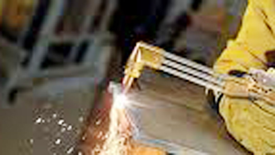
Image by ESAB.
Oxy-Fuel Welding Basics
Oxy-fuel welding, often called oxy-acetylene or gas welding, mixes oxygen with a compatible fuel gas to produce a concentrated flame. In fusion welding, that flame heats the joint edges until a puddle forms, and filler rod is added when the procedure requires it. The same basic outfit can also braze, heat, and—when fitted with the correct cutting attachment and tip—cut suitable steel.
That versatility is why I still value oxy-fuel equipment for field repairs, farm equipment, thin mild-steel work, heating seized parts, and jobs where electrical power is limited. It is slower than MIG on production work and puts more heat into a broad area than TIG, but it teaches heat control in a way few other processes do.
Oxy-fuel welding and oxy-fuel cutting are not the same operation. Welding melts and joins the base metal. Conventional oxy-fuel cutting preheats suitable steel and then uses a separate high-purity oxygen jet to oxidize and remove it. Because that cutting reaction depends on oxide behavior, conventional oxy-fuel cutting is mainly suited to mild steel and some low-alloy steels—not aluminum, stainless steel, or copper. ESAB explains these material limits in its oxy-fuel cutting overview.
Mild steel is the most forgiving material for learning flame control. Aluminum can be gas welded with the correct flux, filler, preparation, and a procedure suited to the alloy, but TIG or MIG is usually easier to control. Stainless steel normally calls for a properly specified TIG, MIG, or other qualified process rather than an improvised oxy-fuel setup. Back-purging may be required by some TIG pipe procedures, but it is not a generic oxy-fuel adjustment.
Essential Equipment for Oxy-Fuel Torches
A complete oxy-fuel outfit includes compatible oxygen and fuel-gas cylinders, regulators, hoses, approved protective devices, a torch handle, the correct welding or heating tip, and—when cutting—a compatible cutting attachment and cutting tip.
- Cylinders: Use only the intended gas, keep the cylinders secured, and protect them from impact, sparks, hot slag, and excessive heat.
- Regulators: Use a regulator designed and rated for the specific gas. Identify equipment by labels, fittings, and the manual—not by paint color alone.
- Hoses: In common U.S. service, oxygen and fuel hoses are distinguishable and are often green and red, but verify the hose markings. Never interchange them.
- Check valves: These help prevent reverse gas flow. They do not necessarily stop a flame front.
- Flashback arrestors: These are designed to stop flame propagation and may include additional shutoff or thermal functions. Use approved devices with adequate flow capacity in the locations specified by the torch manufacturer.
- Tips: Welding, heating, and cutting tips have different designs and gas demands. Use a tip made for the torch, mixer, fuel gas, and application.
- Igniter: Use an approved friction striker. Never use a cigarette lighter, match, or nearby hot work to light the torch.
For U.S. equipment, use the correct CGA connections and never force a mismatched fitting or defeat a left-hand/right-hand connection with an improvised adapter. Inspect sealing surfaces, O-rings where the design uses them, valve seats, threads, and tip seating areas. Do not apply oil, grease, ordinary pipe dope, or unapproved tape to oxygen fittings.
I became strict about check valves, flashback protection, and tip condition after seeing how quickly one overheated tip can turn a normal flame into repeated popping. Those devices add protection, but they do not replace the correct tip, pressure, gas flow, and operating sequence.
Products Worth Considering

Color-coded for gas service to provide added Safety

Gas Service: Oxy/Fuel Torch Mount Flashback Arrestors

Flashback arrestor set has internal check valves for both oxygen and acetylene. The check valve design allows the flashback arrestor to guarantee that gas can merely flow in one direction instead of back flow to prevent accidents.
Safety Precautions Before Adjusting Your Torch
Before touching the regulators, make the work area safe. OSHA’s general welding, cutting, and brazing requirements address fire prevention, eye protection, protective clothing, ventilation, confined spaces, and hazardous coatings.
Control Fire and Explosion Hazards
- Move the work to a designated hot-work area when possible.
- Remove combustible material from the spark and heat zone or protect it with suitable fire-resistant barriers.
- Check wall openings, floor openings, opposite sides of partitions, and areas below the work where sparks may travel.
- Keep a suitable extinguisher immediately available.
- Use a trained fire watch when the location or combustible exposure requires one. OSHA may require the watch to continue for at least 30 minutes after the work ends.
- Never weld, cut, braze, or heat a sealed vessel, tire and wheel assembly, pressurized part, or container that has held a flammable or toxic substance unless it has been properly cleaned, vented, tested, and authorized for hot work.
- Mark or guard hot metal after the flame is shut off.
Secure and Position the Cylinders
Keep cylinders upright and secured with a suitable cart, chain, or other approved restraint. Position them where sparks, flame, slag, and hot metal cannot reach them. Close cylinder valves when work is finished, when cylinders are empty, or before moving the outfit as required. OSHA’s gas-welding and cutting requirements provide detailed cylinder, hose, torch, and regulator safeguards.
Open cylinder valves slowly while standing to the side of the regulator, not in front of its gauges. A fuel-gas valve must remain quickly closable; under OSHA’s cited construction rule, it must not be opened more than 1½ turns. Leave the required valve wrench in place when the cylinder design uses one. Open an oxygen cylinder fully only when its valve and supplier instructions call for back-seating.
Use the Correct Eye and Body Protection
Wear safety-rated eye protection, leather gloves, flame-resistant clothing that covers exposed skin, non-melting trousers without cuffs, and sturdy leather footwear. Keep synthetic fabrics, loose clothing, oily gloves, and flammable products away from the work.
| Operation | Thickness | OSHA Minimum Filter Shade |
|---|---|---|
| Gas welding | Under 1/8 in. | 4 |
| Gas welding | 1/8–1/2 in. | 5 |
| Gas welding | Over 1/2 in. | 6 |
| Oxygen cutting | Under 1 in. | 3 |
| Oxygen cutting | 1–6 in. | 4 |
| Oxygen cutting | Over 6 in. | 5 |
These are minimum values from the OSHA filter-lens table. A darker shade may be used if it still provides a clear, safe view of the work.
Control Fumes and Coatings
Work with adequate general or local exhaust ventilation and keep your head out of the fume plume. Identify paint, galvanizing, plating, flux, filler metal, oil, and other surface contamination before heating. Zinc, lead, cadmium, chromium-containing material, fluorides, and unknown coatings may require specific ventilation, respiratory protection, or removal procedures. Oxygen must never be used as ventilation.
Note: A respirator is not a substitute for controlling the hazard. Workplace respirator use requires proper selection, medical evaluation, fit testing, and a compliant respiratory-protection program.
Step-by-Step Guide to Setting Up Your Oxy-Fuel Torch
Products Worth Considering

Drill-type tip cleaner

Long, oxy-acetylene tip cleaner

Include: 1pc 3"torch cleaner + 1pc 5"torch cleaner + 1pc torch striker+4pcs flint refills
1. Identify the Torch, Fuel Gas, and Exact Tip
Read the torch-handle, mixer, attachment, regulator, and tip markings. Confirm that every component is compatible with the chosen gas. A tip designed for acetylene may not operate correctly or safely with propane, propylene, or natural gas.
Select the tip from the manufacturer’s chart based on the job. For welding, the chart normally starts with base-metal thickness. For cutting, it uses material type and thickness. For heating, it also lists fuel consumption, which must be compared with the cylinder’s available withdrawal rate.
2. Inspect the Complete System
With both cylinder valves closed and regulator adjusting screws backed out, inspect the cylinders, valve outlets, regulators, gauges, hoses, fittings, check valves, flashback arrestors, torch valves, attachment, and tip.
- Remove damaged hoses, cracked fittings, leaking torch valves, damaged gauges, and questionable safety devices from service.
- Make sure the tip is clean, undamaged, correctly seated, and tightened only as the manufacturer directs.
- Use only the proper-size tip cleaner. Do not enlarge or deform an orifice.
- Keep oxygen equipment free of oil, grease, sealant, and oily fingerprints.
3. Connect Regulators, Hoses, Protective Devices, and Tip
Attach the correct oxygen regulator to the oxygen cylinder and the correct fuel regulator to the fuel cylinder. Connect the oxygen and fuel hoses to their matching regulator and torch connections. Install approved check valves and flashback protection in the configuration specified by the torch manufacturer.
Tighten fittings with the correct wrench where required, but do not use excess force. Brass threads and sealing surfaces can be damaged by overtightening.
4. Open the Cylinders Safely
- Verify that both torch valves are closed.
- Back both regulator adjusting screws out until they turn freely without spring pressure.
- Stand to the side of the regulator gauges.
- Open the oxygen cylinder valve slowly. Open it fully only when the valve design and supplier instructions require it.
- Open the acetylene or other fuel-gas valve slowly and only far enough to permit quick emergency closure. Do not exceed the applicable valve-opening limit.
- Watch for abnormal gauge movement, sound, odor, or leakage. Close the cylinder immediately if something is wrong.
5. Set the Working Pressure With Gas Flowing
Do not rely only on a pressure shown while the torch valves are closed. The pressure may fall when gas begins to flow.
- For oxygen, open the torch oxygen valve or follow the cutting-attachment procedure specified by the manufacturer.
- Turn the oxygen regulator adjusting screw in slowly until the delivery gauge shows the exact chart pressure while oxygen is flowing.
- Close the oxygen torch valve.
- Open the fuel-gas torch valve.
- Turn the fuel regulator adjusting screw in slowly until the exact chart pressure is shown while fuel is flowing.
- Close the fuel valve.
When setting a cutting tip, the preheat and cutting-oxygen circuits may require separate checks. Cutting-oxygen pressure is commonly confirmed while the cutting lever is fully depressed, but the exact valve sequence must come from the attachment manual.
Pro Tip: Photograph or print the correct tip chart and keep it with the torch cart. Pressure numbers copied from another brand, tip series, hose setup, or fuel gas may be wrong for your equipment.
6. Purge Each Hose Separately
Purge oxygen and fuel one at a time. Never open both gases together for purging.
- Open the oxygen torch valve and allow oxygen to flow for the manufacturer-specified time needed to clear that hose. Close it.
- Open the fuel-gas valve and purge that hose for the required time. Close it.
- Vent the gases into a safe, well-ventilated area away from sparks, flame, people, and combustible material.
Longer or larger hoses contain more volume and may require a longer purge than a short shop outfit. A fixed three- or five-second rule is not reliable for every setup.
7. Leak-Test Before Lighting
Apply an approved oxygen-compatible leak-detection solution to the cylinder connections, regulator fittings, hose connections, protective-device joints, torch connections, valves, and tip seat as appropriate. Expanding bubbles indicate a leak.
If a leak appears, close the cylinder valves, bleed the system, back out the regulator screws, and repair or replace the defective component. Repeat the test before lighting. Never search for a gas leak with a flame.
How to Light and Adjust the Flame
The following sequence describes a common acetylene welding or heating tip. Cutting attachments, injector torches, alternate fuels, and some manufacturers use different procedures, so the operating manual takes priority.
- Hold the torch in a safe direction with the tip clear of people, cylinders, hoses, and combustible material.
- Crack the acetylene torch valve slightly.
- Ignite the gas with an approved friction striker.
- Increase the acetylene flow gradually until heavy smoke disappears and the flame becomes stable. If the flame lifts away from the tip, reduce the valve slightly until it seats.
- Open the oxygen torch valve slowly.
- Continue adding oxygen until the pale acetylene feather at the end of the inner cone just disappears.
- Confirm that the inner cone is sharp and stable and that the flame does not have the short, pointed cone and hard hiss of an oxidizing flame.
A neutral flame is identified by its appearance and sound, not by setting both regulator gauges to the same number. Oxygen and fuel pressures may differ even when the flame is neutral.
I once used a pocket lighter instead of a striker and singed a glove. That was enough to end the shortcut permanently. A striker keeps the hand farther from the tip and avoids carrying an open-flame lighter around hot work.
Warning: If the torch gives a high-pitched squeal, whistle, or sustained hissing sound, the flame may be burning inside the torch. Follow the manufacturer’s emergency shutdown sequence immediately. Do not relight the torch until it and the affected hoses and safety devices have been inspected.
Types of Flames and When to Use Them
Neutral Flame
A neutral oxy-acetylene flame has a well-defined blue inner cone without a visible acetylene feather. It is the normal starting point for mild-steel welding, many brazing operations, and the preheat flames of many acetylene cutting tips.
Carburizing or Reducing Flame
A carburizing flame contains excess acetylene and shows a secondary feather extending beyond the inner cone. It creates a reducing atmosphere and may be specified for selected brazing, hardfacing, aluminum, or specialty procedures. It should not be treated as a universal setting for high-carbon steel.
Oxidizing Flame
An oxidizing flame contains excess oxygen. Its inner cone becomes shorter and more pointed, and the flame develops a sharper hiss. Selected copper-alloy or specialty procedures may call for it, but it can oxidize mild-steel weld metal and is not the normal setting for general steel welding.
The flame used to preheat steel for cutting should not be confused with the cutting-oxygen jet. Pressing the cutting lever releases a separate oxygen stream that drives the oxidation reaction through the steel.
Temperature values for flame types are only approximate because the measured temperature changes with gas ratio, tip, flow, and the location in the flame. Adjust by the required flame characteristics and procedure—not by trying to assign an exact temperature to the color.
Recommended Pressure Settings for Different Tasks
There is no single pressure table that safely covers every oxy-fuel torch. ESAB’s pressure-selection guidance directs users to the manufacturer’s recommendations for the selected consumable, tip, and application.
| Task | What Determines the Pressure | Safe Adjustment Method |
|---|---|---|
| Thin-sheet welding | Metal thickness, alloy, welding-tip model, mixer, and hose setup | Choose the chart-listed tip and set both gases to that tip’s flowing-pressure values. |
| Oxy-fuel cutting | Steel thickness, cutting-tip family, fuel gas, hose length, and torch design | Set preheat gases as directed and confirm cutting-oxygen pressure with the lever depressed when the manual requires it. |
| Rosebud or multi-flame heating | Heating-tip model, required gas volume, cylinder size, duty cycle, and withdrawal capacity | Use the tip chart and verify that the fuel cylinder or approved manifold can supply the listed cubic feet per hour. |
| Brazing | Joint size, base metal, filler alloy, flux, and tip | Use the filler and torch manufacturers’ procedures; heat the joint evenly rather than chasing a generic PSI value. |
Pressure is only half of the setup. The tip must also receive enough gas volume from the cylinder and hoses to maintain that pressure safely while flowing.
OSHA 1910.253 states that acetylene must not be utilized above 15 psig. That is an absolute ceiling, not a normal target.
Large heating tips create another limit: cylinder withdrawal capacity. OSHA’s acetylene standard incorporates CGA G-1-2009 for cylinder handling and use. Compare the tip’s listed fuel consumption with current cylinder-supplier guidance. If one cylinder cannot supply the required flow, use a properly designed larger supply, an approved manifold, or a compatible alternate fuel and tip rather than raising the regulator pressure.
Backfire, Sustained Backfire, and Flashback
| Condition | What You Notice | Response |
|---|---|---|
| Backfire | A single pop, often followed by the flame going out | Close the torch valves, allow the tip to cool, and inspect for tip contact, overheating, dirt, damage, or incorrect flow. |
| Sustained backfire | Repeated popping or flame burning at or inside the tip | Shut down immediately. Inspect the tip, mixer, valves, pressure, gas supply, and connections before reuse. |
| Flashback | High-pitched squeal, whistle, or hiss as flame travels into the torch or hose system | Use the manufacturer’s emergency shutdown sequence, close the cylinder supply, cool the equipment, and remove affected components from service for inspection. |
Common backfire causes include touching the tip to the work, an overheated tip, a clogged or damaged orifice, a loose tip, low gas flow, a pressure drop caused by excessive tip demand, or incorrect lighting technique. Flashback may also involve reverse flow, damaged check valves, an internal leak, or a failed protective device.
If a hose or cylinder becomes involved in fire, warn others, evacuate the danger area, call emergency services, and follow the facility emergency plan. Do not approach a heated or fire-exposed cylinder.
Common Mistakes in Torch Adjustment and How to Fix Them
Using Pressure Numbers From Another Torch
Problem: The operator copies a setting from a video or another brand.
Fix: Use the exact chart for the torch, mixer, tip, and fuel gas in front of you.
Setting Pressure With the Torch Closed
Problem: The delivery gauge looks correct until the valve opens, then pressure drops.
Fix: Set and confirm the required working pressure with the applicable gas flowing.
Skipping the Purge or Purging Both Gases Together
Problem: Air or a mixed-gas pocket remains in the hose.
Fix: Purge each hose separately for the manufacturer-specified duration.
Lighting With the Wrong Sequence
Problem: The operator treats every welding tip, cutting attachment, and fuel gas the same.
Fix: Follow the manual for that equipment. For a common acetylene welding tip, fuel is normally lit with a striker before oxygen is added.
Using a Dirty or Damaged Tip
Problem: The flame is uneven, wanders, whistles, or pops.
Fix: Shut down, cool the tip, and clean it with the correct-size tool. Replace a tip with enlarged, distorted, cracked, or damaged orifices.
Turning Up Pressure to Fix Every Weak Flame
Problem: A restricted tip, undersized cylinder, long hose, failing regulator, or excessive gas demand is mistaken for a low setting.
Fix: Compare the complete setup with the tip chart and inspect the gas-supply path rather than turning the screw blindly.
Ignoring Regulator Creep
Problem: Delivery pressure rises after flow stops, which may indicate a leaking regulator seat.
Fix: Close the cylinder, bleed the system, and remove the regulator from service for manufacturer-authorized inspection or repair.
Using a Calendar-Based Service Rule Without the Manual
Problem: “Calibrate it yearly” is treated as universal.
Fix: Inspect before use and follow the equipment manufacturer, employer, and applicable standard for test, service, and replacement intervals.
How to Shut Down and Depressurize the Torch
Normal flame-extinguishing order can differ by torch design. For common Victor-style equipment, ESAB describes closing the torch oxygen valve and then the fuel valve. Follow the procedure printed in your own torch manual if it specifies a different order.
- Extinguish the flame using the torch-valve order required by the manufacturer.
- Close the oxygen and fuel-gas cylinder valves.
- Open the oxygen torch valve and allow the line and regulator pressure to fall to zero. Close the valve.
- Open the fuel-gas torch valve and allow that line and regulator to fall to zero. Close the valve.
- Back both regulator adjusting screws out until spring pressure is released.
- Verify that the delivery gauges read zero.
- Allow the torch, tips, and workpiece to cool in a fire-safe location.
- Inspect the equipment before storage and coil hoses without sharp bends or kinks.
ESAB also summarizes inspection, leak testing, striker use, shutdown, and depressurization in its oxy-fuel safety checklist.
Pros and Cons of Oxy-Fuel Welding Compared to Other Processes
Oxy-fuel equipment remains useful because it does not require welding electricity at the torch and can weld, braze, heat, and cut suitable steel with one outfit. It is portable, relatively simple, and especially helpful for repair work and controlled heating.
The tradeoffs are speed, heat input, distortion, gas handling, and a narrower practical material range for cutting. MIG is normally faster for shop production. TIG gives more precise heat and shielding control on stainless steel and aluminum. Stick welding often handles outdoor structural repair and surface contamination better than gas welding.
| Process | Strengths | Limitations |
|---|---|---|
| Oxy-fuel | Portable, versatile, excellent for heating, brazing, cutting suitable steel, and learning puddle control | Slower welding speed, broad heat-affected area, cylinder handling, and greater distortion risk |
| MIG | Fast, productive, and easy to automate | Needs electrical power, wire feeding, and suitable shielding conditions |
| TIG | Precise control and strong material coverage, including stainless and aluminum | Slower and more skill-intensive; requires power and shielding gas |
| Stick | Good field portability and tolerance for wind and less-than-perfect surfaces | More slag and spatter; harder to use on very thin sheet |
In my own fabrication work, oxy-fuel is still a strong field and repair tool, while MIG handles most repetitive shop welding and TIG handles jobs that need tighter heat and shielding control.
Comparison Table of Flame Types
Use this table as a visual guide, then confirm the required flame in the welding, brazing, or heating procedure.
| Flame Type | Characteristics | Temperature Guidance | Best For | Advantages | Risks and Limits |
|---|---|---|---|---|---|
| Neutral | Sharp blue inner cone; no acetylene feather; stable sound | High-temperature oxy-acetylene flame; exact value varies by ratio, tip, flow, and measurement point | Most mild-steel welding, many brazing jobs, and cutting-tip preheat | Balanced starting point with limited oxidation or carbon addition | Still requires the correct tip, pressure, travel speed, and procedure |
| Carburizing or reducing | Visible acetylene feather beyond the inner cone | Not safely identified by a fixed temperature number | Selected brazing, hardfacing, aluminum, and specialty procedures | Creates a reducing atmosphere | Can add carbon, produce soot, or damage unsuitable weld metal |
| Oxidizing | Shorter pointed cone with a sharper hiss | Not safely identified by a fixed temperature number | Selected copper-alloy and specialty procedures when specified | Concentrated flame characteristic for limited applications | Can oxidize mild-steel weld metal and impair weld quality |
Learn the flame by sight and sound on clean scrap under supervision. The metal response should confirm the setting, but it should never replace the tip chart or qualified procedure.
Material and Process Limits
Mild and Low-Carbon Steel
This is the most common material for learning oxy-acetylene welding and conventional oxy-fuel cutting. A neutral flame is normally the starting point for welding, while cutting uses preheat flames plus a separate cutting-oxygen jet.
High-Carbon and Alloy Steel
These materials may harden, crack, or lose properties when heated and cooled incorrectly. Do not assume a carburizing flame prevents brittleness. Follow an approved procedure covering preheat, interpass temperature, filler metal, and cooling.
Aluminum
Oxy-fuel welding is possible with suitable alloy preparation, flux, filler, and flame control, but the oxide layer and lack of color change before melting make it difficult. TIG or MIG is usually the more practical choice. Do not copy a generic pressure range across tip brands.
Stainless Steel
Oxy-fuel is generally not the preferred fusion-welding process for stainless steel because shielding, oxidation, contamination, and heat input are difficult to control. Food-grade or code-regulated stainless work should use the specified qualified procedure—commonly TIG or MIG—not an improvised carburizing flame.
Copper and Brass
These metals conduct heat rapidly, and zinc-bearing brass can release hazardous fumes when overheated. Select the flame, filler, flux, and ventilation from the alloy and filler manufacturer’s procedure. Do not assume one flame type fits every copper alloy.
Painted, Galvanized, Plated, or Unknown Metal
Do not heat an unknown coating until it has been identified. Remove coatings by an approved method where required and provide the ventilation or respiratory controls specified for the hazard. Burning paint, zinc, lead, cadmium, and other coatings can produce dangerous fumes.
Real-World Applications in Shops, Homes, and Job Sites
In a home shop, oxy-fuel can repair a clean mild-steel bracket or lawn-equipment frame when the joint design and material are suitable. The correct approach is not simply “low pressure for thin metal”; it is the chart-listed tip and working pressure, followed by careful travel speed and heat control.
On job sites, a cutting attachment can sever suitable steel, trim rebar, prepare plate edges, or heat a seized component. Cylinders must remain secured and protected from sparks and vehicle traffic, and the site’s hot-work permit and fire-watch rules still apply.
A rosebud can heat a large area for bending or straightening, but it may consume more acetylene than one small cylinder can safely provide. I now check the tip’s fuel-demand rating before opening a regulator. If the cylinder cannot support it, the answer is a properly designed gas supply or compatible alternate-fuel setup—not more pressure.
For students, clean mild-steel tee and butt joints are useful practice pieces. Focus on maintaining a stable neutral flame, holding a consistent cone-to-work distance, forming the puddle without overheating the edges, and feeding filler smoothly.
For stainless exhaust, sanitary tubing, aluminum, or critical structural work, choose the process and qualified procedure first. A torch is versatile, but versatility does not make every application appropriate.
Note: Practice should be done on known, clean material in a fire-safe area with supervision. Do not use pressure vessels, wheels, fuel containers, galvanized scrap, or unidentified coated metal as practice pieces.
Conclusion
Properly adjusting an oxy-fuel torch starts before the flame is lit. Identify the equipment, select the exact tip, inspect the system, use approved protective devices, set the manufacturer’s working pressure while gas is flowing, purge each line separately, and leak-test every connection. Then light with a striker and add oxygen until the required flame is stable.
The most important habits are simple: never exceed 15 psig acetylene, never guess at pressure or tip capacity, keep oxygen equipment free of oil, and stop when the torch pops, whistles, leaks, or behaves differently than expected. A careful setup takes only a few extra minutes and produces a safer flame, more predictable heat, and better work.
Frequently Asked Questions
What PSI should I set for oxy-acetylene cutting?
There is no universal cutting pressure. Identify the cutting-tip manufacturer, tip family, tip size, steel thickness, fuel gas, and hose setup, then use that exact chart. Confirm cutting-oxygen pressure with the lever depressed when the manual requires it. Acetylene must never be used above 15 psig.
How do I know if my oxy-fuel flame is neutral?
A neutral oxy-acetylene flame has a sharp, stable blue inner cone and no visible acetylene feather. It should not have the short pointed cone and sharp hiss of an oxidizing flame. Equal flame balance does not mean the two regulator gauges must show equal pressure.
Why does my oxy-fuel torch pop or backfire?
Common causes include touching the tip to the work, an overheated or dirty tip, a loose or damaged tip, low gas flow, incorrect pressure, an undersized fuel supply, or an improper lighting sequence. Shut down, cool the equipment, inspect it, and confirm the exact tip-chart settings before relighting.
Can I use oxy-fuel for aluminum welding?
Yes, aluminum can be gas welded with the correct alloy preparation, filler, flux, tip, and trained flame control. It is difficult because aluminum’s oxide melts at a much higher temperature than the base metal and the metal gives little visual warning before melting. TIG or MIG is usually easier and more controllable.
What is the difference between welding and cutting tips on an oxy-fuel torch?
A welding tip mixes and burns oxygen and fuel through one flame outlet to heat and melt the joint. A cutting tip has preheat-flame ports surrounding a separate central cutting-oxygen passage. The cutting jet oxidizes and removes heated steel when the lever is pressed.
Should I set regulator pressure with the torch valve open?
Normally, yes. The final working pressure should be confirmed while the applicable gas is flowing because the gauge reading may drop after a torch valve opens. Follow the equipment manual for the exact valve sequence, especially when setting a cutting attachment.
What should I do if the torch has a flashback?
Use the manufacturer’s emergency shutdown sequence immediately, close the cylinder supply, and allow the equipment to cool. Do not relight it. The torch, hoses, check valves, flashback arrestors, and related fittings should be inspected, tested, or replaced as required before the outfit returns to service.
Which torch valve should I close first during shutdown?
Use the shutdown order specified by the torch manufacturer. Common Victor-style guidance closes the torch oxygen valve and then the fuel valve, but other equipment may specify a different order. After extinguishing the flame, close both cylinder valves, bleed each line separately, and back out the regulator adjusting screws.
Do I need both check valves and flashback arrestors?
They perform different protective functions. A check valve helps prevent reverse flow, while a flashback arrestor is designed to stop a flame front and may include other shutoff features. Use approved devices with adequate flow capacity in the configuration and locations specified by the torch manufacturer and applicable workplace rules.
Sources
- OSHA 29 CFR 1910.253 — Oxygen-Fuel Gas Welding and Cutting — acetylene pressure, approved equipment, and protective-system requirements
- OSHA 29 CFR 1926.350 — Gas Welding and Cutting — cylinders, hoses, torches, regulators, valve opening, and oil-and-grease precautions
- OSHA 29 CFR 1910.252 — General Welding, Cutting, and Brazing Requirements — fire prevention, PPE, ventilation, confined spaces, and hazardous materials
- OSHA 29 CFR 1910.133 — Eye and Face Protection — minimum filter-shade guidance for gas welding and oxygen cutting
- OSHA 29 CFR 1910.102 — Acetylene — incorporated CGA guidance for acetylene-cylinder handling and use
- ESAB — Mastering Pressure Selection for Oxy-Fuel Cutting and Welding — manufacturer-chart selection by tip, material thickness, equipment, and application