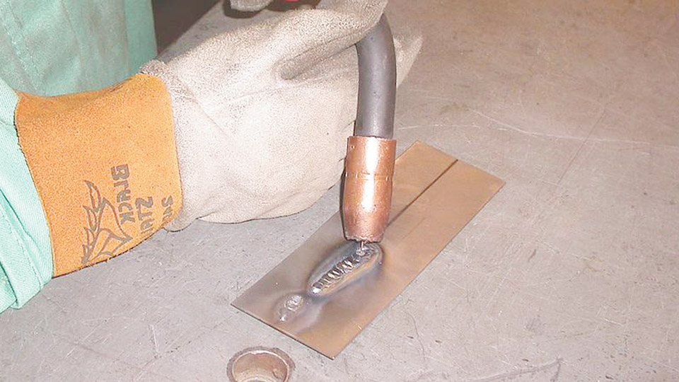
I can’t count how many times I’ve been in the middle of a MIG weld, thinking everything was set up correctly, only to see spatter everywhere, weak fusion, or a birdnest forming at the wire feeder. One of my earliest problems came while welding a thin car panel. I increased the settings because I assumed more heat meant more strength, but the result was burn-through and a lot of unnecessary repair work.
That experience taught me that MIG welding problems rarely come from one setting alone. Metal thickness, joint preparation, polarity, wire diameter, drive-roll setup, shielding gas, gun angle, travel speed, and work-lead contact all affect the arc. The right solution also changes when you compare MIG vs TIG welding, solid-wire GMAW, gas-shielded flux-cored welding, and self-shielded flux-cored welding.
This guide walks you through the most common MIG welding problems and solutions in a safe diagnostic order. You’ll learn what each defect looks like, which checks to make first, what to adjust, and when a weld needs to be removed or inspected by a qualified professional.
Quick Answer
Most MIG welding problems come from five areas: an unsafe or dirty setup, wrong polarity or gas, poor wire feeding, mismatched voltage and wire speed, or incorrect technique. Check the gas, work lead, consumables, polarity, and wire path first. Then use the machine chart and test one adjustment at a time on matching scrap.
Key Takeaways
- Do not change several settings at once. Find the first failed link in the setup and correct one variable at a time.
- Start with the machine’s door chart, manual, consumable data sheet, or welding procedure instead of copying universal voltage and wire-speed numbers.
- Porosity usually points toward shielding or contamination, while erratic sputtering often points toward wire feeding, polarity, voltage balance, or poor electrical contact.
- A weld can look smooth and still have incomplete fusion or shallow penetration underneath.
- Structural, pressure-containing, lifting, vehicle-safety, and other critical repairs require the applicable qualified procedure and inspection.
At a Glance
| Time Required | About 15–45 minutes for basic diagnosis; repair and inspection time varies with the defect and application. |
| Difficulty | Beginner to intermediate for practice pieces; advanced or professionally controlled for code and safety-critical work. |
| Tools Needed | Welder manual or door chart, PPE, matching scrap, wire brush or grinder, degreaser, pliers, contact-tip tools, flowmeter or purge function, and inspection light. |
| Cost | Often no added cost if the problem is setup or technique. A damaged tip, nozzle, liner, drive roll, gas hose, wire spool, or regulator may need replacement. |
Warning: Welding exposes you to arc radiation, hot metal, sparks, fumes, electricity, and compressed gas. Use suitable PPE, ventilation, fire controls, and the equipment manufacturer’s instructions. Never weld an unknown container, coated metal with unidentified hazards, or a safety-critical component without the required procedure and qualifications. Keep your hands away from the contact tip and moving wire during energized tests.
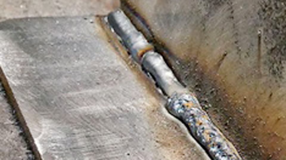
Image: Common MIG welding problems and troubleshooting solutions.
Start With Welding Safety and a Known Baseline
Before you diagnose the bead, make the work area safe. Remove combustible material from the spark path, keep suitable fire-extinguishing equipment available, and inspect nearby walls, floors, gaps, and concealed spaces. In workplaces covered by U.S. general-industry rules, OSHA 1910.252 includes fire-prevention, ventilation, cylinder, and hot-work requirements.
Wear a correctly rated welding helmet, safety glasses, flame-resistant clothing, welding gloves, and suitable footwear. Protect anyone nearby with screens or barriers. Keep cylinders upright and secured, protect the valve, and keep hoses away from sparks and hot metal.
Position ventilation so it draws fumes away from your breathing zone without pulling the shielding gas away from the weld. NIOSH recommends general or local exhaust controls and warns that working outdoors does not automatically guarantee adequate ventilation. Respiratory protection may be needed when other controls cannot reduce exposure sufficiently, but workplace respirators must be selected and used through an appropriate respiratory-protection program.
- Identify the base metal and every coating before striking an arc.
- Remove oil, grease, moisture, paint, rust, scale, and plating from the weld area as the procedure requires.
- Confirm the machine input power, duty cycle, polarity, wire classification, gas, and material range.
- Inspect the gun, cable, work lead, gas hose, regulator, and cylinder before troubleshooting.
- Do not troubleshoot a pressure vessel, fuel container, lifting device, structural member, suspension component, or rollover structure as a casual practice project.
Note: A discontinuity is not automatically a rejectable defect. Acceptance depends on the applicable drawing, welding procedure, code, contract, service conditions, and inspection criteria.
A Fast MIG Welding Troubleshooting Checklist
When a weld looks wrong, resist the urge to turn every knob. The fastest approach is to return the system to a known baseline and inspect it in order.
- Stop and make the area safe. Let the work cool, isolate power before opening the feeder, and close the cylinder valve when servicing the gas system.
- Confirm the process and polarity. Solid-wire MIG commonly uses electrode-positive polarity, while many self-shielded flux-cored wires use electrode-negative. Some wires differ, so follow the label and machine chart.
- Verify the shielding system. Confirm that the correct gas is connected, the cylinder contains gas, the valve is open, the flowmeter responds, the nozzle is clear, and hoses are not leaking or kinked.
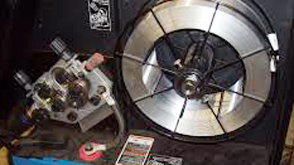
- Inspect the wire path. Check spool drag, drive-roll groove, roll pressure, liner size, contact-tip size, gun-cable bends, and wire condition.
- Clean the joint and work-lead location. Clamp to clean bare metal as close to the weld as practical.
- Return to the recommended settings. Use the machine’s chart, manual, WPS, or consumable data sheet for the actual wire diameter, gas, thickness, position, and joint.
- Test on matching scrap. Use the same material, thickness, joint, orientation, and fit-up when possible.
- Change one variable at a time. Record what you changed and what the bead did.
| Symptom | Likely Areas to Check | First Action |
|---|---|---|
| Pinholes or gas pockets | Gas coverage, leaks, drafts, contamination, excess stickout | Clean the joint and inspect the complete shielding path |
| Heavy spatter | Voltage/wire-speed balance, polarity, gas, stickout, transfer mode | Return to the chart settings and verify polarity |
| Wire stubs into the plate | Voltage too low for wire speed, poor work connection, erratic feeding | Check the work lead and restore the recommended parameter balance |
| Wire burns back into the tip | Wire feed interruption, excessive voltage, restricted liner, worn tip | Isolate power and inspect the tip, liner, rolls, and spool |
| Rope-like bead | Cold settings, excessive travel speed, poor toe fusion | Check wire speed, voltage, and travel against the machine chart |
| Wide, flat, undercut bead | Excess voltage, long arc, poor angle, excessive travel speed | Correct arc length and keep the puddle under control |
| Burn-through | Excess heat, poor fit-up, slow travel, oversized wire | Reduce heat input and use short, separated welds |
| Birdnesting | Blocked liner, over-tight rolls, tip seizure, excessive spool drag | Stop, isolate power, cut out the tangle, and inspect the feed path |
Read the Arc Before You Change the Settings
Arc sound can help, but only after you identify the transfer mode. A stable short-circuit transfer normally has an even, rapid crackling sound. Globular transfer tends to sound rougher and usually creates more spatter. Spray transfer produces more of a steady hum or buzz and requires the correct argon-rich gas, current range, wire, position, and material thickness.
The sound is only one clue. Watch the puddle, wire behavior, bead shape, toe wetting, and arc position. A smooth sound does not prove that the root fused, and a noisy arc may come from polarity, a poor work connection, unstable feeding, contamination, or a mismatched voltage-to-wire-speed relationship.
The Miller GMAW guide illustrates transfer modes and common troubleshooting patterns. Use it as general education, then follow the instructions for your specific machine and wire.
Common Porosity Problems in MIG Welding
Porosity appears as pinholes, bubbles, or cavities in or beneath the weld metal. Gas becomes trapped as the weld solidifies. Surface holes may be visible immediately, but internal porosity can remain hidden until the weld is tested or inspected.
I learned this lesson while working on an exhaust repair. A small amount of oil remained near the joint, vaporized under the arc, and left enough porosity to ruin the seal. Grinding out the affected weld and cleaning the area properly took much longer than the original preparation would have.
Common Causes of Porosity
- Insufficient shielding-gas coverage
- An empty or nearly empty cylinder
- Leaks, restrictions, or damaged O-rings in the gas path
- Drafts from fans, doors, wind, or poorly positioned extraction
- A nozzle clogged with spatter
- Excessive gun angle or wire extension
- Oil, grease, moisture, paint, rust, scale, or plating
- Wet, rusty, or contaminated wire
- The wrong gas for the wire and material
- Excessive gas flow that creates turbulence and draws air into the shielding envelope
How to Fix Porosity
- Remove the defective metal. Do not simply cover visible holes with another pass.
- Clean the joint. Use the preparation method allowed for the base metal and coating.
- Check the gas source. Confirm the correct gas, cylinder level, valve position, regulator, and flowmeter.
- Check for leaks. Inspect connections, hoses, gun seals, and fittings using the manufacturer’s approved method.
- Clean the nozzle. Make sure spatter is not disrupting the gas pattern.
- Control drafts. Shield the arc without creating an enclosed fume hazard.
- Correct the gun position. Keep the recommended contact-tip-to-work distance and a modest travel angle.
- Test on clean scrap. If the problem continues, isolate the gas system, gun, wire, and machine one component at a time.
Do not pull the trigger and place your hand near the contact tip to “feel” the gas. Use the gas-purge function when the machine has one. If it does not, follow the manual’s approved test procedure.
Pro Tip: Store wire in a clean, dry place and cover the machine between jobs. Rust or shop contamination on the wire can travel through the liner and create both feeding and weld-quality problems.
During one farm repair, porosity kept returning even after the joint was cleaned. The cylinder was almost empty and the gas delivery had become unreliable. Replacing the cylinder restored stable shielding. The lesson was to check the complete system instead of assuming the metal was still dirty.
Fixing Excessive Spatter in MIG Welds
Spatter is the scattering of molten droplets around the bead. Some spatter is normal in short-circuit and globular transfer, but heavy spatter signals a setup, parameter, or technique problem. It also adds cleanup time and can become trapped between passes if the surface is not cleaned.
What Causes Excessive Spatter?
- Wire feed speed that is too high for the selected voltage
- Voltage that is too high or too low for the operating point
- Wrong polarity
- Incorrect shielding gas or poor gas coverage
- Globular transfer when a different transfer mode is required
- Excessive wire extension
- Rusty or contaminated wire
- Oil, paint, rust, moisture, or scale on the workpiece
- A worn or incorrect contact tip
- Erratic wire feeding
- A poor work-lead connection
On an early gate project, I assumed spatter meant the voltage was always too high. Lowering it without checking wire speed made the wire stub harder into the plate. The correct fix was to return to the chart values and balance voltage and wire feed together.
How to Reduce Spatter
- Verify polarity and shielding gas against the wire label.
- Clean the workpiece and work-lead contact point.
- Inspect the wire, tip, nozzle, liner, and drive rolls.
- Return to the machine’s recommended starting settings.
- Keep the wire extension within the consumable maker’s range.
- Use a steady travel speed and keep the arc at the intended part of the puddle.
- Fine-tune voltage and wire feed in small steps on matching scrap.
For one railing job, moving from .035-inch wire to .030-inch wire gave the machine a more suitable operating range for the material. Spatter decreased, but the improvement came from matching the entire setup, not because a smaller wire is always better. Use the correct welding wire size for the machine, thickness, joint, and required deposition rate.
Listen for the expected sound of your transfer mode. Short-circuit transfer should normally produce an even crackle rather than a random series of violent pops. Spray transfer produces a smoother hum or buzz.
Anti-spatter spray or gel may reduce adhesion, but it should never be used to hide an unstable arc.
| Potential Benefit | Limitation or Risk |
|---|---|
| Reduces the time needed to remove adhered droplets | Does not correct wrong polarity, poor feeding, bad gas coverage, or incorrect settings |
| Helps protect the nozzle from heavy buildup | Excess product can contaminate the joint or interfere with later coating |
| Can protect nearby non-weld surfaces when the product is suitable | The safety data sheet may require ventilation and handling precautions |
Tackling Lack of Fusion in MIG Welding
Lack of fusion means the weld metal did not fuse completely to the base metal or a previous bead. Cold lap is closely related but often appears as weld metal rolling onto the surface without properly tying into the toe. Both can look acceptable from above while leaving a weak interface underneath.
On a pressure-vessel training mock-up, a smooth-looking bead failed inspection because one sidewall had not fused. That experience made one point clear: appearance alone cannot qualify a safety-critical weld.
Common Causes
- Insufficient heat for the joint and material
- Incorrect work or travel angle
- The arc trailing behind the puddle
- Travel speed that is too fast to melt the joint
- Travel speed that is too slow, allowing the puddle to run ahead of the arc
- Joint preparation that blocks access to the root or sidewall
- Scale, rust, paint, or other contamination
- An oversized weave without enough sidewall control
How to Improve Fusion
- Clean the joint and expose sound base metal.
- Verify the joint design, root opening, bevel, and fit-up.
- Use the machine chart or WPS to establish enough heat input.
- Keep the arc on the leading edge of the puddle.
- Use a work angle that directs heat into both members.
- Keep the travel angle modest unless the procedure specifies otherwise.
- Use stringer beads or a controlled weave that gives the arc access to each sidewall.
- Remove the failed weld completely before making a qualified repair.
While coaching a new welder, I noticed he was dragging the gun with the arc buried behind a large puddle. Changing to a controlled push angle helped him see the leading edge and improve toe fusion. A push technique is common for solid-wire GMAW, while many flux-cored wires are used with a drag technique. Follow the wire manufacturer’s instructions.
Note: A shop break test can help you compare practice settings, but it does not replace a qualified procedure, bend test, macroetch, nondestructive examination, or code inspection.
How Lack of Fusion Differs From Lack of Penetration
Lack of fusion and lack of penetration are related but not identical:
- Lack of fusion occurs when weld metal fails to join properly with a sidewall, base-metal surface, or previous bead.
- Lack of penetration means the weld does not extend deeply enough into the joint root or required depth.
- Overlap occurs when metal rolls over the toe without fusing.
- Excessive penetration occurs when too much weld metal melts through or protrudes excessively at the root.
A higher setting alone does not solve every case. Joint access, land thickness, root opening, wire extension, arc position, travel speed, position, and procedure all matter.
How to Prevent Burn-Through on Thin Materials
Burn-through happens when the arc melts completely through the base metal. It is especially common on sheet metal, open gaps, thin edges, and materials that conduct heat rapidly.
Too much heat may come from excessive voltage, excessive wire feed and current, slow travel, repeated welding in one area, a large gap, or a wire that is difficult to control at the required low output.
Ways to Reduce Burn-Through
- Start with the machine’s chart for the actual material and wire diameter.
- Use a smaller solid wire when the machine and application support it.
- Use short-circuit transfer rather than a high-heat transfer mode when appropriate.
- Make short tacks or brief stitches and move to a cool area between welds.
- Maintain tight, consistent fit-up.
- Increase travel speed only enough to control the puddle without losing fusion.
- Use a copper backing bar when it is safe, clean, accessible, and suitable for the repair.
- Let the work cool naturally between separated welds unless the procedure states otherwise.
Do not use a generic voltage and IPM table as a substitute for the machine chart. Two welders set to the same displayed values may behave differently because of wire diameter, gas, inductance, input power, calibration, gun length, and joint conditions.
The following table gives process choices rather than universal knob settings:
| Steel Thickness | Practical Starting Approach | Heat-Control Technique | Shielding Guidance |
|---|---|---|---|
| 22 gauge | Small solid wire and short-circuit transfer within the machine’s rated range | Separated tacks, skip around the panel, and use tight fit-up | Use the gas and flow range specified for the wire and machine; block drafts without trapping fumes |
| 18 gauge | Small solid wire with the machine-chart starting point | Short stitches, controlled travel, and cooling intervals | Inspect the nozzle, hose, and gas delivery before increasing flow |
| 14 gauge | Use the recommended wire and short-circuit settings for the joint | Short beads or a planned sequence to limit distortion | Use the specified gas and maintain consistent gun distance |
While repairing a mower-deck practice piece, brief trigger-on welds helped control heat around a thin damaged edge. The method worked because the metal had time to cool and the gap was supported. It still required full fusion at every tack.
Pro Tip: Make a test joint from matching scrap before touching the final panel. A flat coupon of the same thickness is helpful, but a coupon with the same gap, flange, position, and backing gives a more useful result.
Undercutting: Causes and Easy Fixes
Undercut is a groove melted into the base metal beside the weld toe that is not filled with weld metal. It reduces the effective cross-section and can create a stress concentration.
I encountered persistent undercut on a trailer-frame practice joint after using too much voltage and moving too quickly along the upper toe. The correct repair required removing the unacceptable area, correcting the setup, and depositing a controlled bead rather than washing more metal over the groove.
Common Causes of Undercut
- Excessive voltage or arc length
- Travel speed that is too fast
- Incorrect gun angle
- Excessive weaving
- Failure to pause or direct the arc at the sidewall
- Gravity pulling the puddle away during horizontal or vertical welding
How to Correct Undercut
- Return to the recommended voltage and wire-speed range.
- Shorten the arc by maintaining the specified wire extension.
- Adjust the work angle so the puddle supports both toes.
- Narrow the weave or use stringer beads.
- Control travel speed and briefly support the edges without dwelling long enough to overheat them.
- Follow the WPS and acceptance criteria for code work.
On vertical practice welds, tightening the weave and improving the pause at each side helped, but the pause alone was not the solution. The arc still needed enough heat and correct placement to fuse the sidewalls.
| Advantages of a Controlled Weave | Limitations and Risks |
|---|---|
| Can cover a wider joint when the procedure permits | An excessive weave can reduce fusion and increase heat input |
| Can help direct the arc toward both sidewalls | Moving too quickly across the toes can create undercut |
| Can improve fill on some groove and vertical welds | It is harder to control on thin material and may violate the WPS |
For structural work governed by AWS D1.1/D1.1M, use the edition, amendments, errata, WPS, drawings, and inspection requirements specified for the project. A smooth-looking toe is desirable, but appearance alone does not establish compliance.
Dealing With Wire Feed Problems
Wire-feed faults include birdnesting, slipping, surging, burnback, wire shaving, and repeated tip seizure. These problems stop the weld and can also create spatter, porosity, poor fusion, and inconsistent penetration.
Products Worth Considering
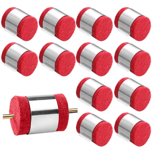
Steady Material: crafted from felt and metal, our welding wire cleaner pads promise steadiness; Specifically designed for rigorous environments like welding workshops, these pads withstand heavy usage and maintain their shape and efficiency over time; This product cleans wires and reduces scorching by 50%, ensuring smooth feeding of poorly cast, spiral, rusted, or excessively long wire feed bushings

Package list: 30 pieces of 0.030 inch mig welder tips.
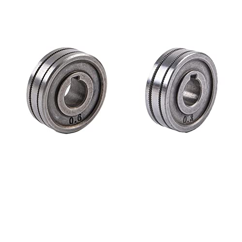
These rollers are used for feeding MIG wire on welding machines, fits directly onto the motor shaft.
Common Causes
- Drive rolls that do not match the wire diameter or type
- Too little or too much drive-roll pressure
- A liner that is dirty, damaged, too long, too short, or the wrong size
- A contact tip that is worn, undersized, oversized, overheated, or fused to the wire
- Excessive spool-brake tension
- A kinked gun cable
- Rusty or contaminated wire
- Improper trimming or installation of the liner
- Feeding soft aluminum wire through an unsuitable system
Safe Wire-Feed Troubleshooting
- Turn off and isolate the welder before opening the feeder or touching the wire path.
- Release drive-roll pressure and remove the damaged section of wire.
- Inspect the spool for tangles, rust, side drag, or loose wraps.
- Confirm the roll groove and diameter marking.
- Inspect the inlet guide, liner, diffuser, and contact tip.
- Route the gun cable as straight as practical.
- Rethread the wire according to the manual.
- Apply only enough drive-roll pressure for reliable feeding.
- Use the manufacturer’s insulated-block test while keeping hands away from the moving wire.
- Make a test weld and confirm that feeding remains stable under arc load.
During a rushed shop job, I kept tightening the rolls because the wire slipped. The real restriction was farther downstream in the liner. Excess pressure crushed and shaved the wire until it birdnested. Cleaning or replacing the liner and returning the pressure to the minimum reliable setting solved it.
Choose the Correct Drive Roll
| Drive-Roll Type | Common Use | Important Note |
|---|---|---|
| V-groove | Many solid steel and stainless wires | Use the groove size marked for the wire diameter |
| Knurled groove | Many flux-cored wires | Excess pressure can still deform or shave the wire |
| U-groove | Soft aluminum wire | Often paired with an appropriate liner, spool gun, or push-pull system |
Burnback and Contact-Tip Problems
Burnback occurs when the arc travels up the wire and fuses it to the contact tip. Possible causes include interrupted feeding, excessive voltage for the wire speed, a blocked liner, too much spool drag, an incorrect tip, or poor start parameters.
Replace a damaged tip instead of drilling or forcing the wire through it. Confirm that the tip matches the wire and that the gun’s consumables are installed in the correct order.
Cracking Issues in MIG Welds
Cracks can form while the weld is hot, after it cools, or at the end crater. A crack is a serious discontinuity and should not be covered with another pass.
Why MIG Welds Crack
- A crater is left unfilled at the end of the weld
- The joint is highly restrained
- The base metal has high hardenability or an unsuitable composition
- Moisture, contamination, or hydrogen enters the weld
- The filler metal is incompatible with the base metal or service
- Preheat, interpass temperature, or heat input does not follow the procedure
- The joint design concentrates shrinkage stress
- The weld cools under conditions that create a hard, crack-sensitive heat-affected zone
On a high-carbon-steel practice job, preheat helped only after the material was identified and the procedure was checked. A universal 200–300°F recommendation would not have been responsible because the correct temperature depends on composition, thickness, restraint, hydrogen control, heat input, and service requirements.
How to Prevent Cracks
- Identify the base-metal grade before selecting filler or preheat.
- Use the specified WPS, filler classification, shielding gas, polarity, and heat input.
- Keep filler wire, joints, and consumables clean and dry.
- Use a crater-fill function or pause briefly to fill the termination without overheating it.
- Control tack size, sequence, restraint, and joint fit-up.
- Follow specified preheat, interpass, and postweld heat-treatment requirements.
- Remove the full crack and determine its cause before rewelding.
Crater cracks appeared at the ends of welds on a rebar practice assembly until I improved the termination. That does not mean any rebar can be welded. Reinforcing-bar welding may fall under AWS D1.4 and requires confirmation of bar weldability, filler, procedure, preheat, and project requirements.
Use the consumable classification and manufacturer’s data instead of relying on simplified labels:
| Wire Type | Useful Characteristics | Limitations and Checks |
|---|---|---|
| ER70S-6 | Higher manganese and silicon deoxidizer levels than ER70S-3; often tolerant of light mill scale or minor surface oxidation | It does not eliminate the need for cleaning, and it is not automatically the correct filler for every steel |
| ER70S-3 | Common choice for clean carbon steel where heavy deoxidizer content is not needed | Requires suitable surface preparation and is not defined simply as a universal “low-hydrogen” replacement |
| Flux-cored wire | Available in high-deposition, positional, gas-shielded, and self-shielded classifications | Gas, polarity, slag, mechanical properties, and diffusible-hydrogen designators vary by classification |
Improper Bead Profiles and Solutions
A bead that is excessively convex, concave, wide, narrow, irregular, or poorly tied in gives useful clues about the setup. It does not prove weld quality by itself, but it helps you decide what to inspect next.
I once made a furniture-frame bead that looked like a rope laid on the surface. The settings were too cold for the travel speed, and the toes had not blended into the base metal.
Convex or Rope-Like Bead
Possible causes include low voltage, low heat input, excessive travel speed, poor gun angle, or wire feed that is not balanced with the voltage. Check for poor toe fusion before increasing settings.
Concave or Washed-Out Bead
Possible causes include excessive voltage, wire feed that is too low for the arc length, travel speed that is too fast, an unsuitable vertical-down technique, or insufficient filler for the joint.
Irregular Bead Width
Possible causes include erratic feeding, inconsistent gun distance, a wandering travel angle, poor visibility, an unstable work connection, or contamination.
Do not use “higher voltage for convex and lower voltage for concave” as a complete rule. Voltage, wire feed, travel speed, transfer mode, joint position, and gun distance interact. Return to the recommended operating range and adjust in small steps.
Lack of Penetration Fixes
Lack of penetration leaves the joint root or required depth insufficiently fused. It may result from low heat input, poor joint preparation, excessive root face, tight fit-up, incorrect wire extension, an inaccessible root, or travel speed that does not suit the procedure.
A pipeline training mock-up once failed a bend test even though the face looked acceptable. Improving the bevel and root access helped, but the final setup still had to follow the qualified procedure.
How to Improve Penetration
- Prepare the bevel, root face, and root opening to the drawing or WPS.
- Use the specified wire, gas, polarity, and transfer mode.
- Keep the arc at the leading edge of the puddle.
- Maintain the recommended wire extension.
- Increase heat input only within the approved range.
- Adjust travel speed without letting the puddle outrun the arc.
- Use backing, back-gouging, or multiple passes only when the procedure permits.
Overlap and Distortion Control
Overlap occurs when weld metal rolls onto the base metal without fusing at the toe. It often comes from low heat, slow travel, excessive filler deposition, poor angle, or a puddle that has moved ahead of the arc.
Correct overlap by removing the unacceptable metal, restoring the recommended heat and travel balance, and keeping the arc where it can melt the base-metal edge.
Distortion is movement caused by uneven heating and shrinkage. Thin sheet, long continuous welds, poor fit-up, and heavily restrained assemblies are especially vulnerable.
Ways to Reduce Distortion
- Use the minimum weld size and length required by the design.
- Plan the sequence before welding.
- Use balanced, staggered, back-step, or skip sequences when the procedure permits.
- Clamp and fixture the work without creating excessive restraint.
- Use short welds and allow heat to spread between locations.
- Maintain consistent fit-up and tack spacing.
- Avoid overwelding.
Clamping a furniture frame helped hold it flat, but clamps alone did not solve distortion. The weld sequence and total heat input mattered just as much.
Slag Inclusions in Flux-Cored Welding
Flux-cored arc welding, or FCAW, can leave a slag layer over the bead. Slag inclusion occurs when some of that nonmetallic material becomes trapped in the weld. This is different from porosity, which consists of gas cavities.
Common Causes
- Failure to remove slag between passes
- Poor joint access
- Incorrect work angle
- Excessive weaving
- A convex bead or narrow groove that traps slag at the toes
- Incorrect travel direction for the wire
- Heat and travel settings that do not allow slag to rise behind the puddle
How to Prevent Slag Inclusions
- Follow the wire maker’s polarity, gas, and travel-direction instructions.
- Remove all slag and loose deposits between passes.
- Grind difficult toes or starts when the procedure permits.
- Use a joint angle that provides access to the root and sidewalls.
- Keep the arc on the leading edge while allowing slag to remain behind the puddle.
- Use stringers or a controlled weave suitable for the joint.
On a multi-pass beam practice joint, trapped slag appeared where the previous bead had a steep toe and had not been cleaned fully. Better interpass cleaning and bead placement fixed the inclusion problem. The porosity check remained a separate gas and contamination diagnosis.
Polarity, Gas, and Transfer-Mode Mistakes
A welder can produce an arc with the wrong polarity and still deposit metal, which makes polarity mistakes easy to overlook. The result may be heavy spatter, shallow fusion, unstable transfer, poor bead shape, or overheated consumables.
- Solid-wire GMAW: Commonly uses direct-current electrode positive, but verify the wire and machine.
- Self-shielded FCAW: Many wires use electrode negative, but classifications vary.
- Gas-shielded FCAW: Often uses electrode positive, but the wire data sheet controls.
The shielding gas also changes arc behavior, penetration profile, transfer mode, spatter, and bead shape. A 75% argon/25% carbon-dioxide blend is common for short-circuit welding on mild steel, but it is not correct for every wire or transfer mode. Pure carbon dioxide, argon-rich blends, tri-mixes, and pure argon all have specific applications.
Do not increase gas flow automatically when porosity appears. First check leaks, cylinder contents, nozzle condition, drafts, gun angle, wire extension, and contamination. Excessive flow can become turbulent and draw surrounding air into the shielding envelope.
Products Worth Considering

APPLICATION: The ARCCAPTAIN gas pressure regulator can be used with argon, helium, and carbon dioxide gas tanks.

APPLICATION: It can be used with argon, helium and CO2 gas tanks

Compatible with CGA-580 tanks: Easily attach this Gas Pressure Regulator/Flowmeter to your Argon, Helium, and CO2 tanks with its CGA-580 inlet connector
Special Troubleshooting for Aluminum and Stainless Steel
Aluminum MIG Problems
Aluminum wire is softer than steel wire and can buckle inside a long conventional feed path. It also has a tenacious oxide layer and conducts heat rapidly.
- Use the recommended spool gun, push-pull system, liner, U-groove rolls, and contact tip.
- Keep the gun cable straight and reduce unnecessary feed resistance.
- Clean the oxide using a dedicated stainless-steel brush reserved for aluminum.
- Prevent cross-contamination from carbon-steel tools.
- Use the specified aluminum filler and shielding gas. Pure argon is common for many aluminum GMAW applications.
- Control fit-up and heat because thin aluminum can distort or burn through quickly.
The Miller aluminum and steel defect guide explains how feeding, oxide, heat, and shielding influence aluminum weld quality.
Stainless-Steel MIG Problems
- Match the filler classification to the stainless grades and service requirements.
- Use the shielding gas recommended for the selected wire and transfer mode.
- Use clean tools that will not embed carbon-steel contamination.
- Control heat input and sequence to reduce distortion and excessive discoloration.
- Use pulse only when the machine, wire, gas, position, and procedure support it.
Pulse mode can improve heat and transfer control in suitable applications, but it does not compensate for incorrect filler, poor cleaning, bad fit-up, or inadequate shielding.
Coated, Painted, and Galvanized Metal
Identify and remove coatings using a safe procedure before welding. Coatings can contaminate the weld and create hazardous fumes. Some plated or painted materials require specialized ventilation, respiratory protection, exposure assessment, or complete avoidance.
Never weld a container that held fuel, solvents, gas, or another hazardous substance unless it has been made safe under an approved procedure.
How to Inspect and Repair a Bad MIG Weld
- Stop welding and let the area cool safely.
- Clean the bead. Remove spatter, soot, slag where applicable, and loose scale.
- Inspect under good light. Look for cracks, undercut, overlap, visible porosity, incomplete tie-in, crater defects, arc strikes, and excessive distortion.
- Compare the weld with the applicable criteria. Use the drawing, WPS, code, and inspector where required.
- Mark the full affected area. The visible opening may not show the complete defect.
- Remove the discontinuity. Grind, gouge, or machine it using a method permitted by the procedure.
- Reprepare and clean the joint.
- Correct the root cause before rewelding.
- Reweld with the approved parameters and sequence.
- Reinspect using the required method.
Warning: Do not make an unapproved repair on a structural connection, pressure-containing part, lifting attachment, vehicle safety component, rebar assembly, or other critical item. Grinding out and rewelding a defect can change dimensions, heat input, residual stress, and material properties.
Conclusion: Build a Repeatable Troubleshooting Routine
The major MIG welding problems, from porosity and spatter to wire-feed faults, cracking, overlap, and shallow penetration, become easier to solve when you use a repeatable order. Start with safety. Verify the process, polarity, gas, work lead, consumables, and wire path. Clean the joint, return to the recommended settings, and test one change at a time on matching scrap.
The most important lesson is to understand why the problem occurred instead of covering it with another bead. I improved my own consistency by keeping a settings notebook with the machine, wire, gas, material, joint, position, and result from each test. That record saves time, but it never overrides the current manual, WPS, drawing, or governing code.
For U.S. workplace safety, consult the rules that apply to the industry and location, including relevant OSHA welding standards. For structural-steel code work, confirm the specified edition, amendments, errata, and project requirements for AWS D1.1/D1.1M:2025 or the other code that actually governs the material and application.
Frequently Asked Questions
Why is my MIG welder sputtering?
Sputtering can come from erratic wire feeding, wrong polarity, a poor work connection, contamination, excess stickout, inadequate gas coverage, or a voltage-to-wire-speed mismatch. Check the wire path and electrical connections before changing settings. If the wire repeatedly drives into the plate, the voltage may be too low for the selected wire speed.
How do I reduce spatter in MIG welding?
Verify polarity, shielding gas, wire classification, work-lead contact, wire extension, and feed consistency. Clean the material and return to the machine’s recommended settings. Fine-tune voltage and wire speed together. Anti-spatter products may reduce cleanup, but they do not fix an unstable arc.
What causes holes in my MIG welds?
Small pinholes are usually porosity caused by poor shielding, gas leaks, drafts, contamination, a clogged nozzle, excessive wire extension, or the wrong gas. Larger openings through thin material are burn-through caused by excessive heat, poor fit-up, a large gap, or slow travel.
Why won’t my MIG wire feed properly?
Inspect the spool, brake tension, drive-roll groove, roll pressure, inlet guide, liner, contact tip, and gun-cable bends. Rusty wire, a blocked liner, excessive spool drag, an incorrect tip, or over-tight rolls can cause slipping, shaving, burnback, and birdnesting.
Is my MIG weld too weak?
A smooth surface does not guarantee strength. Lack of fusion, shallow penetration, porosity, cracks, undercut, overlap, or the wrong filler can weaken the joint. Check joint preparation and procedure requirements. Safety-critical welds need the specified inspection or test rather than a visual guess.
Can too much shielding gas cause porosity?
Yes. Excessive gas flow can become turbulent and draw surrounding air into the shielding envelope. Use the flow range specified by the machine, gun, nozzle, gas, and consumable manufacturer. Check leaks, drafts, nozzle blockage, and gun angle before increasing flow.
Should I push or pull a MIG weld?
A modest push angle is common with solid-wire GMAW because it improves visibility and gas coverage. Many flux-cored wires use a drag technique to keep slag behind the puddle. The correct direction depends on the process, wire, position, joint, and welding procedure.
Sources
- Miller: Troubleshooting Weld Defects — porosity, fusion, burn-through, spatter, and bead-profile causes.
- Miller: Setting the Correct MIG Parameters — wire-size selection, machine setup, and bead-based fine-tuning.
- Miller: Guidelines for Gas Metal Arc Welding — transfer modes and GMAW troubleshooting tables.
- OSHA 1910.252 — general-industry hot-work, fire, ventilation, and related welding requirements.
- NIOSH: Welding-Fume Prevention Guidance — ventilation, exposure controls, worksite cleanliness, and PPE considerations.
- American Welding Society D1 Committee — current structural-welding code listings, scopes, amendments, and related standards.