More than once, I’ve had the metal cleaned, the joint fitted, and the gun ready—only to pull the trigger and get no wire. A MIG or flux-core welder that stops feeding can waste time and consumables, but the fault is often somewhere along a simple path: the spool, drive rolls, gun liner, or contact tip.
The fastest fix is to identify exactly what the machine is doing. A feeder that stays completely silent has different likely causes than one whose drive rolls spin while the wire stays still. Work through the checks below in order, and stop before opening the machine’s electrical cabinet or bypassing any safety device.
Quick Answer
A welder usually stops feeding wire because the contact tip is burned back or clogged, the liner is dirty, kinked, or incorrectly trimmed, the drive roll or tension is wrong, the spool brake is too tight, or the gun trigger or feeder circuit has failed. Start by unplugging the machine and checking the complete path from spool to tip.
Key Takeaways
- First note whether the drive rolls move, slip, stop under load, or create a birdnest.
- A burned-back or wrong-size contact tip is one of the quickest faults to isolate.
- Use the correct drive-roll groove and only enough pressure to feed without slipping.
- Keep the gun cable as straight as practical and install the exact liner specified for the wire and gun.
- Polarity and shielding gas must match the exact filler-metal label—not a general assumption about “MIG” or “flux-core.”
- Leave feeder relays, motors, control boards, and internal electrical repairs to qualified personnel.
At a Glance
| Time Required | About 10–30 minutes for common setup and consumable checks; longer if the liner or gun must be replaced |
| Difficulty | Beginner for setup checks; intermediate for liner replacement; qualified service technician for internal faults |
| Tools Needed | Owner’s manual, safety glasses, side cutters, pliers, clean brush, and the correct tip, liner, or drive roll if replacement is needed |
| Cost | Often no cost when adjustment solves the problem; otherwise the cost of the correct consumable or professional service |
Warning: Switch the welder off and disconnect input power before touching the drive system, removing the gun, cutting a birdnest, or replacing the liner. When power is restored for a brief feed test, wear eye protection, point the gun away from people, keep your hands clear of the rolls and wire, and follow the owner’s manual. Do not remove electrical covers, defeat interlocks, or probe an energized machine.
Diagnose the Wire-Feed Problem by Symptom
Before changing parts, watch and listen to what happens when you pull the trigger. Perform the initial inspection with the machine unplugged. Restore power only after reassembly and only for the controlled feed tests described in your owner’s manual.
| Symptom | Likely Causes | First Check |
|---|---|---|
| No click, gas, or drive-roll movement | No input power, open breaker, machine fault, thermal overload, disconnected gun trigger, damaged trigger switch, or control fault | Check the outlet, breaker, machine display, thermal indicator, and fully seated gun or trigger connector |
| The machine clicks, but the drive rolls do not turn | Feeder relay, drive motor, gearbox, control lead, or internal circuit fault | Stop after checking user-accessible plugs and fault indicators; arrange qualified service if the manual does not provide a user test |
| Drive rolls turn, but the wire does not move | Wire outside the groove, wrong roll size, too little roll pressure, excessive spool-brake tension, worn roll, or blocked wire path | Confirm spool movement, groove size, wire position, hub tension, and roll pressure |
| Wire immediately tangles behind the rolls | Blocked tip, clogged or kinked liner, excessive roll pressure, wrong liner size, short liner, or guide misalignment | Cut out the birdnest with power disconnected, then test the path with the contact tip removed |
| Wire feeds with the contact tip removed but stops with it installed | Burnback, spatter, oval wear, wrong tip, or a tip not intended for that wire or material | Install the exact replacement contact tip listed for the gun and wire |
| Wire feeds in the air but stops when the arc starts | Tip burnback, excessive drag, incorrect voltage or wire speed, poor work-lead contact, or an incorrect burnback setting on machines that provide one | Inspect the tip, then verify settings, work connection, polarity, and the filler-metal chart |
| The spool keeps unwinding after the trigger is released | Spool-hub brake tension is too loose | Adjust the hub only enough to stop overrun without making the drive rolls slip |
How Wire Feeding Works in a MIG or Flux-Core Welder
The feed system is a chain: spool → inlet guide → drive rolls → outlet guide → gun liner → contact tip. The feeder motor turns the rolls when the trigger or wire-jog control is activated. The rolls push the electrode through the gun until it exits the contact tip. A restriction or mismatch anywhere in that path can cause slipping, chatter, burnback, or birdnesting.
Two-Roll and Four-Roll Feeders
Many compact welders use a simple two-roll drive arrangement. Many intermediate and industrial feeders use four-roll systems, which provide more contact and can improve traction with larger wire or longer guns. Four rolls do not eliminate setup problems: the groove, pressure, spool brake, guides, liner, and contact tip still have to match the wire. Miller’s wire-feeder setup guidance also stresses correct drive-roll and hub tension.
Solid Wire, Self-Shielded Flux-Core, and Gas-Shielded Flux-Core
Solid steel wire such as ER70S-6 is commonly used with DCEP and shielding gas. For mild steel, C25—75% argon and 25% carbon dioxide—is a common short-circuit choice. A 90% argon/10% CO2 blend may be used for spray or pulsed transfer when the power source, wire, material thickness, and procedure support it. Miller’s mild-steel MIG setup guide recommends 0.023-inch wire for thinner material, 0.030 inch as a useful all-around size, and 0.035 inch for thicker work within the machine’s range.
Self-shielded flux-cored wire creates its own shielding and does not use an external gas cylinder. Common E71T-11 products normally use DCEN, but the spool label and filler-metal data sheet are the final authority. Miller’s flux-cored welding guide also calls for a knurled drive roll and careful roll and hub tension.
Gas-shielded flux-cored wire is a different process. Products classified as E71T-1C/M, for example, require the shielding gas and polarity listed by the manufacturer. The Hobart FabCO Excel-Arc 71 data sheet specifies 100% CO2 or 75–80% argon with the balance CO2, along with DCEP. Do not substitute the setup for an E71T-11 self-shielded wire.
Note: “Flux-core” does not automatically mean gasless or electrode-negative. Read the complete AWS classification and the manufacturer’s label each time you change wire.
Common Causes of a Welder Not Feeding Wire
Products Worth Considering

20Pcs Contact Tip .023'' Ø0.6mm

1. Package Includes 30 Premium Quality .023” (Ø0.6mm)welding Tips.

Premium quality Lincoln/Tweco style standard 11-30 (0.030") contact tips for 100L and Mini MIG guns
A Burned-Back, Worn, or Incorrect Contact Tip
Burnback occurs when the electrode melts into the contact tip and blocks the bore. Spatter, oval wear, or an incorrect tip can create the same restriction. Remove the nozzle with the power disconnected and inspect the tip. Replace it if the wire is fused inside, the bore is damaged, or the marking does not match the consumable chart for your gun and wire.
Do not drill a tip larger or assume that every aluminum setup should use a tip marked one size larger. Contact-tip bore, alloy, expansion allowance, and marking differ between consumable systems. Use the exact part number specified by the gun, wire, and equipment manufacturer.
A Dirty, Kinked, Worn, or Incorrectly Trimmed Liner
The liner supports the electrode through the gun cable. Tight bends increase friction and allow metallic debris to collect. A liner that is too small can bind; one that is too large can reduce wire support. A conventional liner trimmed too short leaves a gap, while one trimmed too long can buckle or compress.
Bernard and Tregaskiss list incorrect liner length, wrong liner size, debris, contact-tip burnback, feeder misalignment, and incorrect roll setup among the causes of non-feed and birdnesting in their MIG gun consumables troubleshooting guide.
Replace a kinked, flattened, heavily worn, or heat-discolored liner. When cleaning is allowed by the gun manufacturer, remove the welding wire first and use clean, dry compressed air as directed in the gun manual. Wear eye protection and point the outlet away from yourself and others. Trim and seat the replacement liner using the manufacturer’s gauge or exact procedure.
Wrong Drive Roll, Groove, or Pressure
The drive roll must match both the wire diameter and wire construction. Too little pressure allows slipping. Too much pressure can deform tubular or aluminum wire, create metal shavings, accelerate liner contamination, and make a blockage turn into a birdnest.
| Wire Type | Recommended Drive Roll | Why It Works | Watch For |
|---|---|---|---|
| Solid mild steel | V-groove | Grips hard wire without intentionally cutting into the surface | Slipping from low pressure or shavings from excessive pressure or the wrong roll |
| Flux-cored or metal-cored wire | Knurled roll specified by the machine or wire manufacturer | Provides traction on tubular wire | Crushing, flattening, or shaving from excess pressure |
| Aluminum | U-groove | Supports soft wire over a wider contact area | Birdnesting, galling, or deformation from the wrong groove or excess pressure |
| Stainless steel solid wire | Correct-size smooth V-groove unless the equipment manufacturer specifies otherwise | Provides controlled traction without knurling the wire | Cross-contamination, dirty guides, and mismatched liner material |
Pro Tip: Set only enough drive-roll pressure to feed consistently. Use the pressure-test method in your owner’s manual; do not solve every slip by tightening the knob another turn.
Spool, Hub-Brake, or Wire-Wrap Problems
Check that the spool is installed in the correct direction and that the wire enters the inlet guide in a smooth line. A crossed wrap, loose coil, bent leading end, damaged spool, or wire trapped under another wrap can stop feeding.
The hub brake should prevent the spool from coasting after the trigger is released. If it is too loose, the wire can unspool and tangle. If it is too tight, the drive rolls may slip while trying to pull wire from the spool. Adjust the hub according to the machine manual.
Do not feed visibly rusty, kinked, contaminated, or badly deformed wire through the gun. Store spools in a dry, enclosed location and protect them from condensation and grinding dust.
Gun, Adapter, and Wire-Guide Misalignment
A gun that is not fully seated can leave a gap between the feeder’s outlet guide and the liner. The wire may buckle in that gap instead of entering the gun. Inspect the gun connection, power pin, adapter, inlet guide, and outlet guide for looseness, wrong size, wear grooves, or misalignment.
Keep the gun cable as straight as practical during testing. Tight loops, sharp bends, a crushed cable, or a gun that is too long for the wire and feeder increase drag.
Trigger, Relay, Motor, or Control Faults
If the drive rolls do not move, verify input power, the machine’s process selection, any thermal-overload light, fault code, gun connection, and accessible trigger plug. Some machines disable feeding until they cool or until a process-specific gun is correctly connected.
A worn trigger switch, damaged control lead, failed feeder relay, motor fault, gearbox problem, or control-board failure can also stop the rolls. These faults may require electrical measurements inside the machine. Do not perform that work unless the manufacturer identifies it as a user procedure and you are qualified to do it.
Work-Lead Contact, Settings, and Burnback
The work clamp is part of the welding-current circuit; it is not the same thing as the machine’s protective equipment ground. Attach the work clamp firmly to clean metal and inspect the work lead for damage.
A poor work connection does not normally stop the feeder motor directly. It can destabilize the arc and contribute to the wire melting back into the contact tip, which then blocks feeding. Incorrect voltage, wire feed speed, stickout, polarity, or burnback settings can cause a similar tip blockage.
The OSHA arc-welding standard requires welding connections to be mechanically strong and electrically adequate and states that defective equipment must be removed from use until its safety is assured.
Step-by-Step Troubleshooting Procedure
Products Worth Considering
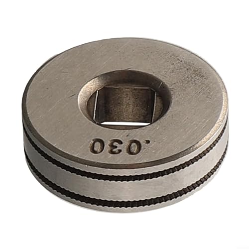
【Precision Design】The Mig Welder Wire Feed Drive Roller Roll Wheel is specifically designed for electric kits, ensuring precise and efficient wire feeding.

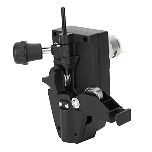
Steady & Efficient Wire Feeding: This wire feed motor delivers consistent and reliable wire feeding for MIG welding, compatible with both 0.8mm and 1.0mm welding wire. Its DC 24V 10W design ensures smooth operation, helping you maintain a clean and focused welding process without interruptions.
Step 1: Record the Exact Symptom
Note whether the machine clicks, releases gas, turns the drive rolls, moves the spool, slips at the rolls, birdnests, or stops only after the arc starts. Check the display for a fault or thermal warning. This observation determines which branch to follow.
Step 2: Disconnect Power and Inspect the Spool Area
Switch the machine off, unplug it or open the approved disconnect, and wait as directed in the manual. Inspect the spool, hub hardware, wire path, drive-roll groove, inlet guide, outlet guide, and gun seating. Cut out any birdnest without pulling tangled wire deeper into the gun.
Step 3: Remove and Inspect the Contact Tip
Remove the nozzle and contact tip. Look for fused wire, spatter, an oval bore, cracking, discoloration, or an incorrect size marking. Cut the wire end square and discard any section that was flattened or deeply marked by the drive roll.
Step 4: Test the Feed Path Without the Contact Tip
Reassemble the gun without the contact tip if your owner’s manual permits this diagnostic test. Restore power, wear safety glasses, keep your hands clear, point the gun into a safe area, and use the wire-jog control or trigger briefly.
- If wire feeds smoothly without the tip, replace the tip with the correct part.
- If the rolls slip or the wire birdnests, stop immediately and disconnect power again. The restriction is likely in the liner, gun connection, guides, or cable.
- If the rolls do not move, continue to the trigger and feeder checks instead of tightening the rolls.
Step 5: Correct the Roll and Spool-Hub Setup
Confirm that the correct groove is aligned with the wire and that the pressure arm closes squarely. Set the spool brake only tight enough to prevent overrun. Then follow the machine manufacturer’s drive-pressure test. The goal is steady feeding without crushing the wire or allowing the rolls to grind against a blockage.
Step 6: Clean or Replace the Liner
If the cable is kinked, the liner is incorrectly sized, or wire will not pass through with the tip removed, disconnect power and remove the wire and gun according to the manual. Clean the liner only if the gun manufacturer permits it. Replace it when it is worn, kinked, heat damaged, heavily contaminated, or incorrectly trimmed.
Lay the gun cable straight during liner installation. Seat both ends fully and use the supplied trim gauge or specified measurement. Guessing at the trim length can leave a feed-disrupting gap.
Step 7: Reload the Wire and Verify the Process Setup
Cut the wire end cleanly, prevent the spool from unwinding, and guide the wire through the inlet guide and correct roll groove without forcing it. Reinstall the correct tip after the wire exits the gun.
Then verify:
- the exact wire diameter selected on the machine;
- the correct drive roll and liner;
- the polarity shown on the spool label;
- the shielding gas required by that wire;
- the voltage and wire-feed starting point on the machine chart;
- a clean, secure work-clamp connection; and
- the recommended stickout or contact-tip-to-work distance.
Step 8: Stop and Arrange Service When Needed
Qualified service is appropriate when the drive rolls do not turn after accessible connections and fault indicators have been checked, the motor surges with no wire installed, the gearbox grinds, a fuse repeatedly opens, the machine smells burned, the control board reports a feeder fault, or damaged internal wiring is visible.
Do not keep pulling the trigger against a blockage. The rolls can shave or flatten the wire, overload the drive system, and build a larger birdnest.
Preventive Maintenance for Reliable Wire Feeding
- Keep the wire compartment closed when grinding or creating dust nearby.
- Store welding wire dry and remove a spool from the machine during long periods of humid storage.
- Inspect the tip, nozzle, diffuser, guides, and drive rolls before a large job.
- Remove metal shavings and dust using the cleaning method approved by the equipment manufacturer.
- Keep the gun cable straight or in broad, relaxed curves rather than tight coils.
- Replace a liner rather than repeatedly increasing drive-roll pressure to overcome drag.
- Check spool-hub tension whenever changing spool size or installing new hub hardware.
- Keep consumables organized by gun system and wire size to prevent mismatched tips and liners.
Smooth feeding comes from removing drag, not overpowering it with more drive-roll pressure.
Special Setup Tips for Flux-Core, Aluminum, and Stainless Wire
Self-Shielded Flux-Core
Use the polarity printed on the filler-metal label; common E71T-11 products normally use DCEN. Use the specified knurled drive roll without crushing the tubular wire. For welding technique, a drag or pull motion is standard. Miller recommends about 3/4-inch stickout for general flux-cored work and a normal travel angle of about 5–15 degrees.
Gas-Shielded Flux-Core
Do not treat gas-shielded FCAW as gasless wire. Verify the complete classification, shielding gas, polarity, flow range, wire diameter, and contact-tip-to-work distance on the product data sheet. Many E71T-1C/M products use DCEP, but the exact data sheet controls.
Aluminum
Aluminum wire has low column strength and buckles more easily than steel. Use the equipment manufacturer’s U-groove roll, compatible liner, aluminum contact tip, and recommended gun. A spool gun or push-pull gun shortens or controls the feed path and is often more reliable than pushing soft aluminum through a long conventional gun. MIG aluminum commonly uses 100% argon, but the filler and machine instructions remain the final authority.
Stainless Steel
Use dedicated, clean consumables when cross-contamination matters. Match the liner, roll, contact tip, filler wire, shielding gas, and machine program. Traditional short-circuit stainless setups may use helium tri-mix, while some newer machines are designed for approved argon-rich blends such as 98% argon/2% CO2. Do not select gas by habit alone.
When the Welder or Gun Needs More Than an Adjustment
A replacement gun may be justified when the cable is internally crushed, the power cable has failed, the trigger lead is damaged, the liner repeatedly overheats, or wire feeds only when the cable is held in one exact position. A spool gun or push-pull system may also be a practical upgrade for frequent aluminum work.
A feeder or machine upgrade may help when the existing unit cannot support the required wire diameter, gun length, duty cycle, or material. However, a more powerful feeder will not correct a mismatched tip, blocked liner, excessive hub tension, or poor installation.
Warning: Restoring wire movement does not prove that welds made during the fault are sound. Inspect and, when necessary, remove and remake suspect welds. Structural, vehicle-safety, lifting, pressure-containing, and code-regulated work should be evaluated under the applicable procedure by a qualified person.
Conclusion
Wire feeding depends on a clean, correctly aligned path from the spool to the contact tip. Start with the symptom, disconnect power, and check the easy restrictions first: a burned-back tip, wrong roll, bad tension setting, spool-hub drag, kinked liner, or loose gun connection.
If the rolls never move after the user-accessible connections and fault indicators are checked, stop before opening the electrical cabinet. A qualified technician can test the trigger circuit, feeder relay, motor, gearbox, and control board safely. Once the mechanical path and process setup are correct, the wire should feed smoothly without being crushed, shaved, or forced.
Frequently Asked Questions
Why won’t my flux-core wire feed even after cleaning?
Check whether the tubular wire has been flattened or shaved by excess roll pressure. Confirm that the knurled roll, groove size, liner, tip, and polarity match the exact wire. Also inspect the spool for rust, crossed wraps, and excessive hub tension. If the rolls do not turn at all, the fault may be in the trigger or feeder circuit rather than the wire path.
How do I know if my MIG liner is too long or the wrong size?
A liner that is too small can bind the wire. An oversized liner can provide poor support. A liner trimmed too short can leave a gap at a junction, while one trimmed too long may compress or buckle. Common signs include chatter, birdnesting, repeated burnback, metal shavings, and feeding that improves only when the cable is perfectly straight.
What causes birdnesting at the drive rolls?
Birdnesting occurs when the feeder keeps pushing but the path ahead is blocked or poorly supported. Common causes include contact-tip burnback, a clogged or kinked liner, incorrect liner length, excessive drive pressure, the wrong roll, guide misalignment, or a gap between the feeder and gun liner.
Can a bad work clamp cause wire-feed problems?
A poor work connection usually does not stop the feeder motor directly. It can make the arc unstable and cause the electrode to burn back into the contact tip. Once the tip is blocked, the rolls may slip or create a birdnest. Attach the work clamp firmly to clean metal and inspect the work lead for damage.
Should I add lubricant to MIG wire to improve feeding?
Do not apply oil, penetrating spray, or an unapproved lubricant. Contamination can collect dust, clog the liner, create fumes, and contribute to weld defects. Use clean, dry wire and only a cleaner, pad, or lubricant specifically approved by the wire, feeder, and gun manufacturer.
Why do the drive rolls turn while the welding wire stays still?
The wire may be outside the active groove, the groove may be too large, roll pressure may be too low, the roll may be worn, or the spool brake may be too tight. A blocked tip or liner can also make the rolls slip. Disconnect power before correcting the wire path or changing the roll.
Why does the wire feed normally until I strike an arc?
This pattern often points to contact-tip burnback, excessive liner drag, incorrect voltage or wire speed, excessive stickout, the wrong polarity, a poor work connection, or an incorrect burnback setting. Inspect the tip first, then verify the settings against the machine chart and filler-metal data sheet.
Sources
- OSHA — 29 CFR 1910.254, Arc Welding and Cutting — equipment connections, shutdown provisions, maintenance, and qualified repair requirements
- MillerWelds — Wire Feeders From Basic to Advanced — drive-roll pressure, spool-brake tension, feeder types, and maintenance
- Bernard and Tregaskiss — Welding Gun Consumables — non-feed, burnback, liner, contact-tip, guide, trigger, and birdnesting causes
- MillerWelds — MIG Welding for Mild Steel — solid-wire polarity, wire diameter, gas, work-clamp, and setup guidance
- MillerWelds — Flux-Cored Welding Basics — self-shielded setup, drive rolls, wire tension, stickout, and gun technique
- Hobart Filler Metals — FabCO Excel-Arc 71 Data Sheet — E71T-1C/M gas-shielded wire, shielding gases, and DCEP example