If you’re firing up an oxy-acetylene torch, the flame you choose can change the chemistry, heat concentration, appearance, and strength of the finished joint. Understanding the types of gas welding flames and their applications helps you avoid oxidation, carbon pickup, overheating, poor filler flow, and weak welds.
The three main oxy-acetylene settings are neutral, carburizing or reducing, and oxidizing. Neutral is the normal starting point for most welding. A slightly reducing flame is useful for selected brazing, hardfacing, and alloy-specific procedures. An oxidizing flame has limited joining applications and should not be confused with the separate oxygen jet that performs oxy-fuel cutting.
Quick Answer
Use a neutral oxy-acetylene flame for most gas welding. Use a slightly carburizing or reducing flame only when the filler, flux, alloy, or procedure calls for it. Reserve an oxidizing flame for limited copper-alloy and specialty work. For cutting steel, use a proper cutting tip, neutral preheat flames, and the separate cutting-oxygen jet.
Key Takeaways
- A neutral flame has a sharply defined inner cone and is the standard choice for most oxy-acetylene welds.
- A carburizing flame contains excess acetylene and shows an acetylene feather; a heavily sooting flame is too rich.
- An oxidizing flame contains excess oxygen, has a short sharp cone, and can damage ordinary steel welds.
- Regulator pressures must come from the exact torch-tip chart. Do not use one pressure recipe for every torch.
- Heat input is controlled mainly with the correct tip, travel speed, working distance, and technique—not by using the wrong flame chemistry.
- Oxy-fuel cutting depends on a high-pressure oxygen stream after preheating; it is not simply welding with an oxidizing flame.
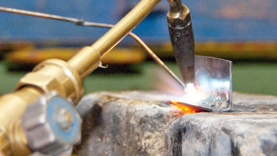
Image by mechanicalgiants
At a Glance
| Time Required | About 10–15 minutes for inspection, leak testing, purging, lighting, and a scrap-metal test |
| Difficulty | Intermediate; supervised training is strongly recommended before independent use |
| Tools Needed | Approved oxy-acetylene outfit, correct tip, manufacturer tip chart, friction striker, leak-test solution, tip cleaners, PPE, fire extinguisher, and scrap metal |
| Cost | Low per practice session once the equipment is owned; actual gas use depends on tip size, flow rate, and operating time |
Warning: Oxy-fuel equipment combines high-pressure oxygen, flammable fuel gas, open flame, hot metal, and potentially toxic fumes. Get hands-on training, read the exact equipment manual, secure cylinders valve end up, keep oxygen equipment free of oil and grease, provide ventilation, and never use acetylene above 15 psig. Never use a flame to check for leaks.
Why Gas Welding Flames Matter
Gas welding is not only about reaching a high temperature. The oxygen-to-fuel ratio changes how the flame reacts with the molten base metal and filler. The wrong setting may oxidize alloying elements, add unwanted carbon, make a brazing flux fail early, create excessive soot, or overheat the edges of a thin joint.
Flame selection also affects puddle behavior. A correct neutral flame on clean mild steel usually produces a calm, controllable puddle. An oxygen-rich flame may make steel spark, foam, or form excess oxide. A heavily acetylene-rich flame can deposit soot and may introduce carbon into materials that should not absorb it.
Choose the flame for the metal and joining procedure, then control heat with the correct tip size, working distance, travel speed, and torch movement.
What Is Gas Welding?
Gas welding, formally called oxyfuel gas welding when oxygen and a fuel gas are used, melts the joint edges with a flame. Acetylene is the usual fuel for fusion gas welding because it creates concentrated heat close to the tip. A compatible filler rod may be added to the molten pool, although some thin joints can be fused without filler when the procedure permits it.
Oxyfuel equipment can also be used for brazing, soldering, heating, straightening, hardfacing, and cutting. These are different operations. Brazing melts the filler without melting the base metal. Oxy-fuel cutting preheats suitable steel and then uses a separate stream of cutting oxygen to oxidize and remove the metal.
Note: The visual descriptions in this guide apply mainly to oxy-acetylene. Propane, propylene, natural gas, hydrogen, and air-fuel equipment have different flame shapes, heat distribution, tips, mixers, and lighting procedures. Use the manual written for the actual fuel and equipment.
How Gas Welding Works
The torch mixes oxygen and acetylene before the gases leave the tip. In an approximately neutral oxy-acetylene setting, the torch supplies roughly equal volumes of the two gases. Combustion continues in the surrounding air, which supplies additional oxygen to the outer flame envelope.
The visible flame has two main reference zones:
- Inner cone: The bright, sharply defined cone nearest the tip. Its shape helps the welder judge the oxygen-to-acetylene ratio.
- Outer envelope: The larger, softer flame surrounding and extending beyond the inner cone. Secondary combustion continues in this area.
The most useful concentrated heat is near and just beyond the inner-cone tip. Keep the cone off the molten pool unless the equipment or procedure specifically directs otherwise. A cone touching the work can disturb combustion, overheat the spot, and cause popping or contamination.
An oxy-acetylene flame is commonly described as reaching roughly 5,600–6,000°F under published test conditions. The exact value changes with gas ratio, flow, measurement point, and equipment. For practical welding, flame chemistry and heat placement matter more than chasing a single maximum-temperature number.
Safety First
Wear safety glasses with side protection plus approved gas-welding goggles, a face shield, or a suitable welding helmet. OSHA’s shade-selection guide lists shade 3–4 for torch brazing, 4–5 for light gas welding up to 1/8 inch, 5–6 for medium gas welding, and 6–8 for heavy gas welding. Select a lens that protects your eyes while still letting you see the puddle clearly.
Use flame-resistant clothing, leather gloves, closed footwear, and hearing protection when the work creates harmful noise. Keep a suitable fire extinguisher nearby and remove combustible material from the hot-work area. Remember that heat, sparks, and slag can pass through gaps and ignite material on the hidden side of a wall, floor, or partition.
- Secure oxygen and fuel cylinders so they cannot fall. Store and use acetylene cylinders with the valve end up.
- Keep oxygen valves, regulators, fittings, hoses, and gloves free of oil and grease.
- Inspect hoses, regulators, connections, check valves, flashback arrestors, torch valves, and tips before use.
- Use approved leak-test solution or oil-free soap and water. Never test with a flame.
- Light the torch only with a friction striker or another approved igniter.
- Do not use oxygen to blow dust from clothing, cool yourself, or ventilate a space.
- Do not take oxygen or fuel-gas cylinders into confined spaces.
- Never perform hot work on a used drum, tank, pipe, or container until it has been properly cleaned, isolated, and declared safe.
- Remove paint, plating, oil, and other coatings when required and use suitable ventilation or respiratory protection for the material involved.
Check valves help stop reverse gas flow. Flashback arrestors are designed to stop flame from traveling farther into the system. They perform different jobs, so one should not automatically be treated as a substitute for the other. Follow the torch manufacturer, employer safety program, and applicable rules for placement and inspection.
The Three Types of Gas Welding Flames
The flame type is identified mainly by the shape of the inner cone, the presence or absence of an acetylene feather, the sound, and the way the molten metal behaves. Always begin with the regulator settings required by the exact tip, then make the flame adjustment at the torch according to its manual.
| Flame type | Visual signs | Normal applications | Main risk |
|---|---|---|---|
| Neutral | Sharp inner cone, no acetylene feather, steady sound | Most steel welding, many cast-iron and stainless procedures, general heating, and many brazing jobs | Can still overheat thin metal if the tip is too large or travel is too slow |
| Carburizing or reducing | Visible feather extending beyond the inner cone; softer flame | Selected brazing, hardfacing, high-carbon or specialty procedures, and alloy-specific aluminum work | Excess soot or carbon pickup if set too rich |
| Oxidizing | Short, sharp inner cone; pale or intense appearance; noticeable hiss | Limited brass, bronze, copper-alloy, or specialty procedures | Oxidation, alloy loss, porosity, or poor mechanical properties on unsuitable metals |
Neutral Flame
A neutral flame is the standard choice for most oxy-acetylene welding. At the torch, it uses approximately equal oxygen and acetylene flow and does not intentionally add carbon to or strip alloying elements from the molten weld.
How to Set a Neutral Flame
Install the correct welding or brazing tip and set both regulators from the manufacturer’s chart while the gas is flowing as instructed. Purge each hose separately using the specified procedure. Never copy pressures from a different brand, tip family, or torch size.
Using the torch manufacturer’s lighting sequence, open the specified fuel valve only enough to ignite safely and light it with a friction striker. Adjust the fuel until heavy smoke and soot disappear without making the flame lift away from the tip. Slowly add oxygen. The acetylene feather will shorten until it disappears into a clean, sharply defined inner cone. That is the neutral reference point.
Pro Tip: Do not control heat by starving a large tip with nearly closed torch valves. Use the tip size recommended for the metal thickness and operation, then run it at the charted flow. A properly sized tip is usually steadier and less likely to pop or overheat.
When to Use a Neutral Flame
Use a neutral flame for most mild-steel gas welding and for many procedures involving low-alloy steel, cast iron, stainless steel, copper, and aluminum. The word “many” matters: filler, flux, alloy condition, joint design, and the approved procedure may call for a slight adjustment away from neutral.
For cast iron, flame selection is only one part of the job. Preheating, correct filler, controlled heat input, peening when specified, and slow cooling may be required to limit cracking. Stainless and aluminum also need clean, alloy-specific procedures and are often more easily joined with modern arc processes.
Practical Tips for Neutral Flames
Torch angle: A 40- to 50-degree work angle is a common starting range for some flat joints, but the correct angle changes with joint type, position, travel direction, material, and puddle behavior.
Working distance: Hold the tip so the concentrated heat near the inner-cone tip reaches the joint without burying the cone in the puddle. Use the distance stated in the tip or procedure instructions.
Filler rod: Select a rod compatible with the base metal and required strength. A general-purpose R45 or RG45 rod may suit some low-carbon-steel work, while R60 or another filler may be required by the drawing, service, or procedure.
Common mistake: Using a large tip and slowing the gas flow until the flame becomes unstable. Change tip size instead of operating outside the manufacturer’s recommended range.
Settings: There is no universal “5–7 psi” setting. Match the tip number and operation to the current manufacturer chart and verify pressure under the flow condition stated in the manual.
Pros and Cons of Neutral Flame
| Pros | Cons |
|---|---|
| Suitable for most oxy-acetylene welds | Still requires accurate tip and pressure selection |
| Does not intentionally oxidize or carburize the puddle | Too much heat can distort or burn thin material |
| Easy visual reference for other flame adjustments | Some alloys and fillers call for a slight reducing or oxidizing setting |
| Commonly suitable for brazing as well as welding | Does not correct dirty metal, poor fit-up, or the wrong filler |
Carburizing Flame
A carburizing flame, also called an acetylene-rich or reducing flame, contains more acetylene than the neutral setting. Its identifying feature is an acetylene feather that extends beyond the bright inner cone.
How to Set a Carburizing Flame
First establish a neutral flame. Then make the small torch-valve adjustment specified by the equipment or joining procedure until a controlled feather appears. The feather should be distinct enough to identify the reducing condition but not so large that the flame smokes, sheds soot, or becomes unstable.
Do not create a reducing flame by inventing regulator pressures such as high acetylene pressure and low oxygen pressure. The regulators must still supply the pressure and flow required by the installed tip.
When to Use a Carburizing Flame
A slightly reducing flame may be appropriate for selected brazing alloys, hardfacing operations, high-carbon-steel procedures, and materials that oxidize readily. Lincoln’s Harris brazing guidance recommends a neutral or slightly carburizing flame for most oxy-acetylene brazing while warning against an oxidizing flame.
Some aluminum welding or brazing procedures use a neutral to slightly reducing flame, but this is not a universal aluminum setting. Use a filler and flux approved for the exact base alloy and process. A 4043 filler may suit certain aluminum alloys, but it is not correct for every grade, heat-treatment condition, or service requirement.
Practical Tips for Carburizing Flames
- Joint preparation: Remove oil, oxide, paint, and contamination using methods suitable for the alloy. Use dedicated stainless-steel brushes on aluminum to prevent cross-contamination.
- Filler and flux: Match both products to the base metal. Aluminum welding flux, aluminum brazing flux, and copper-alloy brazing flux are not interchangeable.
- Watch the feather: A long feather, yellow smoke, or black deposit means the flame is too rich for most joining work.
- Watch the puddle: If steel becomes sluggish, dirty, or unusually hard after cooling, stop and verify the flame and filler rather than continuing the joint.
- Pressure: Keep the regulators at the tip-chart settings. Make the small chemistry adjustment at the torch as directed.
Pros and Cons of Carburizing Flame
| Pros | Cons |
|---|---|
| Provides a reducing atmosphere for selected procedures | Can deposit soot or add unwanted carbon if too rich |
| Useful for many brazing and hardfacing applications | Not a universal choice for aluminum, copper, or thin metal |
| Easy to identify by the acetylene feather | The feather can be misjudged in bright light |
| May protect oxidation-sensitive filler or flux when specified | Can produce unsuitable properties in ordinary steel welds |
Oxidizing Flame
An oxidizing flame contains more oxygen than a neutral flame. The inner cone becomes shorter and sharper, the outer envelope contracts, and the flame often makes a more noticeable hissing sound.
A slightly oxygen-rich flame can produce a high local temperature, but that does not make it better for ordinary welding. The excess oxygen may oxidize the puddle, remove useful alloying elements, increase porosity, and reduce weld quality.
How to Set an Oxidizing Flame
Start with a neutral flame. Add only the amount of oxygen required by the specific procedure. The inner cone will shorten and become more pointed. Stop if the flame becomes excessively noisy, the cone becomes unstable, or the molten metal sparks, foams, or forms heavy oxide.
Because its useful range is narrow, an oxidizing flame should not be selected simply because a job needs more heat. Choose a larger approved tip or a more suitable process when additional heat input is required.
When to Use an Oxidizing Flame
Oxidizing flames have limited applications in fusion welding or braze welding of certain brass, bronze, copper-alloy, and specialty materials. The exact amount of excess oxygen must come from the filler manufacturer, qualified procedure, or established shop instruction.
Do not use an oxidizing flame for ordinary mild-steel welding. It can oxidize the puddle and reduce the quality of the deposited metal. It is also not the correct description for oxy-fuel cutting: a cutting torch normally uses adjusted preheat flames plus a separate high-pressure oxygen jet.
Practical Tips for Oxidizing Flames
- Torch distance: Maintain the working distance required by the procedure. Pulling the torch away is not a reliable substitute for correct tip sizing.
- Filler: Use the alloy and flux stated by the approved procedure. A generic “brass rod” is not suitable for every brass or bronze base metal.
- Observe zinc-bearing alloys: Excess heat can increase zinc fuming and metal loss. Stop if the joint produces heavy white fumes and improve fume control before proceeding.
- Watch the puddle: Sparking, foaming, or a crusty surface on steel suggests an oxidizing condition or contamination.
- Pressure: Do not create the flame with a universal oxygen-pressure increase. Retain the tip-chart pressure and adjust the torch as instructed.
Pros and Cons of Oxidizing Flame
| Pros | Cons |
|---|---|
| Useful for a limited group of copper-alloy procedures | Damages weld quality on many steels and other alloys |
| Easy to recognize by its short cone and sharper sound | Can increase oxide, porosity, alloy loss, and fumes |
| Provides concentrated local heat | Not a substitute for correct tip size or cutting oxygen |
| May be required by a specific filler or procedure | Narrow operating range makes it unsuitable for beginners without supervision |
Step-by-Step Guide to Setting Your Flame
The sequence below is a general safety framework. Torch designs differ, so the manufacturer’s manual controls whenever its instructions differ from a general description.
- Confirm training and work authorization: Make sure you understand the torch, regulators, cylinders, check valves, flashback arrestors, fire-prevention plan, and emergency shutdown procedure.
- Inspect the area: Remove or shield combustibles, check both sides of the work, provide ventilation, and keep an extinguisher within reach.
- Inspect the equipment: Check cylinders, valve outlets, regulators, gauges, hoses, fittings, torch valves, tip seats, tip openings, and safety devices. Remove defective parts from service.
- Identify the exact tip: Confirm its manufacturer, family, size, fuel compatibility, operation, and material-thickness range.
- Set the charted pressures: Follow the tip chart and set pressure under the flowing condition described by the manufacturer. Never exceed 15 psig acetylene.
- Leak-test the system: Apply approved leak-test solution or oil-free soap and water to the required connections. Bubbles indicate leakage. Shut the system down and correct the problem before lighting.
- Purge each hose separately: Purge oxygen and fuel one at a time for the duration and valve opening stated in the manual. Never purge near an ignition source or into a confined space.
- Light with a striker: Follow the torch maker’s lighting sequence. Use a friction striker or approved igniter, never a cigarette lighter, match, hot metal, or another flame.
- Establish neutral: Adjust the fuel until heavy soot disappears, then add oxygen gradually until the acetylene feather just disappears and a clean inner cone remains.
- Adjust only when required: Move slightly toward reducing or oxidizing only when the base-metal, filler, flux, or qualified procedure calls for it.
- Test on matching scrap: Check puddle behavior, flame stability, working distance, travel speed, filler flow, and distortion before touching the finished part.
- Weld or braze: Maintain a stable torch angle and distance, heat both sides of the joint evenly, and add filler to the heated joint rather than melting it carelessly in the flame.
Warning: Popping, squealing, a flame burning inside the tip, a hot torch handle, smoke from the mixer, or a flame traveling into the hose can indicate backfire, sustained backfire, or flashback. Close the torch using the manufacturer’s emergency sequence, shut off the cylinders when safe, allow the equipment to cool, and inspect it before reuse.
Products Worth Considering

【 Innovative Swirl Combustion Tech – No Oxygen Tank Needed 】These torch tips (0386-0101 A-3, 0386-0102 A-5, 0386-0103 A-8) feature cutting-edge swirl combustion technology that boosts burn efficiency—so you get faster heating and higher working temperatures without hauling an oxygen tank. Complete fuel combustion means cleaner, more efficient brazing every time—saving you time on every job

READ THIS BEFORE YOU BUY:***These tips are compatible ONLY with Victor "J" Series Welding Handles - These Tips WILL NOT FIT Victor Series "100" or "300" Handles***
Safe Shutdown and Depressurization
Use the shutdown order specified for the torch. After extinguishing the flame, close both cylinder valves. Vent each line separately in a safe area, close the torch valves, and back out the regulator-adjusting screws until they turn freely. Confirm that both delivery-pressure gauges return to zero before storing the equipment.
Do not leave a pressurized torch unattended. Close the cylinder valves when work is finished and protect the cylinders, regulators, hose, and tip from impact, heat, contamination, and unauthorized use.
Choosing the Right Flame for Your Project
Start with the operation, then identify the base metal, filler, flux, joint design, thickness, service conditions, and governing procedure. Do not choose a flame from the base-metal name alone.
Scenario 1: Welding Mild Steel
For two properly prepared 1/8-inch mild-steel plates, a neutral flame is the normal choice. Select the tip from the torch chart, tack the joint to control movement, and use a compatible filler such as an R45 or R60 classification when it meets the job requirements.
Keep the inner cone just off the puddle, move at a pace that maintains fusion without enlarging the heat-affected zone, and add filler smoothly at the leading edge. If the edges melt away, change to a smaller tip or increase travel speed rather than making the flame heavily carburizing.
Scenario 2: Brazing Copper Pipes
For most oxy-acetylene brazing, use a neutral or slightly carburizing flame. Heat the tube and fitting evenly, allowing the base metal to melt the brazing filler. Do not point the inner cone at the rod until it melts independently of the joint.
For copper-to-copper joints, a suitable phosphorus-bearing brazing alloy may be self-fluxing. Copper-to-brass, copper-to-bronze, copper-to-steel, and other dissimilar combinations normally require the flux and filler specified by the manufacturer. Do not use phosphorus-bearing copper filler on ferrous metal unless the filler manufacturer expressly approves the application because brittle compounds can form.
For refrigeration or medical-gas tubing, follow the applicable code and procedure. A low-flow nitrogen purge may be required to limit internal oxide scale, and flux residue must not be left where it can contaminate the system.
Scenario 3: Cutting Thick Steel
Install a cutting attachment and the cutting tip specified for the steel thickness and fuel gas. Adjust the preheat flames as the manufacturer directs—commonly to neutral with acetylene—then heat the steel to its ignition temperature.
When the starting spot is ready, depress the cutting-oxygen lever. The concentrated oxygen jet oxidizes the hot steel, and the reaction helps sustain the cut while the jet removes oxide from the kerf. Maintain the correct tip height and travel speed so the cut stays square and slag is minimized.
Standard oxy-fuel cutting works best on carbon and low-alloy steels whose oxides behave properly in the cut. Aluminum, stainless steel, cast iron, and many nonferrous metals generally require another cutting process or a specialized technique.
Material and Operation Guide
| Material or operation | Typical starting flame | Important qualification |
|---|---|---|
| Mild-steel fusion welding | Neutral | Use compatible filler, tip size, joint preparation, and procedure |
| Low-alloy or high-carbon steel | Neutral or procedure-specified slightly reducing | Heat treatment and carbon control may be critical |
| Cast-iron welding or braze repair | Usually neutral; special steps may differ | Preheat, filler choice, and slow cooling control cracking risk |
| Stainless-steel gas welding | Usually neutral | Requires cleanliness, compatible filler, flux when specified, and strong fume control |
| Aluminum fusion welding or brazing | Neutral to slightly reducing when specified | Use alloy-specific filler and the correct aluminum flux |
| Copper-to-copper brazing | Neutral or slightly reducing | Some phosphorus-bearing fillers are self-fluxing on copper only |
| Copper to brass, bronze, or steel | Neutral or slightly reducing | Use the specified filler and flux for the metal combination |
| Brass or bronze fusion/braze welding | Neutral to slightly oxidizing when specified | Control heat and fumes; avoid excessive zinc loss |
| Hardfacing | Neutral or reducing, depending on alloy | Follow the hardfacing-alloy manufacturer’s procedure |
| General heating and bending | Usually neutral | Use an approved heating tip and adequate cylinder capacity |
| Oxy-fuel cutting of carbon steel | Manufacturer-specified preheat, commonly neutral | The cutting-oxygen jet performs the cut |
Factors to Consider
- Material: Confirm the exact alloy, coating, heat treatment, and service requirement rather than relying only on “steel,” “aluminum,” or “brass.”
- Operation: Welding, brazing, heating, and cutting use different tips, pressures, fillers, and techniques.
- Joint type: Butt, lap, edge, corner, and fillet joints need different angles, fit-up, tack placement, and filler control.
- Thickness: Select a tip that provides the needed heat. Thin metal does not automatically require a carburizing flame.
- Joint preparation: A 30-degree bevel per side may suit some procedures, but bevel angle, root face, and root opening must follow the drawing or WPS.
- Filler and flux: Verify that both products match the base metal and each other.
- Code requirements: Use the edition and welding procedure specified by the contract, employer, or authority having jurisdiction.
- Gas consumption: Cost depends mainly on tip flow, operating time, cylinder capacity, and technique—not simply whether the flame is neutral or oxidizing.
Practical Know-How for Welders
Joint Prep
- Cleanliness: Remove rust, oxide, moisture, grease, paint, plating, scale, and cutting residue using a method suitable for the metal.
- Dedicated tools: Keep stainless and aluminum brushes separate from carbon-steel tools to reduce cross-contamination.
- Fit-up: Maintain the root opening and alignment specified for the joint. A large unplanned gap increases filler use and heat input.
- Beveling: Prepare the groove angle, root face, and land from the drawing or procedure rather than using one bevel for every thickness.
- Tacking: Use enough tacks to hold alignment and control movement without creating oversized areas that are difficult to fuse.
- Coatings: Identify galvanized, cadmium-, lead-, chromium-, nickel-, or paint-coated materials before heating. Remove coatings where required and use the appropriate ventilation and respiratory controls.
Machine and Torch Settings
Oxyfuel equipment does not have amperage or voltage settings, so “machine settings” means choosing the correct torch, mixer, tip, gas, pressure, flow, safety devices, and working distance.
- Torch tip: Use the tip-chart range for the metal thickness and operation. Tip numbering is not standardized across every manufacturer.
- Regulator pressure: Set pressure while gas flows if the manual requires an at-flow reading.
- Cylinder capacity: Confirm that the acetylene cylinder can supply the tip’s withdrawal rate. A large heating tip may require a larger cylinder or manifold even when the regulator shows adequate pressure.
- Flame size: Do not turn a large tip down until it pops. Change to a smaller tip.
- Tip condition: Clean clogged openings with the correct-size tip cleaner. Do not enlarge, gouge, or reshape the holes.
- Hose condition: Replace cracked, burned, contaminated, or questionable hose rather than wrapping damaged sections with tape.
Common Mistakes and Fixes
| Problem | Likely cause | Safe response |
|---|---|---|
| Yellow, smoky flame | Too much acetylene, too little oxygen, or insufficient fuel velocity | Adjust according to the lighting procedure; verify tip pressure and cleanliness |
| Flame lifts away from the tip | Excess flow or wrong pressure for the tip | Shut down if unstable and check the tip chart |
| Inner cone is short and noisy | Oxidizing setting | Reduce oxygen toward neutral unless the procedure requires oxidation |
| Long acetylene feather or soot | Flame is too reducing | Add oxygen toward the specified setting or verify gas flow |
| Steel puddle sparks or foams | Oxidizing flame, contamination, or both | Stop, return to neutral, clean the joint, and test on scrap |
| Filler balls up instead of flowing | Base metal too cold, dirty joint, spent flux, wrong filler, or overheating | Reclean, re-flux when allowed, heat the joint evenly, and verify compatibility |
| Edges disappear or sheet warps | Tip too large, travel too slow, poor tack sequence, or excessive working temperature | Use a smaller tip, increase travel speed, and improve heat sequencing |
| Frequent popping | Tip touching work, overheated tip, low flow, damaged seat, or dirty orifice | Stop, cool and inspect the equipment, then correct the cause |
| Pressure falls during operation | Undersized cylinder, restricted hose, regulator problem, leak, or excessive tip demand | Shut down and inspect; do not compensate by exceeding rated pressure |
| Porosity | Dirty metal, wrong flame, damp flux, poor filler, turbulence, or trapped gas | Correct preparation and procedure before rewelding |
Backfire, Sustained Backfire and Flashback
A brief pop followed by the flame going out is commonly called a backfire. It may result from touching the tip to the work, overheating the tip, low gas flow, a blocked tip, a damaged seating surface, or incorrect pressures.
A sustained backfire occurs when combustion continues inside the tip or torch, often with a squeal or whistle. A flashback travels farther into the torch or hose and can damage equipment or create a serious fire and explosion hazard.
Do not relight repeatedly without finding the cause. Use the manufacturer’s emergency shutdown sequence, close the cylinder valves when safe, let the equipment cool, and inspect the tip, mixer, torch, safety devices, hoses, regulators, and pressures. Equipment exposed to a flashback may require testing or authorized service before reuse.
Industry Standards and Compliance
Safety practices for U.S. workplaces are addressed by OSHA 29 CFR 1910.253 for oxygen-fuel gas welding and cutting, OSHA 29 CFR 1910.252 for general welding requirements, and other standards that apply to the industry and work location. The American Welding Society also provides ANSI Z49.1:2021 and oxyfuel safety resources.
For aerospace fusion welding, AWS currently lists AWS D17.1/D17.1M:2024. For process piping, ASME lists ASME B31.3:2024. These standards should not be reduced to a blanket rule such as “ASME always requires a neutral flame.”
The governing contract, code edition, drawing, welding procedure specification, procedure qualification, filler specification, equipment manual, inspection plan, and local law determine what is permitted. Safety training alone does not qualify a welder to perform code work, and a technically sound flame does not make an unqualified procedure code-compliant.
Conclusion
Neutral, carburizing, and oxidizing flames are created by changing the oxygen-to-acetylene ratio at the torch, but the regulators must first be set for the exact tip and operation. A neutral flame is the all-purpose starting point for most gas welding. A slight reducing flame belongs in selected brazing, hardfacing, and alloy-specific procedures. An oxidizing flame has narrow specialty uses and can damage ordinary steel welds.
The safest approach is to match the tip, flame, filler, flux, and joint procedure to the actual metal. Inspect and leak-test the outfit, use the manufacturer’s pressure chart, test the flame on scrap, watch the puddle, and stop when the flame pops, burns back, becomes unstable, or produces unexpected fumes. Good flame control begins with safe equipment setup—not with memorizing one pressure setting for every job.
Frequently Asked Questions
What is the best flame for welding mild steel?
A neutral flame is the normal choice for mild-steel gas welding. It has a clearly defined inner cone without an acetylene feather and does not intentionally add carbon or excess oxygen to the puddle. Use a compatible filler and the tip, pressure, joint preparation, and technique required by the procedure.
Can I use a carburizing flame for all metals?
No. A reducing flame is useful for selected brazing, hardfacing, high-carbon-steel, and alloy-specific procedures. A heavily acetylene-rich flame can deposit soot or add unwanted carbon. Neutral remains the standard starting point for most oxy-acetylene welding.
Why does my gas weld have porosity?
Common causes include oil, rust, paint, moisture, oxide, incorrect flame chemistry, damp or unsuitable flux, contaminated filler, excessive turbulence, and poor puddle control. Stop and correct the cause before adding another pass. Increasing gas pressure without consulting the tip chart may make the problem worse.
Is an oxidizing flame good for welding?
Only for limited materials and procedures, such as selected brass, bronze, and copper-alloy work. Excess oxygen is harmful to many welds, especially ordinary steel, because it promotes oxide formation and alloy loss. Use an oxidizing flame only when a reliable procedure calls for it.
How do I know whether my flame is set correctly?
A neutral flame has a sharp inner cone and no acetylene feather. A reducing flame has a visible feather beyond the cone. An oxidizing flame has a short pointed cone and a sharper sound. Confirm the setting by testing on matching scrap and observing flame stability and puddle behavior.
What oxygen and acetylene pressure should I use?
Use the chart for the exact torch, mixer, fuel, tip family, tip size, and operation. Set pressure under the flowing condition stated by the manufacturer. There is no safe universal pressure for every number-one tip or every 1/8-inch joint, and acetylene must never be used above 15 psig.
Do I use an oxidizing flame to cut steel?
Not in the same sense as oxidizing-flame welding. A cutting tip uses preheat flames—commonly adjusted to neutral for acetylene—to bring suitable steel to ignition temperature. Pressing the cutting lever then releases a separate high-pressure oxygen jet that performs the oxidation and removes material from the kerf.
Can aluminum be gas welded with a carburizing flame?
Some aluminum procedures call for a neutral to slightly reducing flame, but a heavily carburizing flame is not a universal solution. Identify the alloy and use the filler, aluminum flux, tip, and flame recommended by the procedure or consumable manufacturer.
What should I do if the torch pops or flashes back?
Use the manufacturer’s emergency shutdown procedure and close the cylinder valves when it is safe. Let the torch cool, then inspect the tip, seat, mixer, valves, pressures, gas supply, check valves, flashback arrestors, regulators, and hoses. Do not keep relighting the torch until the cause is found and corrected.
Sources
- OSHA 29 CFR 1910.253: Oxygen-Fuel Gas Welding and Cutting — acetylene limits, cylinders, approved equipment, leak testing, and oxygen-system safety
- OSHA 29 CFR 1910.252: General Welding Requirements — eye protection, PPE, ventilation, confined spaces, coatings, and used-container hazards
- Miller: 10 Steps for Safe Oxy-Fuel Torch Setup — leak testing, purging, and manufacturer-specific tip pressures
- Lincoln Electric/Harris Brazing and Soldering Serviceman’s Guide — flame appearance, brazing-flame selection, flux, filler, and copper-tube procedures
- ESAB: What Is Oxy-Fuel Cutting? — preheating, cutting oxygen, suitable materials, and the oxidation process
- American Welding Society Free Safety Resources — ANSI Z49.1:2021, oxyfuel safety, cylinders, PPE, fumes, and ventilation