
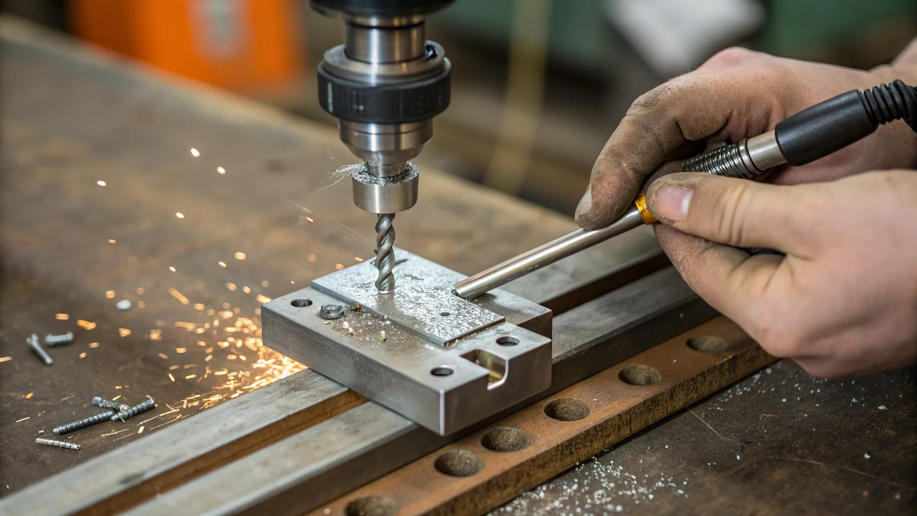
Metalworking Drill Jig: What It Does
A metalworking drill jig holds and locates a workpiece while also guiding the cutting tool. A welding fixture performs a related but different job: it holds and locates parts for welding without normally guiding the welding tool. Carr Lane’s workholding guidance makes this distinction clear, which is important when one shop setup is being used for both drilling and tack welding. See Carr Lane’s jig and fixture definitions.
Quick answer: Use the jig to locate and secure the workpiece, verify the drilling point or joint line, clamp the part so it cannot spin or shift, drill with a bit and speed appropriate for the material, then remove chips and re-check alignment before tack welding. Do not assume one drill speed or one clamping method works for every metal or hole size.
Last updated: August 8, 2026
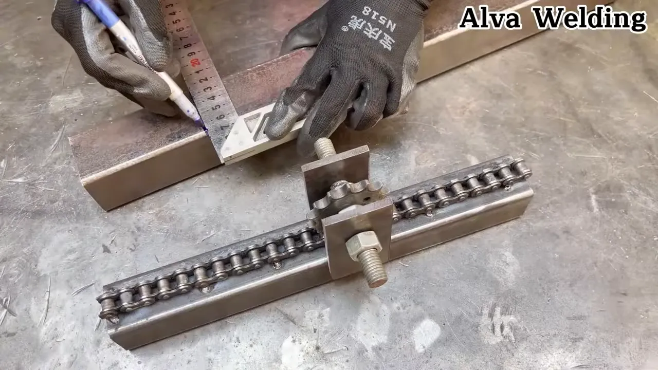
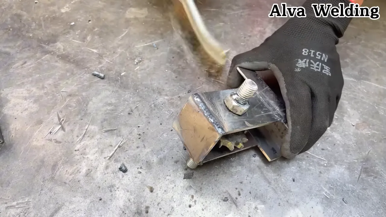
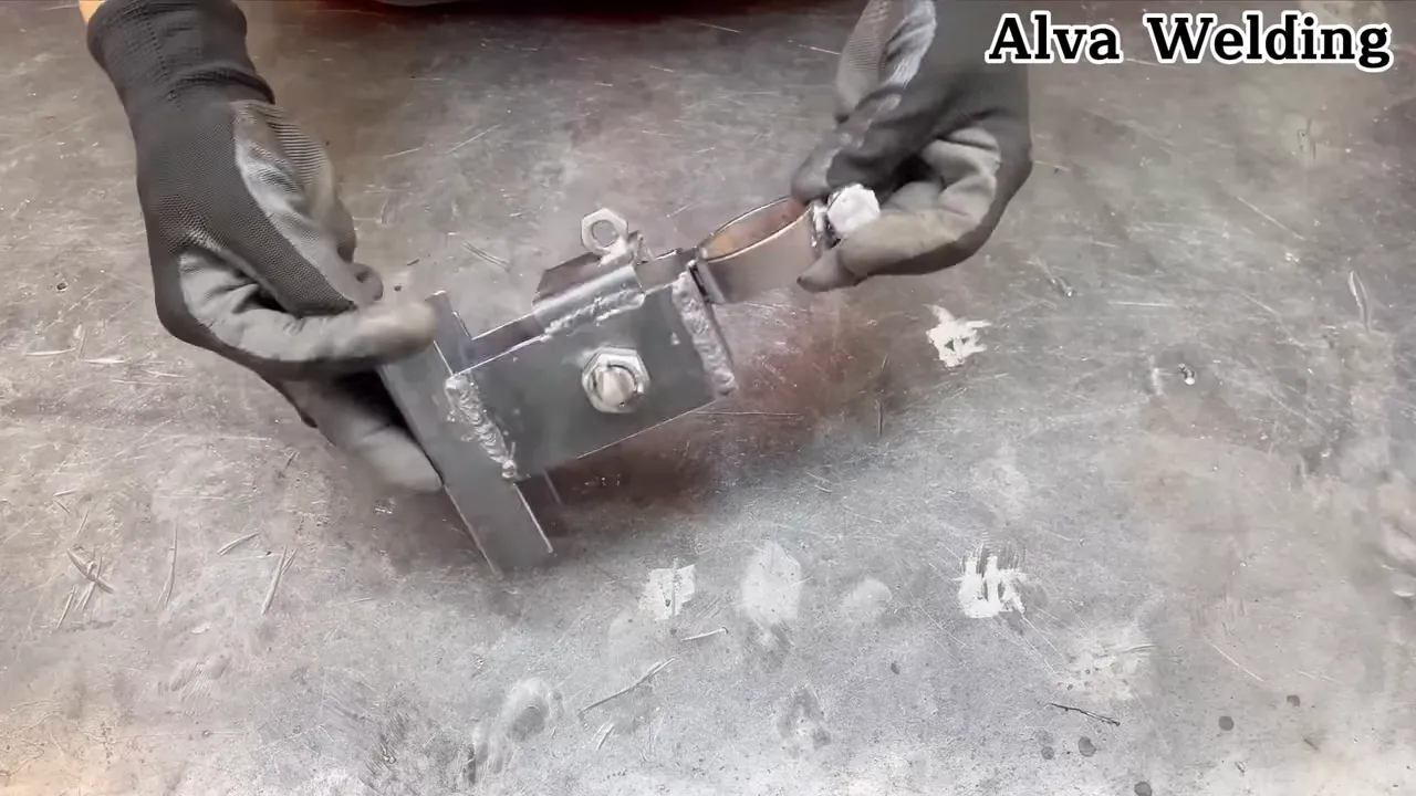
The setup pictured on this page appears intended to combine workholding, drilling alignment, and welding alignment. [VERIFY: confirm the pictured tool’s exact construction, drill-guide or bushing design, supported workpiece sizes, and intended materials before publishing specific compatibility claims.]
Products Worth Considering


INCLUDES: (12) Horizontal quick release toggle clamp (201B)
How Do You Set Up a Drill Jig for Metal?
A repeatable setup matters more than speed. The goal is to locate the part the same way every time, prevent movement, and keep drilling and welding as separate, controlled operations.
- Identify what the jig is controlling. For drilling, confirm which hole, bushing, guide, stop, or locating surface controls the drill position. For welding, identify the surfaces or stops that establish the joint position.
- Inspect and clean the locating surfaces. Remove chips, loose scale, dirt, and other debris that could prevent the workpiece from sitting firmly against the locator. Prepare the actual weld area according to the welding process and base material.
- Position the workpiece. Seat it fully against the jig’s stops or locating surfaces. Use a square, rule, layout line, or other suitable measuring tool to verify the position before tightening the clamps.
- Clamp the work securely. The workpiece must not rotate, lift, or slide when the drill engages. LSU’s drill-press safety guidance specifically calls for holding work in a vise or clamping it to the table instead of relying on hand pressure. Review LSU drill-press safety guidance.
- Choose the correct drill and speed. Match the bit type, diameter, speed, and cutting fluid to the workpiece material and tool manufacturer’s recommendations. There is no universal “low speed” rule for every thin-metal drilling job.
- Drill under control. Keep the drill aligned with the guide, avoid excessive feed pressure, and reduce pressure as the drill approaches breakthrough when appropriate for the tool and operation.
- Stop and clean before welding. Turn off the drilling equipment, remove chips with a suitable brush or tool, deburr the hole as needed, and clean away cutting fluid or debris that should not be exposed to the welding arc.
- Re-check the welding position. Drilling forces can alter a marginal setup. Confirm the joint location and clamp condition again before tack welding.
Products Worth Considering
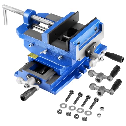
Non-Slip & Stable: Designed with anti-slip textured jaws, this cross slide vise delivers up to 7KN of clamping force to hold workpieces securely. It effectively resists slipping, ensuring steady work for drilling, engraving, grinding, and more

Made for T slot and T track setups: These hold down clamps are designed for compatible 8 mm, 10 mm, and 1/4 in T slot or T track systems used on drill presses, CNC routers, router tables, and fixture tables
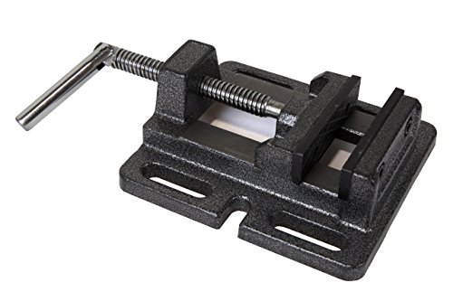
Grip woods, metals, plastics and more
What Should You Check Before Drilling?
Drilling accuracy depends on more than lining up a mark. A jig can improve repeatability, but it cannot compensate for a loose workpiece, the wrong drill, damaged tooling, or an unsuitable spindle speed.
| Check | Why It Matters |
|---|---|
| Workpiece restraint | The part must not spin or shift if the drill catches. |
| Guide alignment | The jig or bushing must be located over the intended hole position before drilling starts. |
| Bit condition | A damaged or dull bit can increase force, heat, and wandering. |
| Bit type | Twist drills, step drills, hole cutters, and other tools have different applications and operating requirements. |
| Drill speed | Correct RPM depends on the work material, drill diameter, and cutting tool. |
| Breakthrough support | Backing or proper support can improve control when drilling through thin material. |
For example, Milwaukee describes some of its step drill bits as optimized for high-speed cordless drilling in steel and plastic. That is one reason a blanket instruction to “always drill thin metal slowly” is too simplistic. Follow the requirements for the specific bit and material instead. See Milwaukee’s step-bit guidance.
Common Drill-Jig and Welding-Fixture Mistakes
Most problems come from setup errors rather than the jig itself. Check these points before blaming the fixture or drilling tool.
- Using the terms jig and fixture as if they are identical — a true drill jig guides the cutting tool, while a fixture primarily locates and holds the work.
- Inadequate clamping — a locator establishes position, but the workpiece still needs enough restraint to prevent rotation, lifting, or sliding under drilling forces.
- Over-clamping thin material — excessive force can bend a thin workpiece against the fixture and create an inaccurate hole or joint position.
- Using one drill speed for every job — select RPM according to the material, drill diameter, cutting tool, and equipment guidance.
- Skipping the second alignment check — verify the part again after drilling and before welding, especially if the setup was unclamped, deburred, cleaned, or repositioned.
- Allowing excessive welding heat to accumulate — fit-up, restraint, tack sequence, joint design, welding procedure, and total heat input can all affect distortion.
- Leaving heat-sensitive parts in the weld zone — drill bushings, plastic guides, magnets, coatings, or other components should not be exposed to welding heat unless their design specifically permits it.
TWI notes that welding distortion is influenced by factors including parent material, restraint, part fit-up, joint design, and welding procedure. Tack placement and welding sequence can also affect how a joint moves as it heats and cools. See TWI’s distortion guidance.
A Repeatable Drill-to-Weld Workflow
For a setup that performs both drilling and welding-alignment duties, treat the job as a sequence rather than one continuous operation:
- Locate the workpiece against the jig’s reference surfaces.
- Clamp it so drilling forces cannot rotate or lift it.
- Verify the hole position, joint line, angle, or squareness.
- Drill with the appropriate cutting tool and machine settings.
- Deburr and clean the drilled area and remove loose chips.
- Re-check the workpiece against the fixture locators.
- Tack the joint using the welding procedure appropriate for the material and joint.
- Inspect alignment before completing additional welding.
This sequence separates drilling accuracy from welding heat control. If the jig contains drill bushings, magnets, plastic parts, coatings, or other heat-sensitive components, remove or protect them as required before welding. [VERIFY: confirm whether the specific pictured jig is designed to remain attached during welding.]
Practical Tips for Cleaner, More Repeatable Work
- Use a center punch where appropriate for the drill and material to establish a clear starting location before drilling.
- Use the cutting fluid recommended for the material and cutting tool rather than assuming one lubricant is suitable for every metal.
- Keep locating faces, stops, and drill-guide surfaces free of chips. Even a small chip trapped under a workpiece can change its position.
- Remove metal chips with a brush or suitable tool rather than your fingers.
- When welding thin material, use sound fit-up and a tack or weld sequence that limits unnecessary heat concentration.
- Where the joint allows it, a suitable backing or chill bar can help support thin sheet during welding. See this guide on using backing with sheet-metal welding.
- For a deeper discussion of heat control and thin steel, see the site’s guide to welding thin metal with flux-core wire.
Safety Checks Before Drilling or Welding
Secure workholding is a safety requirement as well as an accuracy requirement. A metal workpiece that catches a drill can rotate violently if it is not clamped. Wear suitable eye protection, keep loose clothing and hair away from rotating equipment, use the correct tooling, and follow the drill or drill-press manufacturer’s operating instructions.
Welding introduces additional hazards including fumes, ultraviolet radiation, burns, electrical shock, and fire. OSHA recommends appropriate work practices, ventilation, eye and face protection, protective clothing, and other PPE based on the operation. Never weld an unknown or closed container, and identify coatings or contaminants before heating them. Review OSHA welding, cutting, and brazing hazards.
What is the difference between a drill jig and a welding fixture?
Both devices hold and locate workpieces. A drill jig also guides the cutting tool, commonly through a hole or drill bushing. A welding fixture primarily positions and holds parts so the joint stays in the required location while it is tacked or welded.
How do I keep a drill bit from wandering on metal?
Secure the workpiece, establish the hole location accurately, use a suitable center punch when appropriate, and use the correct drill or jig guide for the job. A true drill jig may use a guide hole or bushing to constrain the cutting tool and improve repeatability.
Should I always use low drill speed on thin metal?
No. Correct drill speed depends on the workpiece material, drill diameter, drill design, and manufacturer’s recommendations. Some step drills are designed for high-speed operation, while other cutters and larger diameters require different speeds. Use the guidance supplied for the specific cutting tool.
How do I reduce distortion when welding thin metal?
Start with good fit-up and appropriate restraint, then use a welding procedure and sequence that limits unnecessary heat input. Tack placement, short or distributed welds where appropriate, joint design, and welding sequence can all affect distortion. Re-check alignment as the work progresses instead of relying on the fixture alone.
Can the same jig be used for drilling and welding?
A combined setup can perform both functions if it was designed for them, but drilling and welding should still be treated as separate operations. After drilling, remove chips and unsuitable cutting fluid, re-check the workpiece location, and confirm that bushings, magnets, plastic components, coatings, or other fixture parts can safely tolerate the welding environment. [VERIFY: confirm the pictured jig’s welding rating and construction.]
Bottom Line
A good metalworking drill jig improves repeatability by locating the workpiece and guiding the drilling operation. A good welding fixture keeps parts located during fit-up and welding. When one setup is intended to do both jobs, accuracy comes from a disciplined sequence: locate, clamp, verify, drill, clean, re-check, tack, and inspect.
The remaining limitation of this page is the specific jig itself. Its construction material, guide or bushing dimensions, clamping range, tolerances, and welding-temperature limitations have not been established in the supplied source. Those details should be verified before making product-specific performance or compatibility claims.
