
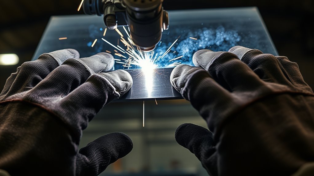
Thin sheet metal can burn through or distort when heat stays in one area for too long. A properly selected backing strip, removable backing bar, or chill bar supports the back of the joint and can help you control the weld pool. The right choice depends on the base metal, joint design, welding process, required root shape, and whether the backing must remain in the finished part.
This guide explains how to choose, fit, clamp, use, remove, and inspect backing for sheet metal welding. It also covers safety limits, process-specific techniques, common defects, and situations where a fitted patch or qualified welding procedure is the better option.
Quick Answer
Clean the joint and place a compatible backing bar tight against its back side. Clamp it so it cannot shift, test your settings on matching scrap, and weld with short stringer beads or spaced tacks. Remove temporary backing after cooling, then inspect both sides for fusion, cracks, porosity, undercut, contamination, and distortion.
Key Takeaways
- Use a copper or compatible aluminum chill bar for many light-gauge sheet-metal repairs, ceramic backing when the joint needs a formed root support, and permanent metal backing only when the design or welding procedure permits it.
- Keep temporary backing in close, even contact with the joint. A gap can let molten metal or slag run behind the work and create an irregular root.
- Backing helps support the root and manage heat, but it does not correct dirty metal, poor shielding, excessive arc length, or incorrect welder settings.
- Use short, straight welds with cooling pauses instead of a long weave or continuous bead on thin sheet.
- Do not improvise permanent backing on structural, pressure-retaining, lifting, suspension, roll-cage, or other safety-critical parts.
At a Glance
| Time Required | About 20 to 45 minutes for a small practice repair, excluding coating removal, backing fabrication, and final finishing |
| Difficulty | Intermediate; requires safe welding setup, accurate fit-up, and controlled heat input |
| Tools Needed | Compatible backing material, clamps, welder, cleaning tools, measuring tools, PPE, ventilation, and fire-control equipment |
| Cost | Low to moderate; reusable copper bars cost less over time, while shaped ceramic tape is a consumable |
What’s in This Article
- What Is a Backing Strip and Why Use It?
- Backing Strip, Backing Bar, and Backing Tape
- Before You Begin Using a Backing Strip
- What You’ll Need
- Choosing the Right Backing Material
- When Not to Use Improvised Backing
- Preparing the Sheet Metal
- Attaching the Backing
- Aligning the Backing
- Step-by-Step Instructions
- Welding Techniques by Process
- Common Mistakes
- Removing Temporary Backing
- Inspecting the Weld
- Troubleshooting
- Benefits for Different Thicknesses
- Frequently Asked Questions
- Conclusion
- Sources
What Is a Backing Strip and Why Use It?
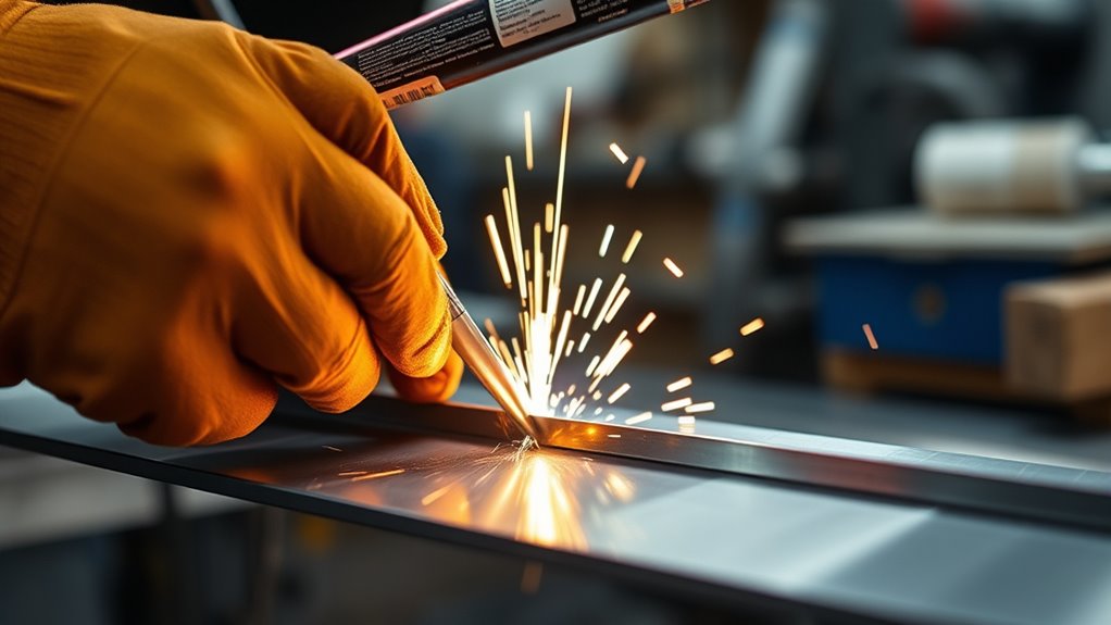
Weld backing supports the root side of a joint while the weld pool is molten. Depending on the job, the backing may be a permanent strip that becomes part of the joint or a temporary bar that you remove after welding.
A temporary copper or aluminum bar used against thin sheet metal is also called a chill bar. Its high thermal conductivity helps pull heat away from the weld zone. Miller recommends clamping a copper backing bar behind sheet metal as one method of reducing burn-through during MIG welding. Miller’s sheet-metal guidance also emphasizes tight fit-up, small beads, and adequate travel speed.
Ceramic backing performs a different job. It resists heat and may contain a groove that supports and shapes the molten root bead. It is common on joints where the welder works from one side and needs a controlled root contour.
Backing can support the molten root and help control heat, but weld quality still depends on clean metal, correct shielding, close fit-up, suitable filler, and proper welding technique.
Backing is especially useful on light-gauge panels, open seams, plug-weld holes, and small repairs where unsupported molten metal might fall through. It can improve root shape and reduce the amount of grinding needed, but it should not be used to hide a poorly fitted joint.
Note: This sheet-metal guidance does not transfer directly to specialty repairs such as welding cast iron with flux core. Cast iron has different cracking, filler-metal, and heat-control requirements.
Backing Strip, Backing Bar, and Backing Tape
The names sound similar, but they do not always describe the same product or joint detail.
- Permanent backing strip: A compatible metal strip that remains attached to the root of the finished joint. It must be permitted by the design or welding procedure.
- Temporary backing bar: A removable copper, ceramic, aluminum, stainless, or other approved backing placed behind the joint during welding.
- Chill bar: A temporary metal backing bar selected mainly to draw heat away from the sheet metal.
- Ceramic backing tape: Heat-resistant ceramic segments held by adhesive strips outside the active weld groove. It supports and shapes the root but does not function as a metal heat sink.
- Purge-retaining tape or foil-and-fiber tape: A temporary barrier used to contain backing gas. It is not automatically a replacement for purging.
- Backing gas: Shielding gas supplied to the back of a reactive or oxidation-sensitive weld. It is not a physical strip.
TWI’s guidance on weld design and backing describes permanent backing as a strip and removable backing as a bar. It also warns that a backing bar must contact the joint closely so molten metal or slag cannot run into a gap.
Before You Begin Using a Backing Strip
Identify the base metal, coating, thickness, joint type, gap, required weld length, and access behind the joint before choosing backing. You also need to know whether the weld is cosmetic, noncritical fabrication, or part of a safety-related structure.
Use the welder manufacturer’s setting chart or an approved welding procedure as your starting point. There is no universal voltage, amperage, wire-speed, or backing thickness that works for every gauge and alloy.
Warning: Do not improvise a permanent backing strip on structural, pressure-retaining, lifting, suspension, roll-cage, steering, chassis, or fatigue-loaded parts. Follow the engineering drawing, applicable code, and qualified welding procedure.
Prepare a Safe Welding Area
- Remove combustible materials and check the opposite side of walls, floors, panels, and cavities where sparks or conducted heat may start a hidden fire.
- Keep suitable fire-extinguishing equipment ready. Where workplace conditions require a fire watch, follow the applicable hot-work rules.
- Use local exhaust or another effective ventilation method that captures fumes without pulling away the shielding gas.
- Do not use oxygen as ventilation.
- Identify galvanized, painted, plated, lead-bearing, cadmium-bearing, stainless, and other coated or alloyed metals before heating them.
- Keep chlorinated cleaning solvents and their vapors away from the welding arc. Follow the cleaner manufacturer’s safety instructions and allow approved cleaners to evaporate fully.
- Do not weld inside a tank, vehicle cavity, container, or confined space unless the atmosphere, ventilation, rescue, and hot-work requirements have been evaluated by a competent person.
- Wear a welding helmet with a suitable lens, safety glasses, flame-resistant clothing, welding gloves, and hearing protection when needed.
OSHA’s general welding, cutting, and brazing requirements cover fire prevention, PPE, ventilation, coated metals, confined spaces, and cleaning compounds. NIOSH also warns that welding fume composition and exposure vary with the base metal, consumables, process, coatings, and work environment.
Warning: Grinding off a visible coating does not prove that the metal is safe to weld. Unknown coatings, vehicle undercoating, seam sealer, plating, and paint residue can produce hazardous fumes or ignite inside hidden cavities.
What You’ll Need
- Clean, compatible backing strip, bar, ceramic tape, or purge-support material
- Mechanical clamps, locking pliers, a backing spoon, or another heat-resistant holding method
- Welder, torch, electrode, wire, filler metal, and shielding gas suited to the base metal
- Grinder, scraper, stainless wire brush, abrasive pad, or file selected for the metal
- Measuring tape, square, marker, snips, saw, or another suitable cutting tool
- Matching scrap metal for a setup test
- Welding helmet, safety glasses, gloves, flame-resistant clothing, and suitable footwear
- Local fume extraction or effective ventilation
- Welding screens where other people may be exposed to the arc
- Fire-safe work area and suitable fire-extinguishing equipment
Use dedicated stainless-steel brushes and abrasives on stainless parts so carbon-steel residue does not contaminate the surface. Keep aluminum cleaning tools separate for the same reason.
Products Worth Considering

Package Include: You will receive 2 pieces of stainless steel strips, enough quantity to meet your various needs and craft making, and you can share them with your family and people around you. Please note that this product does not contain magnetism.

Premium Material – Made of high-quality nickel-plated steel, durable and corrosion-resistant.

Choosing the Right Backing Material for Your Project
Choose the backing according to its job. A chill bar must transfer heat and stay flat. Ceramic backing must resist heat and support the root shape. Permanent metal backing must be compatible with the joint and permitted to remain after welding.
| Backing Type | Common Use | Main Caution |
|---|---|---|
| Copper bar or spoon | Small holes, seams, plug-weld openings, and light-gauge steel repairs | Do not aim the arc directly at the copper; inspect critical alloy applications for contamination risk |
| Aluminum chill bar | Some sheet-metal work where a conductive, shaped backing fits the joint | Use only where compatible with the procedure; aluminum melts more easily than copper and can contaminate the weld if struck by the arc |
| Ceramic backing | One-sided joints requiring a supported or shaped root bead | It must match the groove and remain tightly seated; it is not a metal heat sink |
| Compatible permanent metal strip | Designed joints where the backing remains part of the weldment | Requires design approval, compatible material, close fit, proper tacking, and complete root fusion |
| Aluminum-foil or fiber purge tape | Containing backing gas on some stainless, nickel-alloy, or pipe joints | Follow the product and welding procedure; the tape does not automatically eliminate purge gas |
When using flux-cored welding, select a wire intended for the base metal, position, polarity, and shielding arrangement. The correct flux-cored wire type matters more than the backing material alone.
Products Worth Considering

Dual Safety Assurance Structure:Features stainless steel dual-bolt fastening, enhancing structural stability during high-temperature welding operations.

Bi-metal type, M42 grade, 93" long, 3/4" wide, 0.035" thick, 3TPI teeth profile

The CE certified A210 is a cow split leather rigger with patch palm and vein protection. Its cotton backing increases comfort and ventilation
Types of Backing Materials
Copper backing bars are common for thin sheet steel because copper conducts heat well and can be machined or shaped to fit a seam. A clean, substantial bar stays flatter and absorbs more heat than thin copper foil.
Ceramic backing tape uses heat-resistant ceramic segments, often with a formed groove. The adhesive normally sits beside the weld area rather than directly under the molten pool. Choose a product rated for the process, position, root opening, and expected heat.
Aluminum chill bars can also draw heat away, but they require more care because aluminum has a lower melting temperature than copper. Prevent direct arc contact and remove any transferred aluminum before making another pass.
Aluminum-foil and fiber tape may be used as a temporary purge dam or backing support in a procedure designed for that product. It should not be described as a universal substitute for backside shielding.
Permanent metallic backing strips become part of the joint. TWI states that permanent backing must be compatible with the base and filler metals, contact both joint edges closely, and be secured with suitable tack welds before the root pass.
Heat Resistance Considerations
Thermal conductivity and heat resistance affect the weld in different ways. Copper and aluminum pull heat away from the joint, while ceramic resists heat and supports the liquid weld metal without acting as a strong heat sink.
A large copper bar may reduce burn-through but can also make the joint feel colder. If you compensate with too much amperage, the sheet may overheat as soon as the bar loses contact or the weld reaches an unsupported area. Test the complete setup on matching scrap instead of adjusting by appearance alone.
Backing that is too thin may warp or lose contact. Backing that is dirty, damaged, or coated can transfer contamination. Replace cracked ceramic segments and clean reusable metal bars before each weld.
Application Method Selection
- Identify the backing’s purpose: Decide whether you need heat sinking, root support, root shaping, purge containment, or permanent joint backing.
- Match the base metal: Consider contamination, melting temperature, corrosion, and whether the backing remains in service.
- Match the joint: The backing should support the full root without blocking the torch, filler, or inspection area.
- Check removal access: Confirm that temporary backing can be released after the weld cools.
- Follow the procedure: Use the dimensions, groove shape, root opening, and tack sequence specified by the product manufacturer, drawing, or WPS.
Note: A temporary bar should release without becoming part of the root. If it repeatedly fuses to the weld, correct the fit-up, arc direction, heat input, or backing material before continuing.
When Not to Use an Improvised Backing Strip
A backing bar is not the right solution for every gap or hole. Stop and change the repair method when any of these conditions apply:
- The opening is large enough that you must build most of the repair from filler metal instead of joining sound sheet edges.
- The remaining metal is thinned by rust, cracking, heat damage, or previous grinding.
- The backing cannot sit flat against the root.
- You cannot remove a temporary backing bar or inspect the back of the repair when inspection is required.
- The part carries structural, pressure, lifting, steering, suspension, occupant-protection, or fatigue loads.
- The drawing or welding procedure prohibits permanent backing.
- The metal or coating cannot be identified.
- The process requires backside shielding that the proposed backing cannot provide.
For a large opening, cut back to sound metal and install a fitted patch. A patch with a controlled joint gap usually needs less filler and produces less distortion than trying to bridge a wide hole.
Getting Your Sheet Metal Ready for Backing Strips
Preparation determines whether the backing can contact the joint and whether the weld stays free from avoidable contamination. Clean both sides of the sheet because paint, rust, seam sealer, plating, oil, moisture, and grinding dust on the back can enter the molten root.
Measure the backing so it extends beyond the start and stop of the weld. The supporting face should cover the full opening without interfering with clamps, torch angle, or gas flow.
For structural joints, confirm that the joint preparation and permitted fillet-weld size match the design. Do not change the joint by adding permanent backing without approval.
Preparing the Work Surface
- Identify and remove coatings safely: Determine what the coating contains before grinding or heating it.
- Clean to sound metal: Remove rust, oxide, scale, oil, paint, adhesive, moisture, and embedded abrasive residue from both sides.
- Deburr the edges: Remove sharp burrs and plasma dross without thinning the sheet.
- Check the gap: Bring the edges into the gap required by the repair or procedure.
- Fit the backing: Shape the supporting face so it follows the panel and contacts the entire weld area.
Warning: Do not clean welding surfaces with chlorinated brake cleaner or another chlorinated solvent. OSHA requires chlorinated-hydrocarbon degreasing operations and vapors to be kept away from welding atmospheres because arc radiation and heat can produce highly toxic decomposition products.
Selecting the Right Backing
Use a clean copper bar or spoon for many small mild-steel sheet repairs. Use shaped ceramic backing when the procedure calls for a supported root profile. Select permanent backing only when it is part of the approved joint design.
Do not choose backing by thickness alone. Consider the alloy, process, joint position, root opening, required penetration, finish, and whether the backing may contact the arc.
Secure the backing with mechanical clamps where possible. Magnets can be useful for positioning, but strong magnetic fields may contribute to arc wandering in some DC welding setups. Move the magnet farther away or switch to a mechanical clamp if the arc becomes unstable.
Ensuring Proper Fitment
- Check full contact: Shine a light across the joint or use a thin feeler strip to find unsupported areas before welding.
- Control edge alignment: Keep the sheet faces level so one edge does not sit higher than the other.
- Verify the root opening: Do not rely on the backing bar to compensate for a changing gap.
- Secure the workpiece: Clamp the sheet independently so movement of the backing does not pull the joint out of position.
- Confirm removal: Make sure handles, clamps, or access points remain usable after the metal becomes hot.
A loose strip can shift, trap slag, create an irregular root, or let molten metal escape. A permanent strip with gaps along its edges can also leave unfused crevices.
Securely Attach Your Backing Strip
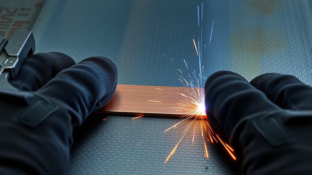
Place the backing against the root side of the joint and clamp it firmly enough to maintain contact without distorting the sheet. Use several clamps on a long bar so the center cannot bow away from the work.
For a small hole, a copper welding spoon or shaped copper block may be easier to hold than a long strip. For a curved panel, shape the backing to the curve instead of forcing the panel flat against a rigid bar.
Do not place ordinary combustible tape, plastic, wood, shop rags, or painted supports where sparks, hot metal, or conducted heat can reach them. Purpose-made ceramic backing tape should be installed according to its manufacturer’s temperature and positioning instructions.
Test-fit the torch and filler before starting. Confirm that the clamps do not block your travel path and that shielding gas can reach the joint.
Keep the sheet and backing clean by following sound flux-core preparation and setup practices when that process is used.
Align Your Backing Strip for Better Welding
Center the backing under the seam, groove, or hole. The support should extend past both ends of the planned weld so the start and crater do not fall over an unsupported edge.
- Keep the face flush: The backing should touch the root side evenly.
- Center grooves carefully: If ceramic backing has a root-forming groove, align the groove with the joint centerline.
- Recheck after tacking: Tack-weld shrinkage can open a gap between the work and backing.
- Watch curved panels: Use additional clamps or a shaped bar to prevent rocking.
- Stop if the backing moves: Do not continue filling an unsupported opening.
If the edges were plasma-cut, remove dross, oxide, and damaged material before fitting the backing. Gas selection during nitrogen plasma cutting may affect the cut surface, but the weld edge still requires inspection and preparation.
Step-by-Step: How to Use a Backing Strip
- Identify the metal and repair type. Confirm the alloy, thickness, coating, joint design, and whether the weld is safety-critical.
- Choose temporary or permanent backing. Use removable backing for ordinary sheet-metal heat control unless the design specifically requires a permanent strip.
- Prepare both sides. Remove contamination and coatings far enough from the heat-affected zone to prevent fumes, fire, and weld contamination.
- Shape the backing. Make the backing face follow the panel and cover the complete weld area.
- Fit and clamp the joint. Align the sheet edges, control the gap, and clamp the workpiece independently from the backing.
- Test on matching scrap. Reproduce the same metal, joint, gap, backing contact, welding position, and clamp arrangement.
- Set the welder. Start with the machine chart, consumable data, or WPS. Adjust only after examining the test coupon.
- Tack or stitch the joint. Use small, spaced welds and move around the joint to distribute heat.
- Complete the weld in short sections. Use straight stringer movement and the fastest travel speed that still produces fusion and a suitable bead.
- Allow controlled cooling. Let the joint cool naturally between sections. Do not quench a completed weld unless the procedure specifically allows it.
- Remove temporary backing. Release it after the joint has cooled enough to handle safely.
- Inspect both sides. Check the weld face, root, surrounding sheet, distortion, and any evidence that the backing fused or transferred material.
Pro Tip: Make the practice coupon slightly harder than the final joint by including the same gap, curve, access restriction, and backing contact. A flat scrap test may not reveal problems that occur on the real part.
Best Welding Techniques With a Backing Strip
Backing does not replace heat control. Keep the arc focused on the sheet edges and filler metal rather than the backing. Use the shortest practical arc, small welds, and a sequence that spreads heat across the panel.
Keep the work area clear of flammable materials that can ignite from grinder or welding sparks. Remember that heat can travel through the sheet and ignite material on its hidden side.
Proper Strip Placement
- Support the complete root: Extend the backing past the weld start and stop.
- Keep it clean: Remove previous weld spatter, oxide, adhesive residue, and transferred metal.
- Keep it stable: Add clamps where the bar can bow or rock.
- Avoid direct arc contact: Aim at the joint edges and puddle, not the backing material.
- Check gas access: Do not let clamps or backing interrupt shielding around the weld face.
Effective Heat Control
Use short welds or spaced tacks instead of laying one long bead across a thin panel. Move to a cooler area between welds and let the previous section lose its visible heat before returning.
Miller’s thin-sheet guidance recommends tight fit-up, fast travel, small stringer beads, and weld sequencing that avoids concentrating heat in one area. These controls work with the backing bar rather than depending on it alone.
A very large chill bar can pull enough heat away to make fusion difficult. Do not solve that problem by sharply increasing the settings without testing. Improve contact, use a more suitable bar, or adjust the qualified setup in small steps.
Pro Tip: Mark several short weld locations before you start. Following the marks helps you distribute heat instead of extending one section because the puddle happens to look good.
MIG Welding With a Backing Bar
- Use the machine chart and wire manufacturer’s range for the sheet thickness and shielding gas.
- Keep stickout and gun angle consistent.
- Use straight stringers or short trigger-controlled tacks rather than weaving.
- Travel fast enough to avoid an oversized puddle while maintaining fusion at both edges.
- Allow cooling time between sections and inspect the panel for movement.
- Use smaller wire where recommended for very thin material and compatible with the machine.
TIG Welding With a Backing Bar
- Use a small, correctly prepared tungsten and a stable low-current arc suitable for the material.
- Keep the arc short and add filler without dwelling over one point.
- Use a foot pedal, fingertip control, pulse function, or programmed slope when available and appropriate.
- Select filler close to the sheet thickness so you do not overheat the base metal while melting an oversized rod.
- Do not assume a copper backing bar replaces backside shielding on oxidation-sensitive alloys.
Flux-Cored Welding With Backing
Flux-cored wire often produces more heat and slag than a light-gauge solid-wire MIG setup. It may be unsuitable for extremely thin cosmetic panels. Where flux core is appropriate, follow the wire manufacturer’s polarity, thickness, and shielding instructions.
Ceramic backing can support some flux-cored root passes, but slag must not enter a gap between the ceramic and joint. Clean each pass as required before adding another weld.
Stainless Steel and Reactive Alloys
Stainless steel, nickel alloys, and titanium need extra attention to contamination and backside oxidation. TWI notes that copper backing may be chromium plated for some stainless and nickel-alloy applications to reduce contamination risk.
Do not assume any physical backing eliminates the need for backing gas. Follow the applicable procedure for oxygen limits, purge time, gas type, and purge duration. Titanium and high-integrity stainless work should be handled by a welder familiar with the required shielding controls.
Aluminum Sheet Metal
Remove the aluminum oxide with dedicated tools immediately before welding and keep the joint dry. Copper or aluminum chill bars may help manage heat, but they must fit closely and remain out of the direct arc.
Use filler metal compatible with the specific aluminum alloy. Do not select filler by appearance or by copying settings from steel.
Top Mistakes When Using Backing Strips
- Using the wrong type of backing: A chill bar, ceramic root former, purge dam, and permanent strip are not interchangeable.
- Skipping backside cleaning: Contamination trapped behind the panel can enter the root or produce hazardous fumes.
- Leaving a gap behind the joint: Molten metal or slag can run into the opening and form an irregular root.
- Aiming the arc at the backing: This can melt the bar, transfer material, or contaminate the weld.
- Increasing heat too aggressively: A large chill bar can make the joint seem cold, but excessive settings may burn through when contact changes.
- Trying to bridge a large hole: Install a fitted patch rather than building the repair almost entirely from filler.
- Using long continuous beads: Concentrated heat increases distortion and burn-through risk.
- Assuming backing prevents porosity: Check shielding gas, leaks, drafts, moisture, surface contamination, and arc length.
- Leaving temporary backing trapped: Plan access and removal before welding.
- Using permanent backing without approval: The strip changes the joint and may create corrosion, fatigue, inspection, or fusion concerns.
Wear suitable flame-resistant welding clothing and protect nearby people with screens or suitable eye protection.
Removing Temporary Backing and Finishing the Weld
Allow the joint and backing to cool before releasing the clamps. Metal bars can remain hot long after the weld loses its glow.
- Release the clamps carefully: Support the work so spring pressure does not move or bend the panel.
- Remove the backing straight away from the root: Do not twist a bar against a soft weld.
- Inspect for sticking: If the bar has fused locally, stop and determine whether the arc struck it or the backing material was unsuitable.
- Remove ceramic residue: Follow the product instructions and clean loose ceramic without hammering directly on thin sheet.
- Clean the root: Remove residue, spatter, oxide, and transferred backing material with tools suitable for the base metal.
- Finish gradually: Grind only the excess weld metal needed for the required contour. Avoid thinning the surrounding sheet.
Do not hide a crack, pore cluster, lack of fusion, or contaminated root under body filler, coating, or paint. Repair the weld first.
How to Inspect Your Weld Quality After Using a Backing Strip
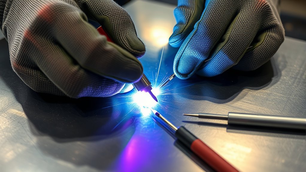
Inspect the weld after it cools and after temporary backing or loose residue has been removed. Use good lighting and examine both the face and root when access allows.
Check the Weld Face
- Consistent width and contour
- Fusion into both sheet edges
- No visible cracks or crater cracks
- No open pores or clusters of surface porosity
- No deep undercut along the toes
- No excessive overlap or cold-looking rolled edges
- No burn-through or oversized holes
- No excessive spatter or evidence of unstable shielding
Check the Root and Surrounding Sheet
- Continuous fusion where a complete joint is required
- No trapped backing material
- No irregular metal that ran into a gap behind the joint
- No severe oxidation, sugaring, or contamination on alloys that require backside shielding
- No cracks beside the weld
- No unacceptable distortion, thinning, or heat damage
A visually smooth bead is not proof that a weld meets structural requirements. Acceptance limits for undercut, porosity, penetration, profile, and other imperfections depend on the drawing, code, service, and welding procedure.
For practice work, cut and bend a separate test coupon made with the same setup. Do not destructively bend a finished component unless the inspection plan calls for it.
Set welding amperage, voltage, and wire speed from welding guidance rather than copying unrelated plasma-cutter tip and amperage settings. Plasma cutting and arc welding use different consumables and operating ranges.
Troubleshooting Backing Strip Issues in Welding
| Problem | Likely Causes | Correction |
|---|---|---|
| Burn-through | Excessive heat, slow travel, wide gap, thin edge, poor backing contact, or unsupported start and stop | Reduce heat input, improve fit-up, increase controlled travel speed, shorten welds, and support the full root |
| Lack of fusion | Backing removes too much heat, settings are too low, travel is too fast, or the arc is aimed away from an edge | Test a more suitable backing size, correct torch placement, and adjust the approved settings gradually |
| Porosity | Oil, moisture, paint, rust, adhesive, gas leaks, wind, excessive stickout, or incorrect gas flow | Clean both sides, dry the joint, inspect the gas system, block drafts without trapping fumes, and correct torch distance |
| Undercut | Excessive heat, long arc, incorrect angle, poor pause at the edge, or travel that is too fast for the settings | Shorten the arc, correct the angle and settings, and maintain controlled fusion at both toes |
| Backing fused to the root | Direct arc contact, unsuitable backing material, excessive heat, or damage to a reusable bar | Stop, remove contamination, redirect the arc, reduce heat input, and use compatible undamaged backing |
| Irregular root shape | Backing gap, misaligned ceramic groove, changing root opening, or backing movement | Refit and reclamp the backing, control the joint gap, and replace damaged ceramic segments |
| Arc wandering | Strong magnets, poor work-lead position, contaminated electrode, or unstable parameters | Move magnets, reposition the work lead, clean or replace the electrode, and verify polarity and settings |
| Backside sugaring or heavy oxidation | Missing, weak, or disturbed backing gas on oxidation-sensitive material | Repair the affected weld as required and correct purge flow, containment, cleanliness, and duration |
| Panel warping | Long beads, concentrated sequence, inadequate clamping, poor fit-up, or excessive grinding heat | Use spaced short welds, move around the panel, improve clamping, and allow cooling pauses |
Recheck the joint fit-up before changing several machine settings at once. Stainless-steel repairs also require process-specific filler and shielding choices, including when welding stainless steel with a stick welder.
Benefits of Backing Strips for Different Metal Thicknesses
The benefit of backing changes with the joint and material rather than at one universal thickness boundary.
Very Thin and Light-Gauge Sheet
A conductive chill bar can reduce local heat buildup, support the puddle, and make a small hole or seam easier to bridge. Tight fit-up and short welds remain essential because the surrounding sheet can still warp.
Medium-Gauge Sheet
Backing can support a full-penetration root or improve consistency where the welder has access from only one side. The joint may need more heat than light-gauge work, so confirm that the backing does not remove enough heat to cause lack of fusion.
Thicker or Beveled Joints
Ceramic or approved permanent backing may support a root pass, but the joint may also require beveling, a defined root face and opening, multiple passes, interpass cleaning, and formal inspection. This is no longer a simple thin-sheet burn-through repair.
Plasma-Cut Sheet
Backing may help after the joint is fitted, but it cannot correct a poor cut edge. Follow suitable plasma-cutting and edge-preparation practices, then remove dross, oxide, and damaged material before welding.
Across all thicknesses, the best backing is one that fits the joint, remains stable, is compatible with the materials, and supports the required weld without introducing contamination or hiding incomplete fusion.
Frequently Asked Questions
What is a backing strip used for in welding?
Backing supports the root side of a weld while the metal is molten. Depending on the type, it may help shape the root, contain the weld pool, draw heat away from thin sheet, or form a permanent part of an approved joint.
Can you use copper as a backing strip for sheet metal?
Yes. A clean copper bar or welding spoon is commonly used as removable backing for light-gauge sheet-metal seams and small holes. Keep it tight against the joint and avoid directing the arc onto the copper because melted or transferred copper may contaminate the weld.
How tight should a backing strip fit?
It should contact the root side evenly across the full weld area without bending the panel. Open spaces can let molten metal or slag run behind the joint, while uneven contact reduces heat transfer and root support.
What does a good weld made with backing look like?
The face should have a consistent contour and fusion into both edges. The accessible root should be continuous and free from cracks, open pores, trapped backing, heavy oxidation, or irregular metal that flowed into a backing gap. Final acceptance depends on the applicable drawing, code, or welding procedure.
Is backing tape the same as a backing strip?
Not always. Ceramic backing tape supports and may shape the molten root. Foil-and-fiber tape may contain backing gas. A permanent backing strip is metal that remains in the joint, while a removable copper chill bar is normally taken away after welding.
Can a backing bar replace purge gas on stainless steel?
Do not assume it can. A backing bar may support the root or draw away heat, but oxidation-sensitive stainless welds may still require controlled backside shielding. Follow the welding procedure and any purge requirements for the alloy and service.
Should a metal backing strip remain in the finished weld?
Only when the joint was designed for permanent backing. The strip material, dimensions, fit, tack welds, fusion, corrosion exposure, fatigue performance, and inspection requirements must comply with the drawing or welding procedure.
How thick should a copper backing bar be?
There is no universal thickness. It should be thick and rigid enough to stay flat, absorb heat, and survive repeated use without melting or warping. Test the exact bar, joint, and welder setup on matching scrap before welding the final part.
Can you fill a large hole by holding copper behind it?
A copper spoon can support some small repairs, but a large opening should usually be cut back to sound metal and repaired with a fitted patch. Building a wide hole from filler adds heat, increases distortion, and may leave a weak or porous repair.
Conclusion
A backing strip or removable backing bar can make sheet-metal welding easier by supporting the molten root, controlling bead shape, or drawing heat away from a thin panel. The result depends on choosing the correct backing type, cleaning both sides, maintaining close contact, and using a controlled weld sequence.
Do not expect backing to correct poor shielding, contamination, excessive heat, or an oversized joint gap. Test the complete setup on matching scrap, remove temporary backing after cooling, and inspect both sides before grinding or coating the repair.
For structural, pressure-retaining, fatigue-loaded, or other safety-critical work, follow the approved drawing, welding procedure, inspection requirements, and applicable code rather than adding an improvised permanent strip.
Sources
- TWI: Design, Part 4 — permanent and removable backing, material compatibility, close fit-up, and ceramic backing guidance
- MillerWelds: Tips to Improve MIG Welding Sheet Metal — copper backing bars, fit-up, travel speed, and weld sequencing
- MillerWelds: Successfully Welding Sheet Metal With MIG and TIG — chill bars, TIG setup, short welds, and distortion control
- OSHA 29 CFR 1910.252 — fire prevention, PPE, ventilation, coated-metal, solvent, and confined-space requirements
- OSHA: Welding, Cutting, and Brazing Hazards and Solutions — welding-fume, radiation, electrical, and fire hazards
- NIOSH: Welding Fumes and Manganese — welding-fume exposure and confined-space concerns



