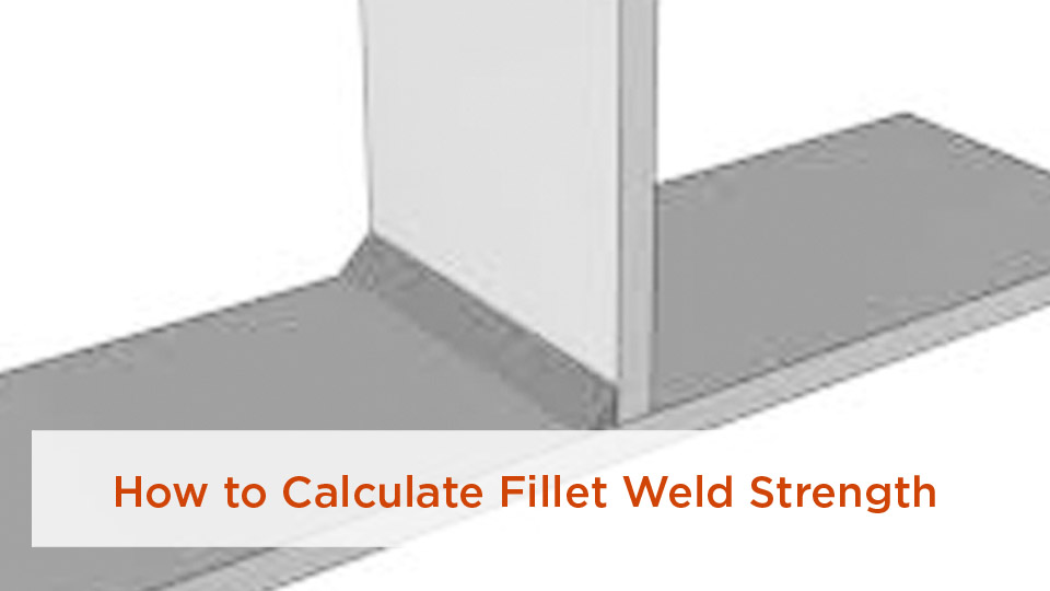
One of the first challenges I ran into as a new welder was figuring out the maximum fillet weld size for plate thickness. I once laid down a heavy bead on 1/4-inch plate, thinking more filler metal automatically meant a stronger joint. Instead, I used extra wire, added cleanup, and put more heat into the work without proving that the connection needed the added weld metal. The right size comes from the governing code, the joint geometry, the required strength, and the welding procedure—not from bead size alone.
Quick Answer
For a fillet weld placed along the edge of structural-steel plate, use the edge thickness as the geometric cap. If the edge is under 1/4 in., the maximum is the full thickness. At 1/4 in. or thicker, the maximum is usually the thickness minus 1/16 in., unless the drawing specifically calls for a built-out full-throat weld.
Key Takeaways
- Edge maximum: For material under 1/4 in., the fillet leg may equal the edge thickness. For material 1/4 in. and thicker, the usual maximum is thickness minus 1/16 in.
- Minimum size: The familiar structural-steel minimums are 1/8, 3/16, 1/4, and 5/16 in. as the governing plate-thickness range increases.
- Maximum is not the design size: Loads, effective weld length, filler-metal strength, base-metal limit states, fatigue, drawings, and the WPS can require a different joint or a larger calculated throat.
- Throat controls weld-metal area: For an ideal equal-leg fillet in a 90-degree joint, the theoretical throat is about 0.707 times the leg size.
- Process affects execution: MIG/GMAW, TIG/GTAW, and stick/SMAW settings must follow the qualified or approved WPS; the process does not erase the geometric edge limit.
At a Glance
| Time Required | About 5–15 minutes to check the permitted size range before welding |
| Difficulty | Intermediate; engineered or code work requires approved drawings and a WPS |
| Tools Needed | Calipers or a rule, project drawings, applicable code/WPS, calculator, and a fillet weld gauge |
| Cost | No added material cost for the calculation; a weld gauge is the main special tool if one is not already available |
Warning: These sizing rules are for structural-steel work governed by the cited AISC/AWS provisions. Do not transfer them unchanged to aluminum, stainless steel, sheet steel, pressure vessels, bridges, or another code. Before welding, use the required helmet, eye and skin protection, control sparks and combustibles, and provide ventilation or fume control—especially when coatings such as galvanizing are present.
Maximum Fillet Weld Size Rules for Plate Thickness
The maximum fillet weld size is not a universal “strongest weld” number. For structural steel, the ANSI/AISC 360-22 Specification sets design limits, while the current AWS D1.1/D1.1M:2025-AMD1 Structural Welding Code—Steel governs welding, qualification, fabrication, and inspection when the contract invokes it. D1.1 is written for common carbon and low-alloy constructional steels rather than every weldable metal. The project drawings and WPS remain controlling documents.
Plate thickness sets the geometric ceiling along an edge; it does not, by itself, prove that a weld is strong enough for the load.
Products Worth Considering

Package Includes: you will receive 3 piece welding measuring tools, including 1 piece single fillet weld depth gauge measured 4.72 x 1.26 inches/ 12 x 3.2 cm in length and width, 0.04 inches/ 1 mm in thickness, 1 piece 7 piece fillet weld gauge set measured 4.33 x 1.26 inches/ 11 x 3.2 cm in length and width, 0.31 inches/ 8 mm in thickness, and 1 piece bridge cam welding gauge measured 3.94 x 2.76 inches/ 10 x 7 cm in length and width, and 0.51 inches/ 1.3 cm in thickness

Popular Weld Measuring Fillet Gauges: Fillet Weld Leg, Throat and Theoretical Throat

Durable: Made of high-quality 304 stainless steel, this gauge set has great rust resistance and wear resistance.
What Determines the Maximum Fillet Weld Size for Your Plate Thickness?
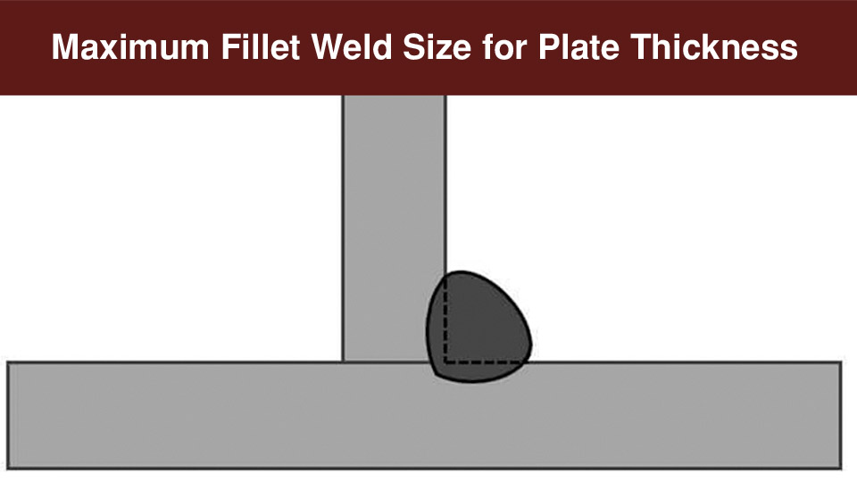
For a fillet weld deposited along the edge of a connected part, the edge thickness controls the geometric maximum. If the edge is less than 1/4 in. thick, the specified fillet weld must not be larger than that thickness. If the edge is 1/4 in. or thicker, the usual maximum is the thickness minus 1/16 in.
The 1/16-in. setback leaves the original edge visible. That helps prevent an edge from being melted away and mistaken for a full-size weld that does not have the required throat. A full-throat built-out weld can be used only when the design drawing specifically calls for that detail.
Why Should You Care About Limiting Fillet Weld Size Based on Plate Thickness?
Right-sizing the weld controls heat input, filler use, fabrication time, and distortion. A larger weld can increase weld-metal area, but it may not increase the connection’s usable capacity if the base metal, weld length, fatigue detail, or another limit state governs. Oversized welds are not automatically rejectable; their profile and effect on the finished member still have to meet the applicable acceptance rules.
Breaking Down Fillet Weld Anatomy: Leg Size, Throat, and Plate Thickness
The leg size is measured from the joint root to the weld toe along each connected surface. The theoretical throat is the shortest distance from the root to the face of the diagrammatic weld. For an equal-leg fillet in a 90-degree joint:
Theoretical throat ≈ 0.707 × leg size
That shortcut does not automatically apply to unequal-leg fillets, skewed T-joints, flare welds, or profiles that fail to contain the required inscribed triangle. The drawing and applicable code define which dimension must be measured.
AISC and AWS Rules for Minimum and Maximum Fillet Weld Sizing
The edge maximum and the minimum weld-size table answer different questions. The maximum protects the edge geometry. The minimum is a fabrication floor intended to support sound welding; it is not a substitute for a strength calculation. The required weld must satisfy the design, the minimum table, the edge maximum, and any stricter WPS or project requirement.
| Thickness of Thinner Connected Part (in.) | Minimum Fillet Leg (in.) | Maximum Along an Edge |
|---|---|---|
| Up to 1/4 | 1/8 | Equal to the edge thickness when the edge is under 1/4 in.; 3/16 in. when the edge is exactly 1/4 in. |
| Over 1/4 to 1/2 | 3/16 | Edge thickness minus 1/16 |
| Over 1/2 to 3/4 | 1/4 | Edge thickness minus 1/16 |
| Over 3/4 | 5/16 | Edge thickness minus 1/16 |
Note: The table gives a code floor and an edge ceiling, not an approved final weld size. If the strength calculation requires a weld outside that range, the connection must be redesigned or specifically detailed rather than improvised at the machine.
Worked Examples: Common Plate Thicknesses
- 3/16-in. edge: The table minimum is 1/8 in., and the edge maximum is 3/16 in.
- 1/4-in. edge: The table minimum is 1/8 in., but the standard edge maximum drops to 3/16 in. because the 1/16-in. setback applies at 1/4 in. and thicker.
- 3/8-in. edge: The table minimum is 3/16 in., and the edge maximum is 5/16 in.
- 1/2-in. edge: The table minimum is 3/16 in., and the edge maximum is 7/16 in.
- 3/4-in. edge: The table minimum is 1/4 in., and the edge maximum is 11/16 in.
Each range still has to be checked against the required load, weld length, filler classification, base-metal strength, loading direction, fatigue category, and project details.
When Does Plate Thickness Dictate a Smaller Fillet Weld? Real-World Scenarios
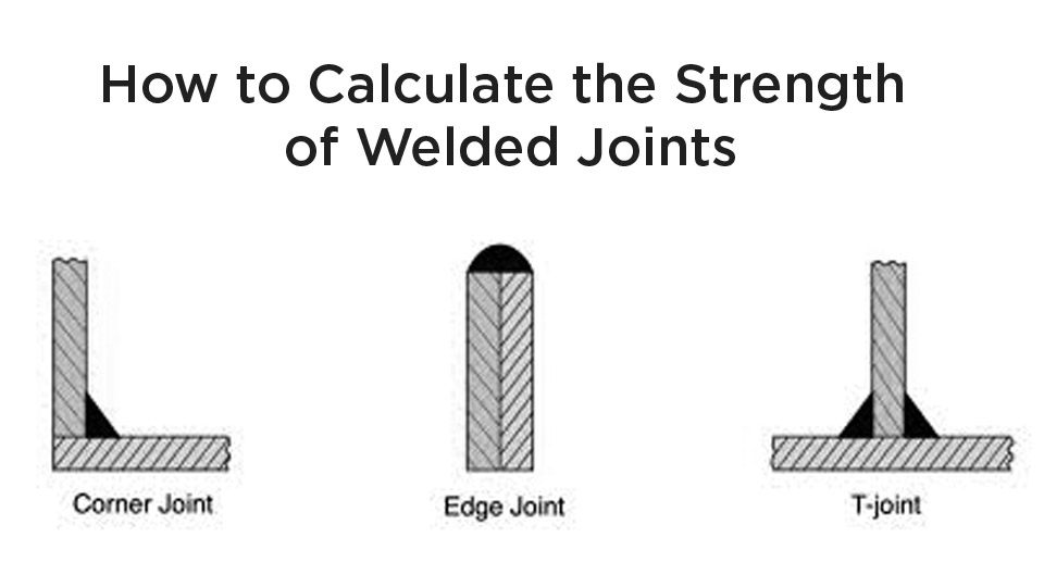
Lap joints and corner details with a weld along a free edge are the classic cases for the edge maximum. A T-joint with welds placed on the broad faces of the plates is not controlled by the same visible-edge setback, but that does not make any weld size acceptable. The engineer still has to check the weld and connected material, and the fabricator still has to follow the WPS.
Do not apply the structural-steel chart unchanged to stainless steel, aluminum, thin sheet, bridge work, pressure systems, or equipment governed by another standard. Those applications can use different material rules, qualification requirements, and acceptance criteria.
Step-by-Step: How to Calculate and Apply the Maximum Fillet Weld Size
- Identify the governing documents. Check the design drawings, contract specification, applicable welding code, and WPS before using a generic chart.
- Measure both connected parts. Record the thickness of the part whose free edge will receive the weld and the thickness used by the applicable minimum-size table.
- Identify the joint geometry. Decide whether the weld runs along a free edge, as in many lap or corner details, or lies on plate faces, as in many T-joints.
- Apply the edge maximum. Use the full edge thickness below 1/4 in. or edge thickness minus 1/16 in. at 1/4 in. and above, unless a built-out full-throat detail is specifically shown.
- Check the minimum and required size. Compare the code minimum with the size required by the engineered load calculation. The larger requirement normally governs, provided it does not violate the edge maximum.
- Check the throat and effective length. For a 90-degree equal-leg fillet, estimate the theoretical throat as 0.707 times the leg, then verify the actual code provisions for the joint and loading.
- Confirm fit-up and parameters. Use the WPS for joint preparation, root opening, preheat, filler metal, position, voltage, amperage, wire feed, travel speed, and pass sequence.
- Weld, clean, and inspect. Measure several locations with the correct fillet gauge and check the profile, toes, terminations, and visible discontinuities against the project acceptance criteria.
Pro Tip: Write down the allowable range before striking an arc. For a 3/8-in. edge, for example, “3/16 minimum, 5/16 edge maximum” is more useful than trying to judge the bead by eye after the joint is hot.
Products Worth Considering

7piece Fillet Weld Set Gage Rl Gauge

12piece Fillet Weld Set Gage Rl Gauge

【7 pieces Weld Fillet Gauges】: 7 pieces weld fillet gauges are held by bolt and nut that can be disassembled, each weld gauge can be used to check the size of fillet legs and fillet throats
Common Mistakes and Quick Fixes
| Mistake | Why It Matters | Better Fix |
|---|---|---|
| Treating the maximum as the target | Adds metal and heat without proving that the load path needs it | Use the specified or calculated size within the permitted range |
| Calling an undersized weld “lack of fusion” | Undersize and incomplete fusion are different conditions with different acceptance rules | Measure size and inspect fusion/profile separately |
| Ignoring the built-out exception | A full-throat edge detail must be intentionally designed and shown | Follow the drawing; never assume the exception in the shop |
| Using one chart for every metal | Different materials and industries use different codes and procedures | Confirm material, service, code, and WPS first |
| Grinding off harmless excess metal automatically | Unneeded removal can introduce gouges, extra heat, shrinkage, or repair work | Have the inspector evaluate profile and end-use interference before repair |
Best Practices for Fit-Up and Prep Across Thicknesses
Fillet-weld joint preparation is controlled by the WPS and the actual joint—not by a blanket rule that thick plate always needs a bevel. Remove moisture, oil, paint, scale, and other material that would interfere with welding, using methods permitted by the procedure and coating requirements.
The AISC fillet-weld FAQ notes that a root opening up to 1/16 in. can be accepted without modification under the cited AWS provision. Larger openings can require an increase in weld size or proof that the required effective throat was achieved. Never compensate for poor fit-up by guessing.
Machine Settings for Cleaner Fillet Welds
Use the WPS first. If the work is not code-governed and no WPS exists, use the machine and filler-metal manufacturer’s chart as a starting point, make a test weld on matching scrap, and verify fusion and profile before welding the part. The Miller weld-setting calculators cover common MIG, flux-cored, stick, and TIG starting ranges, but they do not replace engineering or procedure qualification.
Process selection changes how the weld is deposited, not the required design throat. Short-circuit GMAW or GTAW may offer useful heat control on thinner noncritical work, while SMAW, FCAW, spray-transfer GMAW, or multi-pass procedures may suit thicker work. Code projects must use a process, transfer mode, filler, position, and parameter range permitted by the WPS.
Fillet Welds in Trailers, Frames, and Structural Builds
Fillet Welds in Everyday Applications: Trailers, Frames, and Structural Builds
On trailers and frames, right-sizing welds can reduce distortion and filler use, but these parts often see vibration, impact, and repeated loading. Do not design a road-going trailer or load-bearing frame from the plate-thickness chart alone. Use engineered details, verify the governing vehicle or structural requirements, and follow a qualified or approved procedure where required.
Pros and Cons of Pushing Fillet Weld Limits on Thicker Plates
A larger effective throat increases weld-metal area, but the connection may still be governed by the base metal, eccentric loading, fatigue, or effective length. Larger single-pass welds may also be impractical in a given process or position. When the required size approaches or exceeds the edge maximum, better options can include more effective weld length, welding both sides when the design permits it, changing the connection geometry, using thicker material, or specifying a groove weld.
Advanced Tips: Multi-Pass Fillets and Filler Selection
Use multiple passes when the WPS requires them to build the specified fillet size and maintain an acceptable profile. Clean between passes, control interpass temperature, and follow the required sequence to limit distortion. Match filler metal to the WPS and base material. For low-hydrogen electrodes, follow the manufacturer’s storage, exposure, and permitted reconditioning instructions; do not invent a baking temperature or time.
Note: If the calculated weld will not fit within the permitted edge geometry, stop and change the detail. Adding a wider bead without an approved design can hide the edge, increase distortion, and still fail to provide the intended load path.
Conclusion
Always separate three questions: What size does the load require? What minimum does the governing code or WPS require? What maximum will the joint geometry allow? For structural-steel edge fillets, the familiar cap is full thickness below 1/4 in. and thickness minus 1/16 in. at 1/4 in. and above, unless the drawing specifically details a built-out full-throat weld. Measure the finished weld, follow the WPS, and let the approved design—not bead appearance—set the target.
Frequently Asked Questions
What is the maximum fillet weld size for 1/4-inch plate?
For a fillet weld along the 1/4-in. edge, the usual maximum is 3/16 in. because the plate is at the threshold where the 1/16-in. setback applies. A specifically detailed built-out full-throat weld is an exception; do not assume that exception without the drawing.
What is the minimum fillet weld size for a 1/2-inch plate?
The familiar structural-steel table minimum is 3/16 in. for the “over 1/4 through 1/2 in.” range. That answer assumes the table applies to the joint and loading. The design, cyclic-loading provisions, WPS, preheat requirements, or project specification may require more.
Can I weld a fillet larger than the plate thickness?
Do not specify a larger weld along a free edge by default. The standard edge rule limits the weld to the edge thickness below 1/4 in. and to thickness minus 1/16 in. at 1/4 in. and above. A drawing may intentionally specify a built-out full-throat detail. Face-welded T-joints have different geometry but still require design checks.
Why do fillet welds cause warping or distortion?
The weld and nearby base metal expand while hot and shrink as they cool. An oversized weld, an unbalanced sequence, poor restraint, or excessive heat input can increase angular distortion and residual stress. Use the WPS, balanced sequencing, suitable fixturing, and only the weld size the design requires.
How do I measure fillet weld size accurately?
Clean the weld and use the correct fillet gauge at several locations. Check the required leg size and, when applicable, the throat/profile gauge. The 0.707 shortcut describes an ideal equal-leg 90-degree fillet; it does not excuse a concave profile or unequal geometry that fails to contain the required diagrammatic weld.
What welding process is best for thin plate?
There is no universal best process. GMAW short-circuit and GTAW can provide useful heat control on some thin, noncritical work, but material, position, access, productivity, transfer mode, qualification, and code restrictions matter. For code work, use the process and parameter range listed in the WPS.
What should I do if the required fillet weld exceeds the edge maximum?
Do not simply overfill the edge. Have the connection revised. Common engineered options include increasing effective weld length, welding both sides where permitted, changing the joint layout, using thicker material, or specifying a partial- or complete-joint-penetration groove weld.
Sources
- ANSI/AISC 360-22, Specification for Structural Steel Buildings — governing structural-steel design provisions and fillet-weld limits.
- AISC Fillet Welds FAQ — edge melt-back rationale, fit-up, oversize, profile, and repair guidance.
- AWS D1.1/D1.1M:2025-AMD1, Structural Welding Code—Steel — current structural-steel welding, qualification, fabrication, and inspection code.
- ANSI Z49.1:2021, Safety in Welding, Cutting, and Allied Processes — welding safety, ventilation, fire prevention, and personnel protection.
- OSHA 29 CFR 1910.252 — welding fire prevention, eye and face protection, protective clothing, and ventilation requirements.
- Miller Weld-Setting Calculators — manufacturer starting ranges for common welding processes.