When my stick welder refused to strike an arc, I quickly realized how fast a simple job can turn into pure frustration. The metal is cleaned, the electrodes are ready, and the machine appears to be powered, yet the rod only sticks, throws a weak spark, or does nothing at all. In most cases, the problem is somewhere in the input power, weld circuit, machine setup, electrode, or arc-start technique.
Getting the arc started is not only about convenience. A steady arc affects penetration, fusion, bead shape, and safety. This guide walks through the checks I use when a stick welder is not arcing, starting with the simple setup problems before moving to faults that need qualified service.
Quick Answer
If a stick welder will not strike an arc, confirm it is in Stick/SMAW mode and its weld output is enabled. Then check the input supply, cable connections, work-clamp contact, polarity, electrode type and condition, and amperage. If it still has no output, let it cool and consult the manual or a qualified repair technician.

Image credit: worthyhardware
Key Takeaways
- A powered fan or display does not prove that weld output is enabled or reaching the electrode.
- The work clamp must contact clean bare metal and every cable connection must be tight.
- Polarity, electrode classification, diameter, moisture condition, and machine capability must match.
- Low amperage commonly causes sticking, but an oversized rod, long leads, weak input power, or poor contact can feel similar.
- Stop troubleshooting and use qualified service if leads are damaged, the machine repeatedly overheats, or there is still no output after the external checks.
At a Glance
| Time Required | About 10–30 minutes for external checks |
| Difficulty | Beginner to intermediate; internal electrical work requires a qualified technician |
| Tools Needed | Welder manual, wire brush or grinder, dry compatible electrodes, insulated gloves, and basic hand tools for external connectors |
| Cost | Often no cost if the issue is setup-related; replacement electrodes, clamps, leads, or professional repair add cost |
Warning: Stick-welder output can cause a serious or fatal shock. Keep gloves and clothing dry, stay out of wet conditions, and turn off and disconnect input power before tightening leads or removing covers. Do not probe an energized receptacle or open the welder unless you are qualified to service electrical equipment.
Why Your Stick Welder Is Not Arcing
Shielded metal arc welding, or SMAW, normally uses a constant-current power source to form an arc between the electrode and the workpiece. The arc can start only when the machine has suitable open-circuit voltage, weld output is enabled, and the electrode and work lead complete the circuit.
The first clue is the exact symptom. A rod that never produces a spark has a different problem from a rod that sparks and immediately freezes to the plate.
| Symptom | Likely Causes | First Check |
|---|---|---|
| No spark at all | Output disabled, wrong process mode, open cable, loose connector, thermal shutdown, or internal fault | Select Stick/SMAW, enable local output, and inspect both leads |
| Brief spark, then the rod sticks | Amperage too low, rod too large, poor work-clamp contact, wrong polarity, weak input, or hesitant technique | Use the package amperage range and clamp directly to bare metal |
| Arc starts, sputters, and dies | Loose connection, contaminated surface, long arc, damp or damaged rod, unstable generator, or low-line condition | Tighten connections, try a fresh rod, and shorten the arc |
| Works briefly, then stops | Duty cycle exceeded, blocked airflow, thermal protection, or intermittent cable fault | Check the thermal light and allow the fan to cool the machine |
| Only one electrode type fails | Wrong polarity, unsuitable open-circuit voltage, unsupported E6010 operation, or electrode damage | Check the rod package and the welder’s approved-electrode list |
| Arc bends or wanders | Magnetic arc blow | Move the work connection, shorten the arc, lower current, or use AC if permitted |
A fan, power light, or digital display only confirms that part of the machine has power. It does not prove that welding current is reaching the electrode holder.
Checking Your Power Supply
The first thing I check is the machine’s rating plate and input-power section in the manual. Portable stick welders commonly use 120-volt, 240-volt, or dual-voltage input, while larger machines may require other voltages and phases. The receptacle, plug, branch circuit, breaker, conductor size, and grounding method must match that specific welder.
Do not assume that every 120-volt machine belongs on the same 20-amp circuit. Some models can run at reduced output on a standard circuit, while others require a larger dedicated branch circuit for full performance. The correct values are listed in the manual’s electrical-service guide. Manufacturer manuals are available through resources such as the Miller manuals and parts portal.
Also keep input amperage separate from welding amperage. A machine set to produce 80 amps at the electrode is not simply drawing 80 amps from the wall. Efficiency, duty cycle, input voltage, power factor, and the selected output all affect the input current.
Look for these practical warning signs:
- The breaker trips as soon as you try to strike an arc.
- The plug or receptacle becomes hot, discolored, loose, or smells burned.
- Garage lights dim severely every time the electrode touches the work.
- The welder displays a low-line, input-voltage, or overcurrent error.
- The machine works on 240 volts but performs poorly on 120 volts at the same requested output.
If the supply appears questionable, stop and have a qualified electrician inspect the circuit. A beginner should not remove a receptacle cover or probe an energized outlet with a multimeter.
An extension cord can also create voltage drop. I once used a thin 50-foot cord on a job site and spent half the morning sticking rods. Use an extension cord only if the welder manufacturer permits it. Match the cord’s conductor size, length, temperature rating, plug, and current rating to the manual, and keep it as short as practical.
For an engine-driven generator, verify that it can provide the continuous wattage, voltage, frequency, and waveform quality required by the welder. A generator that advertises enough peak watts may still sag when the arc starts.
Note: A breaker that repeatedly trips is not an invitation to install a larger breaker. The breaker protects the branch-circuit wiring. Any circuit change must match the conductor size, receptacle, welder manual, electrical code, and local requirements.
Inspecting Your Connections
Loose, dirty, undersized, or damaged connections are among the most common causes of a weak or missing arc. The welding circuit includes the electrode holder, electrode lead, output connectors, work lead, work clamp, workpiece, and every connection between them.
The clamp on the work lead is technically the work clamp, although many people call it a ground clamp. It completes the welding circuit; it does not replace the safety-grounding conductor in the machine’s input cord.
With input power turned off, check the following:
- Seat and twist-lock all Dinse, Twist-Mate, lug, or terminal connections fully.
- Clamp to clean bare metal as close to the weld as practical.
- Do not depend on rusty hinges, painted tables, bolted joints, or dirty bearings to carry welding current.
- Make sure the electrode holder grips the rod firmly without a loose jaw or burned contact.
- Inspect both leads for crushed areas, cuts, exposed conductor, brittle insulation, and overheated connectors.
- Spread out tightly coiled welding cable so it does not build excess heat.
OSHA requires the work lead to be firmly attached and calls for damaged leads with exposed conductors to be replaced rather than left as a makeshift repair. See 29 CFR 1910.254 and the related OSHA interpretation on damaged welding leads.
A connection that becomes hot quickly deserves attention. Heat at the clamp, connector, or cable lug often points to high resistance, poor contact, corrosion, looseness, or a component that is too small for the amperage and duty cycle.
Pro Tip: When the arc is weak, clamp directly to the workpiece instead of the far side of the welding table. That simple change rules out paint, rust, loose table joints, and poor electrical continuity through fixtures.
Choosing the Right Electrode
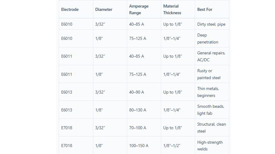
The electrode must match the power source, polarity, base metal, position, and available amperage. Common mild-steel electrodes include E6010, E6011, E6013, and E7018, but the package or manufacturer data sheet is the final authority.
| Electrode | Typical Polarity | Common Use | Starting Behavior | Important Note |
|---|---|---|---|---|
| E6010 | DCEP, also written DC+ | Deep penetration, root passes, and less-than-perfect steel | Forceful arc; some small inverters do not run it well | Confirm that the machine specifically supports E6010 |
| E6011 | AC or DCEP; some products also list DCEN | Repair work, rusty steel, and AC transformer welders | Forceful but generally suitable for AC machines | Check the exact package polarity |
| E6013 | AC, DCEP, or DCEN depending on product | Clean thinner steel, short welds, and practice | Usually easy and smooth | Slag can cover the puddle if travel or angle is wrong |
| E7018 or E7018AC | Usually DCEP or AC as listed by the manufacturer | Clean steel and structural applications | Smooth and stable with a very tight arc | Requires controlled moisture handling for low-hydrogen work |
Lincoln Electric’s electrode-classification guide explains how the final classification digit relates to coating and usable current. Always verify the exact manufacturer data because individual products can have narrower operating limits.
If an AC-only machine will not run E6010, that does not automatically mean the welder is broken. E6010 is normally a DCEP electrode. E6011 gives similar digging action while operating on AC and is often a better match for an older AC transformer machine.
Low open-circuit voltage can also matter. Some electrodes are designed to start more easily on low-OCV AC machines. If standard E7018 is difficult on an older AC welder, use an E7018AC product approved for the machine rather than assuming every E7018 will behave the same.
Electrode diameter matters too. A small 120-volt inverter may run a 3/32-inch rod well but struggle to start a 1/8-inch or 5/32-inch rod at the required current. Use a smaller diameter within the electrode manufacturer’s range when the machine is near its limit.
Products Worth Considering

MODEL: E6013 is a mild-steel general purpose rod. It operates on AC or DC welding current and works well on low voltage AC machines.

Product Introduction: E6013 welding rod is suitable for both AC and DC applications and can be used for all position welding

Premium quality ER70S-6 mild steel alloy copper coated TIG welding rods; diameter 0.045", 1/16", 3/32" and 1/8" with 36" length. Package of 5-Lb and 10-Lb.
Checking Electrode Condition and Storage
I once grabbed E7018 rods that had sat in a damp garage for months. The coating looked acceptable at first, but the starts were inconsistent and the weld quality was poor. Moisture-sensitive rods need more care than an open cardboard box on a garage shelf can provide.
E7018 electrodes normally ship in sealed packaging. Once opened, low-hydrogen work may require a controlled holding oven and limited atmospheric exposure. A common holding range for many E7018 products is 250–300°F, but the exact requirement comes from the electrode data sheet, welding procedure, and applicable code. Reconditioning is a separate process and may require a much higher temperature.
Hobart’s stick-electrode storage guide lists 250–300°F as a holding range for opened E7018-class electrodes and 500–800°F for certain reconditioning procedures. The same guide says cellulosic electrodes such as E6010 and E6011 should remain dry at room temperature, should not be reconditioned, and should not be stored above 130°F.
For casual non-code practice, replacing rods with cracked, contaminated, crumbling, or obviously damp flux is usually safer than trying to invent a drying cycle. Never use a kitchen oven that will later be used for food. Use equipment intended for electrode storage and follow the rod manufacturer’s directions.
A used E7018 electrode may also develop a glassy deposit at the tip. Let it cool, then remove the deposit as the manufacturer recommends before trying to restart. Do not strip off a long section of flux or expose more core wire than necessary.
Adjusting Machine Settings
Improper settings can make a good machine feel broken. Start by selecting Stick or SMAW mode. On a multiprocess welder, confirm that it is not still in TIG, MIG, gouging, remote, or standby mode. Some machines also have an output-on control that must be enabled before the electrode holder becomes live.
Next, check polarity. DCEP means the electrode holder is connected to the positive output and the work lead to the negative output. DCEN reverses those connections. AC has no fixed positive or negative side. Follow the electrode package rather than relying on cable color alone.
Set amperage from the range printed on the electrode package. As examples, current Lincoln data for a 3/32-inch E6011 product lists roughly 40–90 amps on AC, while Hobart’s E7018 guidance gives about 90–150 amps for a 1/8-inch rod. Those are starting references, not universal settings. Position, joint design, machine behavior, and the exact product can narrow the useful range.
If the electrode sticks during a proper strike, raise the amperage in small steps while staying inside the manufacturer’s range. If the puddle becomes excessively fluid, spatter increases sharply, undercut appears, or the electrode overheats, the setting may be too high. Miller’s stick-welding technique guide describes the common signs of amperage that is too low or too high.
Hot start briefly adds current during ignition, while arc force or dig adds current as the arc voltage falls and the electrode approaches a short circuit. These controls can reduce sticking, but their scales are not standardized. My own preferred numbers on one machine may be wrong on another. Start at the manufacturer’s default or middle setting and adjust one control at a time.
Pro Tip: Change only one variable at a time. If you change polarity, amperage, hot start, arc force, rod size, and technique together, you will not know which change solved the problem.
Striking the Arc Properly
The two basic methods are tap starting and scratch starting. With a tap start, touch the rod briefly to the work and lift it just enough to establish the arc. With a scratch start, move the tip across the plate like striking a match, then lift into the correct arc length.
Hesitation is what caused many of my early stuck rods. The contact should be quick. If the electrode freezes to the plate, snap the holder back to break it free. If it will not release immediately, switch off the weld output before touching or loosening anything. Do not grab a hot electrode with bare hands.
Arc length depends on the rod. E7018 wants an especially tight arc, with the electrode almost riding on the puddle. E6010 and E6011 use a more forceful arc and may be manipulated differently. A long arc increases instability, spatter, porosity risk, and arc blow.
Practice on clean scrap using the same rod, polarity, and amperage planned for the job. A few controlled starts on scrap can reveal a setup problem before it damages the actual joint.
Cleaning the Workpiece
A dirty workpiece can block work-clamp contact and make the arc unstable. Rust, paint, powder coating, scale, grease, and dirt also increase the risk of porosity, inclusions, lack of fusion, and hazardous fumes.
Clean both the weld area and the work-clamp contact point. Use a dedicated wire brush for light contamination and a grinder where heavier rust, paint, or scale must be removed. Confirm that the base metal and coating can be welded safely before striking an arc.
For grease, use a non-chlorinated cleaner that is suitable for the metal, follow its safety data sheet, ventilate the area, and allow the surface to dry completely. Remove the cleaner and its vapors from the welding area before starting.
Warning: Never weld near chlorinated brake cleaner, chlorinated degreaser, or metal that is still contaminated with a chlorinated solvent. Heat and ultraviolet radiation from the arc can contribute to phosgene formation. Painted, plated, galvanized, and coated metals may also release hazardous fumes and need coating-specific controls.
Dealing with Arc Blow
Arc blow is magnetic deflection of the arc. Instead of staying centered, the arc bends, wanders, pushes the puddle, or becomes difficult to control. It is most common with DC welding near the ends of joints, corners, large steel masses, or magnetized parts.
I ran into it while welding a heavy beam. The machine had output and the rod would start, but the arc kept pulling away from the joint. That distinction matters: arc blow normally causes a wandering or unstable arc rather than a completely dead electrode.
Try these corrections:
- Move the work clamp so welding current flows away from the troublesome area.
- Place the work connection closer to the joint while maintaining safe access.
- Use a shorter arc.
- Reduce current and use a smaller electrode if the procedure allows it.
- Change travel direction or weld toward an existing tack or completed weld.
- Use AC when the electrode, machine, and procedure allow it.
- Demagnetize the workpiece when residual magnetism is the cause.
Lincoln Electric explains that AC markedly reduces arc blow because the current reverses rapidly. See Prevent Arc Blow for additional current-path techniques.
Machine-Specific Issues
When the external setup checks out, look for machine-specific controls and protection features before assuming that an internal component has failed.
- Wrong mode: Select Stick/SMAW rather than TIG, MIG, or another process.
- Remote mode: A machine waiting for a remote command may not energize its output from the panel.
- Output disabled: Some welders have a separate output-on, contactor, or standby control.
- Anti-stick operation: Some inverters intentionally cut current after detecting a stuck electrode. Remove the rod, reset the output if needed, and try again.
- Thermal shutdown: A thermal light or error code means the duty cycle may have been exceeded. Leave the machine powered as directed so the fan can cool it.
- Blocked cooling: Dust, restricted vents, or a failed fan can trigger protection early.
- Engine-drive idle: An engine-driven unit may need to reach weld or high-idle speed before delivering normal output.
- Internal fault: A failed relay, output device, rectifier, control board, transformer connection, sensor, or selector can produce a powered display with no welding output.
Do not open the machine merely because the fan runs but the rod will not arc. Capacitors can retain dangerous energy after input power is removed. Use the model-specific troubleshooting chart, record any error code, and contact an authorized service center when the fault is inside the case.
Step-by-Step Troubleshooting Guide
Use this order so you solve simple external problems before moving toward electrical service:
- Make the area safe: Remove combustibles, wear dry PPE, and keep the machine and floor dry.
- Confirm the process: Select Stick/SMAW, local or panel control, and output-on as required.
- Check input requirements: Match the plug, receptacle, voltage, branch circuit, and generator to the rating plate and manual.
- Allow for cooling: If a thermal light is on, stop welding and let the machine cool according to its manual.
- Inspect external leads: With input power off, tighten output connectors and check the holder, work clamp, and cable insulation.
- Move the work clamp: Attach it directly to clean bare metal close to the weld.
- Verify polarity: Match DCEP, DCEN, or AC to the exact electrode package.
- Use a compatible rod: Confirm electrode classification, diameter, machine capability, and open-circuit-voltage suitability.
- Try a fresh electrode: Replace rods with damaged, contaminated, or suspect flux.
- Set package amperage: Begin near the lower-middle part of the recommended range and adjust in small steps.
- Use a quick start: Tap or scratch without pausing, then maintain the rod-specific arc length.
- Test on clean scrap: This separates machine and technique issues from joint contamination.
- Address arc blow: Reposition the work connection, shorten the arc, lower current, or use AC when allowed.
- Stop at the service boundary: If there is still no output, document the symptoms and have the machine inspected by a qualified technician.
Common Mistakes and Fixes
| Mistake | Fix |
|---|---|
| Using a damp, cracked, or contaminated rod | Use a fresh electrode and follow the product-specific storage instructions |
| Assuming every E7018 uses the same oven cycle | Separate holding from reconditioning and follow the data sheet, WPS, and code |
| Setting amperage too low | Increase current gradually while staying within the rod manufacturer’s range |
| Using a rod that is too large for the machine | Switch to a smaller diameter that the welder can run at its required amperage |
| Clamping to paint, rust, or a distant table leg | Clamp directly to clean bare metal on the workpiece |
| Using the wrong polarity | Read the electrode package and reconnect the leads with input power off |
| Hesitating during the arc strike | Use a quick tap or scratch and lift immediately into the correct arc length |
| Treating a thermal shutdown as a failed machine | Check the duty cycle and let the cooling system complete its cycle |
| Taping over exposed welding-lead conductor | Remove the lead from service and replace or professionally repair it as permitted |
Safety Considerations
A missing or unstable arc can tempt you to keep touching the electrode to the work while changing controls. Slow down. The electrode holder may be electrically live whenever weld output is enabled, and a stuck rod can heat rapidly.
- Wear dry welding gloves, flame-resistant clothing, safety glasses with side protection, and a welding helmet.
- Use a filter shade appropriate for the process, electrode size, and current. OSHA lists minimum SMAW shades of 7 below 60 amps, 8 at 60–160 amps, 10 above 160–250 amps, and 11 above 250–550 amps. Start darker and lighten only enough to see the weld zone clearly. See OSHA 29 CFR 1910.133.
- Keep your body insulated from the work and ground, especially in damp, confined, or conductive locations.
- Do not use damaged electrode holders, plugs, receptacles, work clamps, or leads.
- Keep combustible material away and have suitable fire-control equipment available.
- Do not weld a drum, tank, pipe, or closed container unless it has been properly cleaned, tested, vented, and prepared under an approved hot-work procedure.
- Use local exhaust or other ventilation appropriate to the electrode, base metal, coating, and work area. Keep your head out of the fume plume.
- Remove chlorinated solvents and their vapors from the welding area.
- Protect nearby people with screens and suitable eye protection.
- Disconnect input power before changing internal connections or opening any access panel.
OSHA’s general welding requirements address fire prevention, eye protection, ventilation, and hazardous materials. Electrical installation and machine grounding must also follow the welder manual and applicable electrical rules.
Conclusion
A stick welder that will not arc usually has a problem with output selection, input power, cable contact, polarity, electrode compatibility, amperage, or starting technique. Start with the work clamp and process settings, because those checks are fast and solve a surprising number of failures.
If the machine produces no spark after you verify the external circuit with known-good leads and a compatible electrode, stop there. Record the mode, polarity, amperage, error lights, input voltage, and exact symptom, then give that information to a qualified repair technician. That approach protects you from shock and prevents a small setup issue from turning into damaged equipment or an unsafe weld.
Frequently Asked Questions
Why does my stick welder stick instead of arc?
The usual causes are amperage that is too low, a rod that is too large, poor work-clamp contact, wrong polarity, a weak input supply, or hesitation during the strike. Clamp directly to bare metal, verify the rod’s amperage and polarity, and use a quick tap or scratch motion.
Can I use E6010 rods on an AC welder?
Standard E6010 electrodes normally require DCEP, so they are not a suitable choice for an AC-only welder. E6011 is designed to operate on AC and provides similar deep, forceful penetration for many repair jobs. Confirm the polarity printed on the exact electrode package.
Can a bad work clamp cause no arc?
Yes. Paint, rust, loose jaws, burned contacts, a broken conductor, or a poor cable-to-clamp connection can leave the circuit open or create enough resistance to weaken the arc. Attach a known-good clamp directly to clean bare metal near the weld.
Why is the fan running when the welder has no output?
The control and cooling circuits can operate even when weld output is disabled. Check Stick/SMAW mode, local or remote control, output enable, thermal indicators, error codes, and external leads. Continued zero output after those checks may indicate an internal fault.
How do I know whether the power supply is the problem?
Check the machine rating plate, plug, receptacle, breaker, extension-cord requirements, and any low-line error. Repeated breaker trips, a hot or discolored plug, severe light dimming, or poor performance only at high output can point to the supply. Have a qualified electrician perform energized testing.
What is the easiest stick electrode for a beginner?
E6013 is often easy to start and produces a smooth arc on clean steel. E6011 is useful when deeper penetration or AC compatibility is needed, while E7018 is smooth but requires a tight arc and more careful moisture handling. Match the rod to the joint rather than choosing only by ease of use.
Can I dry E7018 rods in a household oven?
Do not use an oven that will later prepare food. Low-hydrogen storage and reconditioning require dedicated equipment, controlled temperatures, and product-specific instructions. A common holding temperature is not automatically the correct rebaking cycle for a damp electrode.
How can I reduce arc blow?
Move the work connection to change the current path, shorten the arc, lower the current, use a smaller rod, alter travel direction, or switch to AC when the electrode and procedure permit it. Strong residual magnetism may require demagnetizing the workpiece.
Sources
- Miller — Five Steps to Improving Your Stick Welding Technique — amperage, work-clamp contact, cleaning, and arc technique
- Lincoln Electric — AWS Electrode Classifications — electrode classification, polarity, and common applications
- Hobart Brothers — E7018 Welding Rod Amperage — E7018 characteristics, operating ranges, technique, and storage
- Lincoln Electric — Prevent Arc Blow — magnetic arc-blow causes and corrections
- OSHA 29 CFR 1910.254 — arc-welding leads, work connections, equipment, and operating precautions
- OSHA 29 CFR 1910.133 — eye and face protection and minimum welding-filter shades