When I first started running beads with stick, one of my biggest headaches was finding the right amperage for each rod and metal thickness. Too little current made the electrode stick and sputter. Too much flattened the puddle, increased undercut, and made thin steel disappear before I could control it.
Every welder has been there—trying to balance electrode type, rod diameter, base metal, joint design, and welding position without wasting half a box of rods. That is where a reliable stick welding amperage chart earns its place beside the machine.
A chart gives you a safe starting range so you can focus on arc length, puddle control, fusion, and travel speed. It also makes it easier to compare stick with MIG or TIG welding in the shop. Disclosure: This article uses affiliate links for some products. As an Amazon Associate, I may earn from qualifying purchases.
Amperage is only one part of a sound weld. The electrode manufacturer, machine manual, joint requirements, polarity, and any approved welding procedure specification must still control the final setting. This guide shows you how to find a practical starting point and adjust it without guessing.
Quick Answer
Start with the electrode manufacturer’s range, then tune the machine in 5- to 10-amp steps. Typical 3/32-inch starting ranges are 50–85 A for E6010, 40–90 A for E6011, 70–115 A for E6013, and 80–100 A for E7018. Polarity, position, fit-up, and machine response still matter.
Key Takeaways
- The range printed on the electrode package or manufacturer data sheet overrides any generic amperage chart.
- Rod diameter sets the broad current range; metal thickness, fit-up, weld position, travel speed, and joint design determine where you work inside that range.
- Adjust current in small 5- to 10-amp steps while watching arc stability, bead shape, slag behavior, and fusion.
- DCEP means the electrode holder is positive. DCEN means the electrode holder is negative. Not every electrode works correctly on every polarity.
- A generic chart must not replace an approved WPS or qualified procedure for structural, pressure, lifting, vehicle-frame, or other critical work.
At a Glance
| Time Required | About 10–20 minutes to prepare scrap, confirm polarity, and test a setting; project welding time varies |
| Difficulty | Beginner to intermediate for practice beads; advanced for overhead, cast iron, structural, and code work |
| Tools Needed | SMAW welder, correct electrodes, work clamp, scrap metal, chipping hammer, wire brush or grinder, welding PPE, and fume control |
| Cost | Usually a few dollars in electrodes and scrap for test beads when the welder and PPE are already owned |
Why Amperage Matters in Stick Welding
Stick welding, formally called shielded metal arc welding or SMAW, depends on a steady current passing through the electrode and the workpiece. The current must be high enough to keep the arc stable and melt both the electrode and the joint faces, but not so high that the puddle becomes uncontrollable.
When amperage is too low, the rod may stick, the arc may repeatedly go out, and the bead may become tall and narrow with poor fusion at the toes. Low current is not the only possible cause, though. A weak work connection, an oversized electrode, poor starting technique, insufficient machine output, or the wrong electrode for the power source can produce similar symptoms.
When amperage is too high, the arc becomes harsh, the puddle gets wide and fluid, and undercut or burn-through becomes more likely. High current also increases heat input, distortion, spatter, and electrode consumption.
I learned that lesson on thin steel when I turned the machine up to compensate for poor technique. Instead of improving the weld, I created a wider puddle, warped the panel, and opened a hole that then had to be patched. The better fix was a smaller electrode, tighter fit-up, shorter welds, and controlled travel.
Warning: A generic amperage chart is only a starting reference. Do not use it as a substitute for an approved welding procedure specification, engineering requirements, inspection, or welder qualification on structural steel, pressure equipment, lifting devices, vehicle frames, roll cages, or other joints whose failure could injure someone.
Understanding Stick Welding Electrode Numbers
Stick electrodes come in different core materials, coatings, diameters, positions, and current requirements. The American Welding Society classification printed on the package helps identify those characteristics.
For a common rod such as E7018:
- E identifies a covered electrode.
- 70 indicates a minimum tensile-strength classification of 70,000 psi for the deposited weld metal under the applicable specification.
- 1 indicates that the electrode is classified for all welding positions, subject to the manufacturer’s instructions and the qualified procedure.
- 8 identifies coating and current characteristics associated with that classification.
Common shop electrodes include:
E6010: A fast-freeze, deep-penetrating electrode normally used on DCEP. It is common for open roots, pipe work, and field repairs where a forceful arc is useful. Although it tolerates scale and contamination better than some rods, the joint should still be cleaned wherever practical.
E6011: Similar in general arc character to E6010 but designed to operate on AC as well as suitable DC polarities specified by the manufacturer. It is useful with AC machines and for maintenance work.
E6013: A rutile-coated electrode with a relatively smooth arc and moderate-to-shallow penetration. It is often easier for beginners to control on clean mild steel and light fabrication, but it still produces slag that must be removed between passes.
E7018: A low-hydrogen, iron-powder electrode used for many structural and higher-strength steel applications. It normally runs with a tight arc and requires proper storage and handling.
E308L-16: A stainless electrode commonly used for compatible 304-series stainless steels. It is not the correct filler for every stainless grade or every stainless-to-carbon-steel joint.
The first electrode choice is just as important as the amp setting. I once used an E7018 on a rusty gate without preparing the joint properly. The bead looked acceptable from the surface, but the joint later failed. I could not prove one single cause without testing, but contamination, fit-up, weld size, and technique were all avoidable variables.
Stick Welding Amperage Chart by Rod Type and Diameter
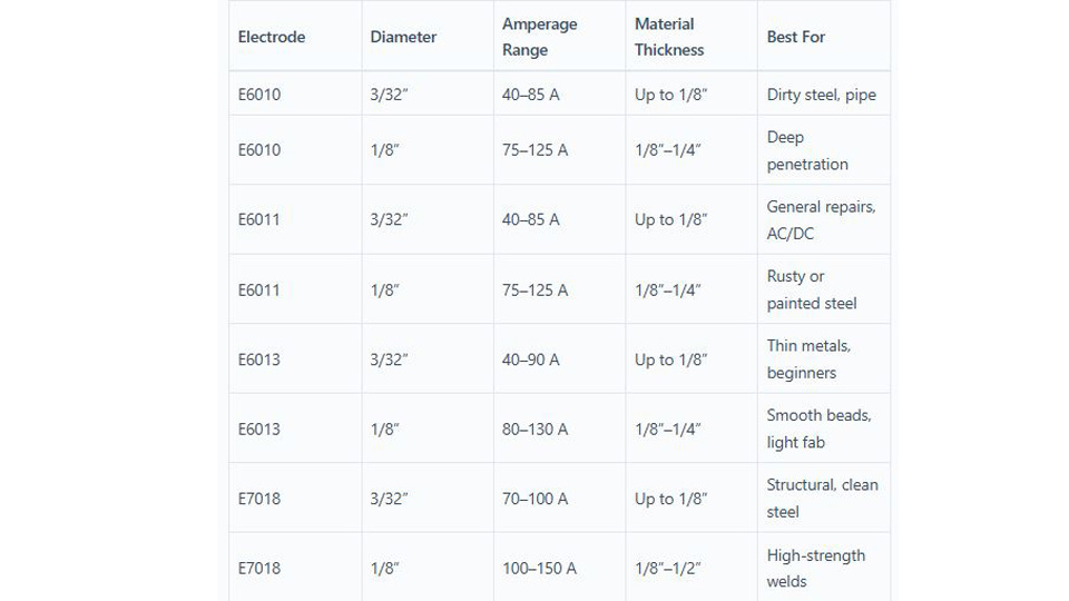
The following ranges are practical manufacturer-based examples, not universal AWS current limits. They draw from current product information for Lincoln Fleetweld E6010, Lincoln Fleetweld E6011, Lincoln Fleetweld E6013, Hobart E7018 guidance, and Lincoln E308L-16 data.
Note: Read the electrode container before welding. Two electrodes with the same AWS classification can have different recommended ranges, preferred polarities, exposure limits, or machine requirements.
| Electrode | Diameter | Typical Manufacturer Range | Common Current / Polarity | Typical Use |
|---|---|---|---|---|
| E6010 | 3/32 in (2.4 mm) | 50–85 A | DCEP | Open roots, pipe, forceful penetration |
| E6010 | 1/8 in (3.2 mm) | 75–135 A | DCEP | Roots, repairs, heavier material |
| E6010 | 5/32 in (4.0 mm) | 100–175 A | DCEP | Higher-deposition pipe and field work |
| E6011 | 3/32 in (2.4 mm) | 40–90 A | AC or approved DC polarity | Maintenance, repair, AC machines |
| E6011 | 1/8 in (3.2 mm) | 65–120 A | AC or approved DC polarity | General field and repair work |
| E6011 | 5/32 in (4.0 mm) | About 80–160 A | AC or approved DC polarity | Thicker repair and fabrication work |
| E6013 | 3/32 in (2.4 mm) | 70–115 A | AC, DCEP, or DCEN by product | Clean light steel, smooth beads |
| E6013 | 1/8 in (3.2 mm) | 100–140 A | AC, DCEP, or DCEN by product | General fabrication on clean steel |
| E6013 | 5/32 in (4.0 mm) | 145–200 A | AC, DCEP, or DCEN by product | Higher-deposition flat or horizontal work |
| E7018 | 3/32 in (2.4 mm) | 80–100 A | DCEP commonly preferred; AC or other polarity only when approved | Clean steel, low-hydrogen applications |
| E7018 | 1/8 in (3.2 mm) | 90–150 A | DCEP commonly preferred; AC or other polarity only when approved | Structural and multipass steel work |
| E7018 | 5/32 in (4.0 mm) | 110–230 A | DCEP commonly preferred; AC or other polarity only when approved | High-deposition, heavier multipass work |
| E308L-16 | 3/32 in (2.4 mm) | 40–70 A | DCEP or AC for cited product | Compatible 304-series stainless steel |
| E308L-16 | 1/8 in (3.2 mm) | 60–100 A | DCEP or AC for cited product | Compatible stainless fabrication |
| E308L-16 | 5/32 in (4.0 mm) | 90–140 A | DCEP or AC for cited product | Heavier compatible stainless work |
Products Worth Considering

ELECTRODE SPECIFICATION: E6013 welding rods with 3/32 inch diameter and 14-inch length, designed for general purpose arc welding applications on carbon steel materials

Package includes: you will receive 78 pieces of plastic welding rods in various colors, such as black, white, gray, transparent, etc., each color counting 12 pieces except for 6 pieces of transparent poly-carbonate rods, which are sufficient quantity and diverse varieties to meet your multiple demands

Model: The E6013 welding rods is a general-purpose mild steel electrode widely used with both AC and DC welding machines, and it's particularly well-suited for low-voltage AC welders.
Rod Size and Metal Thickness Guide
Base-metal thickness helps you choose a practical rod diameter, but it does not create a fixed maximum thickness for that rod. A properly prepared multipass joint can be welded with a smaller electrode than a single-pass chart might suggest.
| Approximate Steel Thickness | Practical Rod Starting Point | Important Notes |
|---|---|---|
| 18–16 gauge, about 0.048–0.060 in | 1/16- or 5/64-inch light-sheet electrode when specifically available | Stick is difficult here. Use tight fit-up, backing where suitable, short tacks, and plenty of cooling time. |
| 14–12 gauge, about 0.075–0.105 in | 5/64 or 3/32 inch | Begin near the low end of the exact product range and avoid a long arc. |
| 1/8–3/16 in | 3/32 or 1/8 inch | Joint fit-up, gap, position, and electrode penetration determine the better choice. |
| 1/4–3/8 in | 1/8 or 5/32 inch | Beveling and multiple passes are often required for full joint penetration. |
| Over 3/8 in | 1/8 or 5/32 inch in multiple passes | Use an engineered joint detail or approved WPS when strength or code compliance matters. |
Products Worth Considering

Use in all positions on low, medium and high-carbon steels

Product Introduction: E7018 welding rod is suitable for both AC and DC applications and can be used for all position welding

Diameter 1/16-Inch
How to Read and Use the Amperage Chart
- Identify the base metal. Confirm whether it is mild steel, stainless steel, cast iron, high-strength steel, or another alloy. Do not identify unknown metal by appearance alone when failure or fume exposure matters.
- Select the correct electrode classification. Match the rod to the base-metal grade, required weld properties, position, and service conditions.
- Check the rod diameter. The electrode diameter establishes the broad usable current range. Larger rods normally need more current.
- Read the electrode package. Confirm amperage, approved current type, polarity, positions, storage requirements, and any special restrictions.
- Check the machine. Verify that the welder can provide the required output, polarity, duty cycle, and electrode compatibility.
- Start near the middle of the range. Move lower for thin edges, large gaps, overhead work, or a small heat sink. Move higher for a large heat sink, some flat-position welds, or an arc that remains cold after the other variables are correct.
- Run a test bead on matching scrap. Use the same joint type, thickness, position, polarity, and surface condition whenever possible.
- Adjust in 5- to 10-amp steps. Change one variable at a time so you know what improved or harmed the bead.
- Inspect the result. Look for a stable arc, proper bead width, filled toes, manageable slag, no undercut, and evidence of fusion appropriate to the joint.
A useful starting rule is about 1 amp for every 0.001 inch of electrode diameter. A 1/8-inch rod is 0.125 inch, so 125 amps is a starting point—not a guaranteed final setting.
Miller’s stick-welding guidance recommends adjusting in small increments and accounting for the electrode, position, and finished bead. The range printed on your rod container still comes first.
Pro Tip: Keep a notebook or write settings on a clean piece of scrap. Record the rod brand, classification, diameter, polarity, position, material thickness, hot-start setting, arc-force setting, and final amperage. That record is far more useful than trying to remember one number for every job.
Choosing Amperage for Mild Steel
Mild steel is the most common material for DIY repair and general fabrication. E6011 and E6013 are common general-purpose choices, while E7018 is used where a compatible low-hydrogen deposit and higher weld-metal strength are required.
Use the lower portion of the approved range for thin edges or a joint with a large gap. Move upward only when the arc, bead, and fusion indicate more current is needed. Do not use extra amperage to compensate for paint, oil, bad fit-up, excessive arc length, or poor access.
Choosing Amperage for Stainless Steel
Select stainless filler by the actual base-metal grades and service conditions. E308L-16 commonly suits compatible 304-series stainless, while an E309L classification is often considered for certain stainless-to-carbon-steel joints. That does not make either rod universal.
For Lincoln Excalibur E308L-16, the listed operating range is 40–70 A for a 3/32-inch rod and 60–100 A for a 1/8-inch rod. Start inside the exact product range instead of applying one broad rule based only on stainless steel’s heat behavior.
Keep stainless tools separate from carbon-steel brushes and grinding dust where corrosion resistance matters. Stainless welding can also produce hexavalent chromium in the fume, so local exhaust and exposure controls deserve extra attention.
Choosing Amperage for Cast Iron
Cast iron is brittle and may crack because of its carbon content, casting condition, restraint, contamination, and rapid temperature changes. Nickel-based electrodes such as ENi-CI and nickel-iron products such as ENiFe-CI are common repair choices.
Use the electrode manufacturer’s amperage data, keep beads short, control interpass temperature, and allow the casting to cool slowly when the repair procedure calls for it. Light peening may help manage shrinkage stress on suitable repairs, but it must not damage or work-harden the bead.
E312 stainless electrodes are sometimes used for particular dissimilar-metal or difficult-to-weld joints, but E312 is not a nickel cast-iron classification and should not be presented as a direct replacement for ENi-CI or ENiFe-CI.
How Joint Design Changes the Best Setting
There is no dependable rule that every fillet weld needs a fixed percentage more amperage than every butt weld. The electrode still has an approved operating range, while the joint changes how much metal must be melted and deposited.
Important variables include:
- Root opening and fit-up
- Bevel angle and root face
- Single-pass versus multipass welding
- Fillet size or groove depth
- Joint restraint and heat sink
- Backing bars or backing material
- Access to the joint
- Required penetration and weld profile
For thick material, I bevel the edges when the joint design calls for it and use several controlled passes instead of trying to force one oversized pass with excessive current. That approach worked better when I welded 1/2-inch plate for a trailer-hitch project using 1/8-inch E7018 near 120 amps. However, a safety-critical trailer component should still follow an engineered design, qualified procedure, and suitable inspection. For machine preparation, see my step-by-step Lincoln stick-welder setup.
How Welding Position Changes Amperage
Flat welding normally allows a more fluid puddle because gravity helps hold the metal in the joint. Overhead and some vertical welds often work better with less current, a smaller puddle, and a tighter arc.
A reduction of about 5–15% from a successful flat setting can be a useful test for overhead or vertical work, but it is not a universal requirement. The electrode classification, direction of travel, joint, procedure, and manufacturer data control.
I once tried a vertical weld with the same hot setting that worked flat. The puddle sagged and the toes washed out. Lowering the current helped, but shortening the arc and using the correct manipulation for the electrode made just as much difference.
Use a controlled whip-and-pause technique only with electrodes and procedures that call for it, such as many E6010 or E6011 applications. E7018 generally favors a tight arc with stringer beads or a limited weave rather than a long whip.
Polarity: DCEP, DCEN, and AC
Polarity describes how the electrode holder and work lead connect to a DC machine:
- DCEP, or electrode positive: The electrode holder connects to the positive terminal and the work lead connects to the negative terminal.
- DCEN, or electrode negative: The electrode holder connects to the negative terminal and the work lead connects to the positive terminal.
- AC: Current reverses direction repeatedly, so there is no fixed positive electrode for the full cycle.
Common starting guidance is:
- E6010: Normally DCEP.
- E6011: Commonly AC or DCEP; check the exact product for any permitted DCEN use.
- E6013: Many products operate on AC, DCEP, or DCEN, but their recommended amperage can change with polarity.
- E7018: DCEP is commonly preferred. AC and other approved current arrangements depend on the exact product and machine.
- E308L-16: The cited Lincoln product lists DCEP and AC.
Do not assume that every modern welder provides both AC and DC. Many compact inverters are DC-only, while older transformer machines may be AC-only. Read the machine nameplate and manual before buying electrodes.
Hot Start, Arc Force, and Machine Output
Two welders set to the same displayed amperage can feel different because of their output characteristics and control settings.
Hot start briefly raises current when the arc is struck. It helps prevent sticking, but an excessive setting can gouge thin material or create a violent start.
Arc force, sometimes called dig, increases current when arc voltage drops. More arc force can keep a cellulosic electrode from extinguishing during a tight arc, but too much can increase spatter and make a smooth-running rod feel harsh.
Open-circuit voltage affects how readily some electrodes start and maintain an arc. A small inverter may have enough maximum amperage on paper yet still struggle with an electrode that requires different arc characteristics.
Duty cycle tells you how long the machine can weld at a stated output during a specified test period before it must cool. Check the machine manual before running a large electrode near maximum output for extended periods.
When an electrode keeps sticking, do not immediately add 30 amps. First confirm the rod size, polarity, work connection, hot start, arc force, machine compatibility, and electrode condition.
Setting Up Your Stick Welder
- Inspect the welder. Check the electrode holder, work lead, connectors, insulation, input cable, and machine case. Remove damaged equipment from service.
- Confirm the electrode. Read its classification, diameter, approved polarity, amperage range, position, and storage requirements.
- Prepare the joint. Remove oil, moisture, loose rust, paint, plating, and other contaminants as required. Identify hazardous coatings before grinding or welding them.
- Attach the work clamp. Place it on clean, bare metal with a solid electrical path close to the weld when practical.
- Select polarity. Connect the electrode holder and work lead as the electrode and machine instructions require.
- Set hot start and arc force. Begin near the machine’s neutral or recommended setting unless the manual or procedure gives a specific value.
- Set initial amperage. Start near the middle of the rod manufacturer’s range, then account for thickness, fit-up, and position.
- Strike the arc. Tap or scratch as appropriate, then establish a controlled arc. A useful starting arc length is near the electrode core diameter, but E7018 generally needs an especially tight arc.
- Run a test bead. Adjust by 5–10 amps at a time while keeping other variables as consistent as possible.
- Clean and inspect. Remove all slag before evaluating the bead or placing another pass.
What many welders call the “ground clamp” is more accurately the work clamp. It completes the welding circuit. It is not automatically the same thing as the welder’s protective equipment grounding, which must follow the machine manual and electrical requirements.
Common Amperage Problems and Fixes
| Symptom | Possible Causes | What to Check |
|---|---|---|
| Electrode sticks at the start | Low current, weak work connection, low hot start, oversized rod, poor striking technique, unsuitable machine, damaged coating | Clean and move the work clamp, confirm polarity, raise hot start or current slightly, and verify electrode compatibility |
| Tall, narrow bead | Current too low, travel too fast, poor joint access, or poor fusion | Raise current in a small step, slow travel slightly, maintain arc length, and inspect the joint faces |
| Wide, flat bead or undercut | Current too high, arc too long, travel too slow, excessive manipulation | Lower current, tighten the arc, correct travel speed, and reduce weave width |
| Burn-through | Too much heat for the edge thickness, large gap, slow travel, rod too large | Use a smaller rod, reduce current, improve fit-up, add backing where suitable, or use short intermittent welds |
| Excessive spatter | Long arc, excess current, excess arc force, wrong polarity, contamination | Shorten the arc, lower current or dig, confirm polarity, and clean the joint |
| Slag inclusions | Poor cleaning, low current, wrong angle, narrow groove, excessive weaving | Remove all slag, correct angle and bead placement, and ensure the joint provides access to both toes |
| Porosity | Moisture, oil, paint, rust, long arc, damaged electrode coating | Clean and dry the joint, use sound electrodes, tighten the arc, and follow storage instructions |
| Arc pulls to one side | Magnetic arc blow, especially with DC; current path or joint geometry | Move the work clamp, shorten the arc, reduce current, change weld sequence or direction, or use AC if the electrode and procedure permit it |
Storing and Redrying E7018 Electrodes
Low-hydrogen electrodes require more control than E6010, E6011, or E6013. Once a sealed container is opened, code work may impose a limited atmospheric-exposure period followed by heated storage.
Manufacturers commonly specify heated storage for opened E7018 electrodes, but reconditioning temperatures and times vary by product, strength level, moisture exposure, and coating condition. Do not treat 600°F for one hour as a universal recipe.
Follow the exact electrode manufacturer’s storage and redrying schedule. Use a dedicated electrode oven capable of holding the required temperature. Do not use food-preparation equipment for welding consumables.
Discard electrodes with cracked, flaking, contaminated, or otherwise damaged coatings. Redrying cannot repair physical coating damage or rusted core wire.
I once had E7018 electrodes that had sat in an unheated garage and became difficult to run consistently. Moisture was one possible factor, but so were cold material, starts, and machine settings. Following the product’s storage instructions and checking the rest of the setup was a better response than assuming every sticking rod needed the same rebake cycle.
Stick Welding Thin Metal Under 1/8 Inch
Stick welding sheet metal is possible, but MIG or TIG is often easier when appearance and heat control matter. Use the smallest suitable electrode listed for your machine and application.
A 1/16- or 5/64-inch light-sheet electrode may operate at relatively low current, but its exact range must come from the package. A 3/32-inch E6013 should not automatically be set to 20–50 amps; common manufacturer data begins much higher.
For thin steel:
- Use tight fit-up and remove gaps where possible.
- Use a backing bar when suitable for the joint.
- Keep a short arc.
- Use brief tacks or short stitch welds rather than one long pass.
- Move around the joint and allow cooling time.
- Avoid excessive weaving or repeatedly reheating the same edge.
Test on scrap of the same gauge before touching the actual part. My detailed process for controlling heat is in this guide to stick welding thin sheet without burn-through.
Stick Welding Thick Metal Over 1/4 Inch
Thick plate normally needs proper joint preparation and multiple passes. A 1/8-inch E7018 commonly operates around 90–150 amps, while a 5/32-inch E7018 may require roughly 110–230 amps depending on the product.
Bevel the edges when the joint design requires it, establish the root, remove all slag, and place fill and cap passes without exceeding required interpass temperatures. The goal is not simply to turn the machine up; it is to deposit the required weld metal with fusion and controlled heat input.
That multipass approach worked when I repaired a cracked backhoe bucket, but wear parts and heavily loaded equipment should be checked for base-metal grade, previous repairs, crack extent, and required preheat before welding.
Welding Dirty, Rusty, Painted, or Plated Metal
E6010 and E6011 tolerate mill scale, rust, and imperfect field conditions better than many smooth-running or low-hydrogen electrodes. That does not mean paint, oil, plating, or heavy rust should be left in the joint.
Clean to sound metal wherever practical. Unknown paint may contain lead, chromium, or other hazardous compounds. Galvanized coatings generate zinc-containing fume when heated. Identify the coating, remove it by an appropriate controlled method, and use suitable ventilation and respiratory protection based on the hazard assessment.
Do not automatically move a 3/32-inch E6010 or E6011 to 80–100 amps just because the steel is dirty. Stay inside the exact electrode range and solve contamination through preparation rather than excess current.
Vertical and Overhead Stick Welding
Start with a setting that works on matching scrap, then try a modest reduction if the puddle is too fluid. A smaller electrode often gives better control than forcing a large rod to run unusually cold.
Keep the arc tight and use the manipulation recommended for the electrode. E6010 and E6011 often use a controlled whip-and-pause movement. E7018 normally uses stringers or a limited weave with deliberate pauses at the toes.
I practiced vertical beads on scrap for weeks before attempting an overhead frame repair. That practice improved my consistency, but overhead or structural repairs still demand proper PPE, access, procedure selection, and inspection—not just muscle memory.
Stick Welding Safety
Wear a properly selected welding helmet, safety glasses, leather gloves, hearing protection where needed, boots, and flame-resistant clothing that covers exposed skin. Ordinary cotton is preferable to melting synthetic fabric, but a worn cotton shirt is not a substitute for rated flame-resistant welding clothing.
Inspect electrode holders, work leads, connectors, and insulation before use. I once saw damaged cable insulation begin sparking against nearby metal. That was a reminder that a damaged lead can cause shock, burns, short circuits, or fire and should be removed from service instead of wrapped up and ignored.
OSHA’s welding-fume guidance recommends controlling fumes at their source, positioning the welder away from the plume, and using local exhaust where needed. Outdoor welding does not automatically guarantee adequate ventilation.
Stainless-steel welding can generate hexavalent-chromium fume. Heating galvanized metal can produce zinc-oxide fume associated with metal fume fever. Stop work, move to fresh air, and seek medical attention when fume exposure causes breathing difficulty, chest tightness, severe irritation, dizziness, nausea, or other significant symptoms.
Keep suitable fire-extinguishing equipment ready. Remove combustibles from the hot-work area or shield them properly. OSHA’s general-industry hot-work rule identifies conditions involving combustible material within 35 feet that may require a trained fire watch, and the fire watch may need to continue after welding is finished.
Warning: Never weld, cut, or heat an unknown drum, tank, pipe, wheel, pressure vessel, or container that may have held fuel, solvent, gas, dust, or another hazardous substance. Do not weld in wet conditions, explosive atmospheres, or confined spaces without the required procedures, ventilation, testing, attendants, and rescue provisions.
Pros and Cons of Stick Welding
Pros:
- Versatile: Suitable electrodes can handle outdoor work, repairs, multiple positions, and less-than-perfect field conditions.
- Portable: The process does not require an external shielding-gas cylinder.
- Accessible: Basic machines and common steel electrodes are widely available.
- Capable on thick material: Proper joint preparation and multipass techniques can produce substantial welds.
- All-position options: Electrodes such as E6010, E6011, and E7018 are available for all-position work within their qualified procedures.
Cons:
- Slower cleanup: Rod changes and slag removal reduce productivity compared with some wire processes.
- Difficult on thin sheet: Heat input and electrode size make burn-through easier.
- Technique-sensitive: Arc starting, arc length, rod angle, and puddle control require practice.
- Fume and spatter: Covered electrodes generate slag, fume, and spatter that must be controlled.
- Consumable handling: Low-hydrogen rods may require heated storage and strict exposure control.
Conclusion
A stick welding amperage chart gives you a starting point, not a finished welding procedure. Begin with the range printed on the exact electrode, confirm polarity and machine compatibility, test on matching scrap, and tune the current in 5- to 10-amp steps.
The best setting is the one that produces a stable arc, controllable puddle, sound fusion, acceptable bead shape, and compliance with the job’s procedure. Good preparation, arc length, rod angle, travel speed, storage, ventilation, and inspection matter just as much as the number displayed on the machine.
For practice, repairs, and general fabrication, these steps remove much of the guesswork. For structural or life-safety work, use qualified procedures, suitable inspection, and a welder whose training matches the job.
Frequently Asked Questions
What is the best stick welding rod for beginners?
E6013 is often an approachable practice rod because it has a smooth arc and is available for common AC and DC machines. A 3/32-inch E6013 may run around 70–115 amps for the cited Lincoln product, but the package range controls. Practice on clean scrap and remove all slag before judging the bead.
How do I know whether stick welding amperage is too high or too low?
Low current may cause sticking, an unstable arc, or a tall bead with poor toe fusion. Excess current can create a harsh arc, wide flat bead, undercut, spatter, distortion, or burn-through. Arc length and travel speed can create similar symptoms, so change only one setting at a time.
Can I use the same amperage for every welding position?
Not always. Overhead and some vertical welds often benefit from roughly 5–15% less current than a successful flat setting, but the correct change depends on the electrode, direction, joint, and procedure. Test on scrap in the actual position rather than applying one automatic reduction.
How do I keep the electrode from sticking?
Confirm the rod diameter, amperage range, polarity, work-clamp connection, machine compatibility, hot-start setting, and striking technique. Raise current or hot start only in small steps. Replace damaged electrodes, and handle low-hydrogen rods according to the manufacturer’s storage and reconditioning instructions.
What is the difference between AC and DC stick welding?
AC reverses current direction repeatedly. DC keeps one direction and can be connected as DCEP or DCEN. E6010 is normally used on DCEP, E6011 commonly works on AC or DCEP, and many E6013 products allow several current choices. E7018 compatibility depends on the exact electrode and power source.
How many amps should I use for a 1/8-inch E7018 rod?
A common manufacturer range is about 90–150 amps. Around 120–125 amps is a practical test setting for many flat-position jobs, but thickness, joint design, position, polarity, machine behavior, and the exact electrode data may move the final setting.
Why does my welder behave differently from the amperage chart?
The display does not show every variable. Hot start, arc force, open-circuit voltage, duty cycle, input voltage, lead condition, polarity, electrode brand, and arc length all change how the arc feels. Confirm those items before assuming the chart is wrong or making a large current change.
Sources
- Miller Electric — Five Steps to Improving Your Stick Welding Technique — amperage starting rules, position adjustment, arc length, and 5- to 10-amp tuning.
- Lincoln Electric — Stick Electrode Guide — electrode classifications, diameters, polarity, and typical operating procedures.
- Hobart Brothers — 7018 Welding Rod Amperage — E7018 classification, current options, technique, and amperage ranges.
- Lincoln Electric — Excalibur 308L-16 — stainless-steel electrode applications, polarity, and operating ranges.
- Lincoln Electric — Storing and Redrying Electrodes — low-hydrogen electrode storage and reconditioning guidance.
- OSHA — Controlling Hazardous Fume and Gases During Welding — ventilation, coating, stainless-steel, fume, and respiratory hazards.