
Setting up a Lincoln stick welder correctly means more than choosing an amperage and striking an arc. You need to confirm the machine’s input power, inspect the leads, choose an electrode that matches the metal and current type, set polarity, attach the work clamp to clean metal, and test the settings on scrap before welding the actual joint.
Quick Answer
To set up a Lincoln stick welder, read the model nameplate and manual, connect it to the correct circuit, inspect the holder, work lead, and cables, choose the proper electrode, set AC or DC polarity, select a starting amperage from the rod package, clamp to clean metal, and run a test bead on scrap.
Key Takeaways
- Use the exact Lincoln manual and nameplate for input voltage, circuit requirements, output range, and duty cycle.
- Turn the welder off before connecting or changing output leads, polarity, or electrode setup.
- Match the rod classification, diameter, polarity, and amperage to the job and the machine.
- Attach the work clamp close to the weld on clean bare metal. The work lead is part of the welding circuit, not a substitute for equipment grounding.
- Practice on scrap, watch the arc and puddle, then adjust in small steps instead of guessing on the finished part.
At a Glance
| Time Required | About 20 to 30 minutes for inspection, setup, and a scrap-metal test |
| Difficulty | Beginner to intermediate, with electrical installation left to a qualified person |
| Tools Needed | Helmet, safety glasses, dry welding gloves, flame-resistant clothing, electrode, wire brush, chipping hammer, pliers, and scrap steel |
| Cost | No separate setup fee if you already own the machine and PPE; electrodes and worn safety gear are consumables |
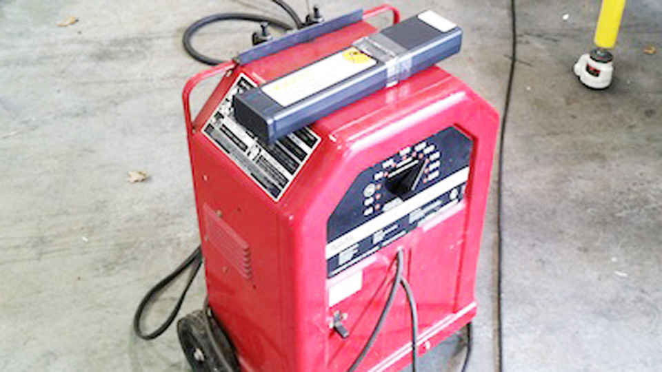
Image by weldingtipsandtricks
Affiliate disclosure: This article contains affiliate links. If you buy through one of these links, the site may earn a commission at no extra cost to you.
Why Proper Setup Matters for Stick Welding
Shielded metal arc welding, or SMAW, is useful for repairs, outdoor work, and many fabrication jobs because the electrode coating provides shielding without a separate gas cylinder. Some electrodes can tolerate light rust or mill scale better than typical solid-wire MIG, but that does not make surface preparation optional. Clean metal, correct fit-up, and the right rod still produce a more stable arc and a more reliable weld.
A poor setup can cause sticking, unstable arc starts, heavy spatter, porosity, undercut, lack of fusion, nuisance breaker trips, overheated cables, or damage to a selector switch. It can also expose you and nearby people to electric shock, arc radiation, hot slag, fire, and welding fumes.
Warning: Do not use a practice article as the only basis for welding structural beams, pressure vessels, lifting points, vehicle suspension or towing parts, fuel containers, or other safety-critical components. Those jobs may require a qualified welder, an approved welding procedure, code compliance, and formal inspection.
Understanding Your Lincoln Stick Welder
Before touching the controls, identify the exact model and code number on the nameplate. Lincoln uses different input voltages, output ranges, connector styles, and controls across transformer, inverter, and multi-process machines. Download the matching operator manual from the Lincoln Electric operator-manual library and follow that manual when it differs from general advice.
Common Lincoln Models for Stick Welding
| Model | What the Documentation Shows | Setup Point to Check |
|---|---|---|
| Invertec V155-S | Portable DC stick and DC TIG inverter with 120/230V auto-reconnect operation and a 5 to 155A DC output range. | Confirm the input plug, available circuit, electrode mode, and output limit. |
| AC/DC 225/125 | A 230V single-phase transformer machine with AC and DC stick output. Model literature lists up to 225A AC and 125A DC. | Use the correct 230V branch circuit and set both the output range and AC/DC selector as directed. |
| Idealarc 250 | A heavy constant-current AC/DC power source. Its manual lists up to 300A AC and 250A DC, depending on frequency and duty cycle. | Check installation, grounding, cable size, duty cycle, and the warning not to change polarity while welding. |
| Lincoln multi-process units | Some current stick welder, POWER MIG, MIG-PAK, and WELD-PAK models include SMAW, while others are wire-feed only. | Never assume a product family supports stick. Verify the exact model’s process list and required accessories. |
What to Verify on Any Lincoln Model
- Input power: Check voltage, phase, frequency, plug, breaker or fuse, and conductor requirements. A 120/230V inverter does not have the same supply needs as a 230V transformer machine.
- Output type: Confirm whether the machine supplies AC, DC, or both. A DC-only inverter cannot run an electrode that requires AC operation.
- Output connections: Some machines use detachable connectors. Others use fixed leads or a front-panel selector. Follow the diagram on the machine and in the manual.
- Duty cycle: This rating tells you how long the machine can weld at a stated output during a 10-minute period. For example, a 20% duty cycle means two minutes of welding followed by eight minutes of cooling at that rated output.
- Extra controls: Inverter models may include hot start, arc force, or soft and crisp electrode modes. Begin with the manufacturer’s recommended mode rather than turning every control to maximum.
Note: The work clamp is often called a “ground clamp,” but its main job is to complete the welding output circuit. The protective grounding conductor in the input cord or equipment grounding connection serves a different safety function.
Step-by-Step Guide to Setting Up Your Lincoln Stick Welder
The following sequence works for many Lincoln stick machines, but the model manual controls. Keep the welder switched off while inspecting the equipment and making output connections.
Products Worth Considering

Sold Individually: This product is sold as a single unit

Durable Material: ARCCAPTAIN electrode holder is made of high quality copper as well as insulating materials to ensure high efficiency and safety while welding.

Material: This STARTECHWELD electrode holder A-532 is made from copper alloy for maximum conductivity and strength. It has a comfortable insulated handle and is easy to operate.
Step 1: Read the Nameplate and Confirm Input Power
Find the model, code number, input voltage, rated input current, output range, and duty-cycle information. Make sure the available supply matches the machine. Do not force a plug into the wrong receptacle, use an improvised adapter, or replace a breaker with a larger one to stop trips.
Many 230V welders require a dedicated branch circuit. If the receptacle, plug, hardwiring, breaker, or conductor size is uncertain, have a qualified electrician install or verify it according to the manual and local electrical rules. Use an extension cord only when the manufacturer permits it, and choose the required conductor size for the full cord length.
Warning: Electric shock can be fatal. Keep gloves, clothing, the floor, and the work area dry. Do not weld in rain, standing water, or damp confined areas, and do not touch an energized electrode with bare skin.
Step 2: Gather Your Tools and Materials
Collect everything before energizing the machine:
- A compatible Lincoln stick welder connected to the correct supply.
- An intact electrode holder, work clamp, and correctly sized leads.
- Dry welding electrodes that match the base metal and output type.
- A welding helmet with the correct shade, safety glasses with side protection, dry welding gloves, flame-resistant clothing, leather footwear, and hearing protection when needed.
- A wire brush, chipping hammer, pliers, grinder as needed, and scrap metal for testing.
- A stable, noncombustible work surface such as a suitable welding table.
- A suitable fire extinguisher for the hazards in the area and a fire watch when sparks can reach hidden or nearby combustibles.
Step 3: Prepare a Safe Workspace
- Remove combustibles: Clear paper, cardboard, sawdust, fuel, aerosols, paint, oily rags, and other flammable items from the spark path. Check the other side of walls, floors, and panels.
- Control fumes: Keep your head out of the plume and use adequate natural ventilation, local exhaust, or both. Do not treat a respirator as a substitute for needed ventilation.
- Protect other people: Use nonflammable welding screens and prevent bystanders from viewing the arc.
- Secure the work: Clamp the pieces so they cannot shift as they heat and shrink.
- Avoid unknown coatings: Identify and safely remove paint, plating, oil, and chemical residue before welding. Galvanized, stainless, lead-painted, cadmium-coated, and solvent-contaminated materials need specific fume controls.
Do not weld on tanks, drums, pipes, or containers that held fuel or other combustible material unless a qualified procedure has made them safe. Never use oxygen for ventilation.
Step 4: Inspect the Welder, Holder, Clamp, and Leads
With input power off, inspect the power cord, plug, case, electrode holder, work clamp, connectors, and output cables. Look for exposed conductor, cracked insulation, loose lugs, burned jaws, weak clamp springs, or signs of overheating. Replace damaged parts before welding.
Route the leads so they do not cross walkways, sharp edges, hot metal, or moving equipment. Uncoil tightly bundled leads enough to prevent excess heat. Keep the holder dry and place it on an insulated surface when it is not in your hand.
Step 5: Choose the Right Electrode
The electrode classification tells you about strength, welding position, coating, and usable current. The table below covers common mild-steel rods, but the package and the Lincoln manual remain the final references.
| Electrode | Typical Use | Usual Current | Setup Notes |
|---|---|---|---|
| E6010 | Root passes, open joints, and maintenance work where a forceful, deep-penetrating arc is needed | DCEP (DC+) | Requires a compatible DC machine and controlled whip-and-pause technique; not every small inverter runs cellulosic rods well |
| E6011 | Repair work and steel with light surface contamination after reasonable cleaning | AC or DCEP | Fast-freeze slag and a forceful arc; useful on AC machines and for out-of-position work |
| E6013 | Clean mild steel, sheet, light fabrication, and jobs where smooth bead appearance matters | AC, DCEP, or DCEN, depending on the product | Soft arc and relatively shallow penetration; small diameters can help on thin metal |
| E7018 | Clean carbon steel and many structural applications that call for a low-hydrogen electrode | Usually DCEP or AC | Keep a short arc and store opened low-hydrogen electrodes as the manufacturer and applicable code require |
A 6011 electrode can be useful for repair work, but “runs on dirty steel” should not be treated as permission to weld over oil, heavy rust, paint, or moisture. A 7018 electrode gives a smoother low-hydrogen deposit when it is used on properly prepared steel and stored correctly.
Pro Tip: Buy rod diameters your machine can run comfortably at the available input power. A large electrode may fall within the machine’s maximum output but still exceed the practical duty cycle or circuit capacity for your setup.
Step 6: Connect the Output Leads and Set Polarity
Switch the welder off before making or changing connections. If your machine has detachable output connectors, seat and lock them fully. If it has fixed leads and a selector switch, use the selector exactly as the manual shows.
- DCEP or DC+: The electrode holder connects to positive and the work lead connects to negative.
- DCEN or DC-: The electrode holder connects to negative and the work lead connects to positive.
- AC: Current alternates, so there is no fixed positive or negative electrode polarity.
Attach the work clamp directly to clean bare metal on the workpiece, or to a metal table that has a reliable electrical path to the work. Put it close to the weld when practical. Remove paint, rust, and scale under the clamp jaws.
Warning: Do not change an AC/DC or polarity selector while the arc is on. Lincoln manuals for selector-equipped machines warn that switching under load can seriously damage the selector.
Step 7: Set a Starting Amperage and Machine Controls
Use the electrode package or product data sheet first. The ranges below are examples from Lincoln operating data for common rod sizes. They are starting ranges, not universal settings. Welding position, joint design, input voltage, arc length, and the exact electrode product can change the best setting.
| Electrode and Size | Polarity | Lincoln Example Range | Starting Approach |
|---|---|---|---|
| 3/32 in E6011 | AC / DCEP | 50 to 85A AC / 40 to 75A DCEP | Start near the middle, then raise current if the rod repeatedly sticks with a short arc |
| 1/8 in E6011 | AC / DCEP | 75 to 120A AC / 70 to 110A DCEP | Use the lower part of the range for out-of-position work or thinner material |
| 3/32 in E6013 | AC / DC | 50 to 80A AC / 45 to 75A DC | Useful for practice and lighter work when the machine has stable low-current output |
| 1/8 in E6013 | AC / DC | 75 to 105A AC / 70 to 95A DC | Watch for a fluid slag layer that can run ahead of the puddle |
| 3/32 in E7018 or E7018-1 | DCEP / AC | 70 to 110A DCEP / 80 to 120A AC | Keep a short arc and use a steady drag or slight manipulation |
| 1/8 in E7018 or E7018-1 | DCEP / AC | 90 to 160A DCEP / 100 to 160A AC | Begin near the middle of the product range and reduce current for vertical or overhead work |
For an inverter with hot start or arc force, begin at the default or manufacturer-recommended value. Too much arc force can increase spatter and make the puddle harder to control. Too little can make the rod feel soft or prone to sticking.
Step 8: Prepare and Fit the Joint
- Clean the weld zone: Remove oil, moisture, paint, plating, heavy rust, and loose scale from both sides of the joint where possible.
- Choose the joint design: Lap, tee, corner, and butt joints need different fit-up. Do not apply one gap or bevel to every job.
- Bevel thick material when required: Groove angle, root face, root opening, preheat, and pass sequence should follow an approved procedure for critical work.
- Tack securely: Place enough tacks to hold alignment and control distortion. Clean cracked or contaminated tacks before welding over them.
For thin sheet, stick welding is possible but less forgiving than MIG or TIG. Use a small electrode, stable low amperage, short welds or tacks, and a backing bar when suitable. Practice on scrap of the same thickness before touching the finished panel.
Step 9: Run a Test Bead, Strike the Arc, and Weld
Clamp a scrap piece of the same material and similar thickness. Put on all PPE, turn on the machine, and select the planned output. Insert the rod securely in the holder without touching the bare metal end.
- Strike the arc: Use a light tap or short scratch, then lift only enough to establish the arc.
- Keep a short arc: A useful starting point is an arc length near the electrode core-wire diameter, then adjust for the specific rod.
- Use the right travel angle: Most stick electrodes are dragged with a small lead angle. E6010 and E6011 often use a controlled whip-and-pause motion. E7018 normally uses a short arc and steady travel rather than a long whip.
- Watch the puddle: Focus on the molten metal at the leading edge, not only on the bright arc or the slag.
- Clean every pass: Chip and brush all slag before restarting or adding another pass.
If the rod sticks repeatedly, first check the clamp connection, arc-start technique, polarity, and rod condition. Then increase amperage in small steps within the product’s range. If the puddle becomes uncontrollable, edges wash away, or the plate burns through, reduce heat input by lowering current, shortening weld time, or moving faster as appropriate.
Step 10: Shut Down, Inspect, and Store the Equipment
After the final pass, let the weld cool enough to inspect safely. Remove slag and look for a consistent profile, good tie-in at both toes, and no visible cracks, pinholes, severe undercut, or trapped slag. A visual check cannot prove a safety-critical weld is acceptable, so required inspection must be performed by qualified personnel using the specified method.
Turn the output and power switch off, remove the electrode from the holder, and disconnect input power when the manual or work practice calls for it. Let the machine fan complete any normal cooling cycle before covering or storing the unit. Coil the leads loosely, keep the holder and clamp dry, and store electrodes by classification.
How to Store E6011, E6013, and E7018 Electrodes
Storage rules differ by coating type. Lincoln’s electrode-storage guidance says opened low-hydrogen cans should be held in a cabinet at 250 to 300°F (120 to 150°C). That holding temperature is not the same as a redrying cycle. Lincoln lists 650 to 750°F (340 to 400°C) for one hour as the final redrying temperature for exposed E7018 and E7028 electrodes, with pre-drying required after direct water contact or high humidity.
- E7018: Keep unopened containers sealed and store opened rods in a suitable holding oven when low-hydrogen control matters. Follow the rod label, project code, and manufacturer exposure limits.
- E6010 and E6011: Do not casually rebake fast-freeze electrodes. Lincoln states that rebaking this group is not recommended.
- E6013: Keep rods dry. If moisture affects performance, use only the manufacturer’s stated drying procedure because excess heat can damage the coating.
See Lincoln Electric’s storing and redrying guidance for the full temperature table.
Safety Considerations for Stick Welding
Eye and Face Protection
Use a welding helmet for every open-arc operation and wear safety glasses underneath it. OSHA’s general-industry shade guide lists shade 10 for SMAW with 1/16, 3/32, 1/8, and 5/32-inch electrodes; shade 12 for 3/16, 7/32, and 1/4-inch electrodes; and shade 14 for 5/16 and 3/8-inch electrodes. Choose a helmet that meets the applicable eye-protection standard and never look at an arc without proper protection.
Skin, Fire, and Hot-Metal Protection
Wear dry welding gloves, flame-resistant clothing that covers your skin, and high leather footwear without open cuffs that can catch slag. Remove lighters and other pressurized items from pockets. Treat recently welded metal, cutoffs, and electrode stubs as hot even when they no longer glow.
Fumes and Ventilation
Keep your head out of the fume plume and use enough ventilation or local exhaust to keep contaminants out of your breathing zone. If exposure cannot be controlled, stop and use a properly selected respiratory-protection approach. Respirator selection depends on the metal, coating, consumable, ventilation, and exposure assessment. Confined-space welding needs trained procedures, atmospheric controls, an attendant, and a rescue plan.
Electrical Safety
Inspect insulation, keep gloves and clothing dry, and avoid contact between your body and the work or ground. Do not place the holder where it can short against the table. Turn input power off before servicing the machine or opening covers. Only qualified personnel should work inside the welder.
A stable bead starts before the arc: correct power, sound cables, the right rod, clean metal, proper polarity, and a safe work area matter as much as hand technique.
Common Stick Welding Mistakes and Fixes
| Problem | Likely Causes | What to Check |
|---|---|---|
| Rod keeps sticking | Low current, long hesitation during starting, poor work connection, damp or damaged rod, or incorrect mode | Clean and move the clamp, shorten the strike, verify polarity, and raise current slightly within the rod range |
| Excessive spatter or harsh arc | Long arc, excessive current, wrong polarity, too much arc force, or contaminated metal | Shorten the arc, confirm polarity, reduce current or arc force, and clean the joint |
| Porosity | Oil, moisture, paint, damp low-hydrogen rod, long arc, or trapped contamination | Grind to clean metal, use correctly stored rods, maintain a short arc, and remove the defective weld before repair |
| Undercut | Excessive current, long arc, fast travel, or poor angle | Reduce current, shorten the arc, slow enough to fill the toes, and correct the travel angle |
| Lack of fusion or cold lap | Low heat, fast travel, poor joint access, slag ahead of the puddle, or insufficient cleaning | Improve joint prep, raise current within range, adjust angle and travel, and keep slag behind the puddle |
| Arc wanders or blows sideways | Magnetic arc blow, work-lead position, joint geometry, or DC current | Move the work clamp, shorten the arc, weld toward a tack, reduce current, or use AC when the rod and machine allow it |
| Breaker trips or thermal light comes on | Wrong supply, undersized extension cord, overloaded circuit, blocked airflow, or exceeded duty cycle | Stop welding, verify the circuit and cord against the manual, clear vents, and let the machine cool |
Choosing the Right Lincoln Stick Welder for Your Needs
Choose by capability rather than by brand family name alone. A useful buying checklist includes:
- Available input power: Decide whether you need 120V portability, 230V output, or dual-voltage flexibility.
- Required current type: DC gives a smoother arc for many rods, while AC can help reduce arc blow and supports electrodes made for AC.
- Output and duty cycle: Match realistic rod sizes and welding time, not only the maximum amperage printed in large type.
- Cellulosic-electrode performance: If you plan to run E6010, verify that the inverter is designed for it.
- Portability: A small inverter suits field repair and light fabrication. A large transformer machine suits a fixed shop with adequate electrical service.
- Process range: Buy a multi-process machine only when you will use MIG, flux-core, TIG, or stick functions and understand the accessories each process needs.
- Parts and service: Confirm local support, replacement leads, connectors, and current operator documentation for the exact model.
The AC/DC 225/125 remains a straightforward shop-style example, the Invertec V155-S shows the portability of a dual-voltage DC inverter, and the Idealarc 250 represents a high-output transformer machine. Current availability varies by region, so compare present specifications rather than relying on an old model name alone.
Products Worth Considering

Can handle 6011/6013/7018 electrode, adopting IGBT Inverter power system, suitable for mild steel, cast iron, stainless steel as well as hard surfacing.

More Powerful: Up to 205 amps with Hot Start & Arc Force,adopts IGBT Technology for more efficient and smoother arc quality. Weld continuously without interruption, significantly reducing the risk of welding rod sticking during the welding process. Compatible with most 6010, 6011, 6013 and 7018 welding rods,supports dual voltage (110V/220V). Ideal for welding stainless steel, mild steel, and other metal materials,delivering strong and durable weld joints
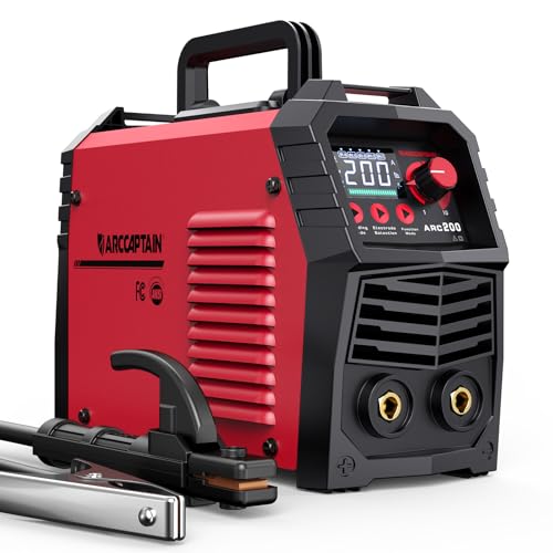
【EASY TO USE】Intelligent LED screen design, provides you with accurate data display and more choices, helps you read it easier and more clearly without taking off your helmet. Good performance on 6010, 6011, 6013 and 7018 rods. It's very suitable for outdoor maintenance, garage, farm, craft, and home DIY. Note: DO NOT power on until the screen turns off and the fan stops working!
Comparison of Stick Welding vs. Other Processes
| Process | Best Fit | Main Advantages | Main Limits |
|---|---|---|---|
| Stick (SMAW) | Outdoor repairs, maintenance, heavier steel, and jobs where carrying shielding gas is inconvenient | Simple equipment, wide electrode choice, good wind tolerance, and strong out-of-position capability with the right rod | Slag cleanup, more starts and stops, smoke, and a steeper learning curve on thin sheet |
| MIG (GMAW) | Clean indoor fabrication, auto work, and production where speed matters | Fast deposition, easy starts, little slag, and good thin-metal control | Shielding gas is wind-sensitive, surfaces must be cleaner, and wire-feed setup adds parts |
| Flux-Cored (FCAW) | Fabrication and field work, depending on whether the wire is gas-shielded or self-shielded | High deposition and easier continuous welding than stick | More fume and spatter than solid-wire MIG, plus slag on many wires |
| TIG (GTAW) | Thin material, stainless, aluminum with suitable AC equipment, and work where precise control matters | Clean, precise welds and excellent puddle control | Slow, sensitive to contamination, and requires more coordination and shielding equipment |
Conclusion
A safe Lincoln stick-welder setup follows a repeatable order: identify the exact machine, confirm the input circuit, inspect the equipment, prepare the work area, choose the right electrode, set polarity and amperage from reliable data, attach the work clamp to clean metal, and test on scrap. That process prevents many arc problems before they start.
Do not rush past the manual or safety checks. Small differences between Lincoln models can change the input requirement, connector arrangement, output type, and duty cycle. Once the setup is correct, practice short-arc control and puddle observation on noncritical scrap before moving to finished work.
Frequently Asked Questions
What is the best electrode for a Lincoln stick welder?
There is no single best rod. E6011 is useful for repair work and runs on AC or DCEP. E6013 gives a softer arc on clean mild steel and light fabrication. E7018 is a low-hydrogen choice for clean steel when the job, storage conditions, and procedure call for it. Match the rod to the base metal, position, current type, machine capability, and required weld properties.
How do I know what amperage to set on my Lincoln welder?
Start with the range printed on the electrode package or Lincoln product data. Choose a value near the middle, then test on scrap. Raise current slightly if the rod sticks despite good technique and a clean work connection. Lower it if the puddle is too fluid, the edges undercut, or thin metal burns through. Stay within the stated range.
Can I use a Lincoln stick welder on thin metal?
Yes, but it is less forgiving than MIG or TIG. Use a small electrode such as 3/32-inch E6013 when compatible, stable low current, a short arc, and short welds or tacks. A backing bar may help. Practice on scrap of the same gauge because machine response and joint design matter more than one universal amperage number.
Why does my electrode keep sticking?
Common causes include low current, a slow arc strike, a dirty or loose work connection, incorrect polarity, damp or damaged electrodes, and an unsuitable machine mode. Clean and reposition the clamp, verify polarity, use a quick controlled strike, and adjust current in small steps within the rod manufacturer’s range.
Is stick welding with a Lincoln welder safe for beginners?
A beginner can practice stick welding safely only after learning electrical, fire, fume, eye, skin, and hot-metal precautions. Use the correct circuit, dry PPE, a welding helmet and safety glasses, ventilation, a cleared work area, and noncritical scrap. Get hands-on instruction before welding structural or safety-critical parts.
What do DC+, DC-, and AC mean on a stick welder?
DC+ means direct-current electrode positive, also called DCEP. DC- means direct-current electrode negative, or DCEN. AC reverses direction repeatedly and has no fixed electrode polarity. Use the current and polarity listed for the exact electrode, and connect or select the output with the welder switched off.
Why does my welder trip the breaker or stop on thermal protection?
The machine may be on the wrong or undersized circuit, sharing a heavily loaded branch circuit, using an undersized extension cord, operating with blocked vents, or exceeding its duty cycle. Stop welding, let it cool, and compare the full electrical setup with the operator manual. Do not install a larger breaker as a shortcut.
Can I run a Lincoln stick welder from a generator or long extension cord?
Only when the exact Lincoln manual allows it and the generator or cord meets the stated requirements. Voltage regulation, generator output, conductor size, plug type, and total length all matter. An undersized cord can cause voltage drop, poor arc performance, overheating, or nuisance trips.
Sources
- Lincoln Electric AC/DC 225/125 product information: input type, AC/DC capability, and output range
- Lincoln Electric Invertec V155-S product information: 120/230V operation, DC processes, and output range
- Lincoln Electric Idealarc 250 operator manual: installation, polarity selector, output, duty cycle, and safety warnings
- Lincoln Electric: Storing and Redrying Electrodes: low-hydrogen holding temperatures and electrode redrying guidance
- Lincoln Electric Welding Wire and Electrode Safe Use Guide: ventilation, fume, fire, PPE, and respirator guidance
- OSHA 29 CFR 1910.252: arc-welding eye protection, shade guidance, screens, clothing, ventilation, and hot-work precautions



[…] A butt weld needs less amperage than a fillet weld, which requires about 10% more power for good fusion. For thick metals, I bevel the edges to create a V-groove, allowing better penetration with smaller rods and lower amps. This saved me when welding a 1/2” plate for a custom trailer hitch—multiple passes with a 1/8” E7018 at ~120 amps did the trick. For a model-specific walkthrough, see my step-by-step Lincoln stick setup. […]