I once had to size a pair of fillet welds on a T-joint made from plates of different thicknesses. The bead looked solid, but appearance alone could not tell me whether the weld, base metal, or connected part would carry the required load. The useful answer came from checking the effective throat, weld length, filler classification, load direction, and every other limit state in the connection.
This guide explains how to calculate fillet weld strength under AISC 360-22 using both LRFD and ASD. It also covers the current AWS D1.1/D1.1M:2025-AMD1 scope, weld-size limits, directional strength, long welds, eccentric loading, base-metal checks, fatigue, inspection, and shop safety.
Quick Answer
For an equal-leg fillet joining surfaces at 90°, calculate effective area as Awe = 0.707wLe. Under AISC 360-22, nominal weld strength is Rn = 0.60FEXXAwekds. Use φ = 0.75 for LRFD or Ω = 2.00 for ASD, then check weld-size, base-metal, fatigue, and connection limits.
Key Takeaways
- Fillet weld strength is based on the effective throat area, not the visible face width or convex reinforcement.
- The 0.707 factor applies to a standard equal-leg fillet between surfaces meeting at 90°.
- The AISC directional factor is kds = 1.0 + 0.50[sin(θ)]1.5, not sin(1.5θ).
- A weld-metal calculation is only one part of the connection check; the base metal, connected parts, load path, and fatigue can govern.
- Use the code edition, welding procedure specification, drawings, filler, and inspection criteria required by the project.
At a Glance
| Time Required | About 10–30 minutes for a simple concentric weld group; longer for eccentric, fatigue-sensitive, tubular, or multi-directional connections |
| Difficulty | Intermediate for a straight weld under concentric load; advanced for weld groups, fatigue, seismic, lifting, or fracture-critical work |
| Tools Needed | Calculator or spreadsheet, connection drawing, current governing code, filler classification, weld gauge, and the approved WPS |
| Cost | The arithmetic may cost nothing; code access, a weld gauge, qualified inspection, testing, or engineering review can add cost |
Warning: This guide is an educational calculation aid, not approval for a real connection. Structural, lifting, vehicle, overhead, seismic, bridge, fatigue-sensitive, pressure-containing, or public-safety work should be designed and reviewed by a qualified professional and welded under the governing drawings, code, WPS, and inspection plan. Never rate a connection from bead appearance alone.
What Is a Fillet Weld?
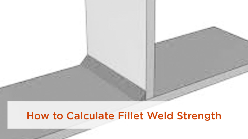
A fillet weld joins surfaces that meet or overlap, most often in a lap joint, T-joint, or corner joint. Its cross-section is roughly triangular, with one leg on each connected surface. Unlike a complete-joint-penetration groove weld, a normal fillet weld is designed from its effective throat rather than the full thickness of the parts.
The main geometric terms are:
- Leg size, w: The distance from the weld root to the toe along a connected surface.
- Weld face: The exposed surface of the completed weld.
- Root: The point where the connected surfaces meet behind the weld.
- Effective throat, te: The shortest effective distance from the root to the weld face, subject to the governing code and qualified detail.
- Effective length, Le: The length used to calculate the effective weld area.
For more detail on plate-edge limitations, see this guide to the maximum fillet weld size for plate thickness.
Common Fillet Weld Applications
Fillet welds appear in brackets, base plates, stiffeners, frames, machinery, trailer components, racks, structural connections, and many other assemblies. Their widespread use does not make every application interchangeable. A lightly loaded shop bracket, a vehicle suspension part, and a building connection can require different load assumptions, codes, procedures, inspections, and fatigue checks.
Which Code Applies to the Calculation?
For U.S. structural-steel buildings and similar structures, ANSI/AISC 360-22 provides generally applicable structural-steel design requirements and includes both LRFD and ASD. Section J2 addresses welded connections, including fillet-weld effective area, dimensional limits, and strength.
AWS D1.1/D1.1M:2025-AMD1 is the current Structural Welding Code—Steel for commonly used carbon and low-alloy constructional steels. It addresses welded-connection design provisions, procedure and personnel qualification, fabrication, workmanship, inspection, and acceptance requirements.
Note: The adopted building code, contract documents, engineer’s criteria, drawings, and referenced standards determine what governs. AISC and AWS provisions should not be mixed selectively to create a more favorable result.
This article’s main equations address the common AISC 360 structural-steel case. They are not universal for every material or industry:
- Structural stainless design may fall under AISC 370-25, while structural stainless welding is covered by AWS D1.6/D1.6M and project requirements.
- Bridges may be governed by AASHTO and AASHTO/AWS D1.5.
- Seismic-force-resisting systems may require AISC 341 and AWS D1.8 in addition to other project documents.
- Pressure vessels, piping, sheet steel, aluminum, reinforcing bars, railroads, and other applications have different governing standards.
Inputs You Need Before Calculating Fillet Weld Strength
Do not begin with the bead size alone. Gather the following information first:
- Required load: Use factored loads for LRFD or service-level loads combined under the applicable ASD provisions. Do not compare an LRFD capacity with an ASD demand.
- Load direction: Establish the angle between the force and the weld’s longitudinal axis.
- Weld layout: Record every weld segment, its orientation, actual length, location, and whether it is end-loaded.
- Joint geometry: Confirm whether the fillet is equal-leg or unequal-leg and whether the connected surfaces meet at 90°.
- Filler classification: Identify FEXX from the approved filler and WPS.
- Connected materials: Record plate thicknesses and specified base-metal strengths.
- Load path and eccentricity: Determine whether the load passes through the weld-group centroid or creates a moment.
- Service conditions: Identify cyclic loading, impact, temperature, corrosion, seismic demand, lifting service, or fracture-critical requirements.
- Fit-up and fabrication requirements: Check root opening, weld access, position, preheat, filler compatibility, and inspection requirements.
Fillet Weld Anatomy and Effective Throat
For an equal-leg fillet joining surfaces that meet at 90°, the theoretical effective throat is:
te = w cos 45° = 0.707w
The effective weld area is:
Awe = teLe = 0.707wLe
For two identical fillets, add the effective areas of both welds. The easiest method is often to use the total effective length of all applicable segments.
The 0.707 shortcut should not be used blindly for unequal-leg welds, skewed T-joints, or surfaces that do not meet at 90°. In those cases, determine the shortest effective distance from the root to the weld face using the actual qualified geometry and governing provisions.
Pro Tip: Keep the unrounded throat and area values in your calculator or spreadsheet. Round only the final reported capacity. Early rounding caused the original worked example to understate both ASD and LRFD strength slightly.
Why Convexity Does Not Automatically Add Design Strength
A convex weld face may contain more deposited metal, but ordinary convex reinforcement is not automatically added to the effective throat. Design from the effective throat recognized by the governing specification and qualified joint detail. Certain qualified processes or details may receive credit for penetration, but that is not the same as counting any visible reinforcement.
How Fit-Up and Joint Preparation Affect the Result
Joint preparation strongly affects whether the completed weld can develop the calculated capacity. Remove contaminants and coatings as required by the WPS, provide the specified root opening and access, and make sure the welding process can fuse both members.
Do not add an arbitrary toe chamfer, bevel, backing, or grinding operation simply because the material exceeds a certain thickness. Those changes can alter the joint detail, required procedure, inspection, and effective weld geometry. Follow the approved drawing and WPS. If a load-carrying weld is ground, verify that the remaining profile and size still satisfy the requirement.
The AISC Fillet Weld Strength Formula
AISC nominal fillet-weld strength: Rn = 0.60FEXXAwekds
The variables are:
| Symbol | Meaning |
|---|---|
| Rn | Nominal weld-metal strength |
| FEXX | Filler-metal classification strength, such as 70 ksi for an approved E70 or ER70 classification |
| Awe | Effective weld area, equal to effective throat multiplied by effective length |
| kds | Directional-strength factor, subject to AISC restrictions |
| φ | LRFD resistance factor; 0.75 for this weld-metal limit state |
| Ω | ASD safety factor; 2.00 for this weld-metal limit state |
LRFD Fillet Weld Strength
For LRFD:
φRn = 0.75(0.60FEXXAwekds)
For a longitudinally loaded fillet where kds = 1.0, the design stress on the effective area is:
0.75 × 0.60FEXX = 0.45FEXX
ASD Fillet Weld Strength
For ASD:
Rn/Ω = (0.60FEXXAwekds)/2.00
For a longitudinally loaded fillet where kds = 1.0, this becomes:
0.30FEXXAwe
Correct AISC Directional Strength Factor
The directional-strength factor is:
kds = 1.0 + 0.50[sin(θ)]1.5
Here, θ is the angle between the direction of force and the weld’s longitudinal axis:
- At θ = 0°, the load is parallel to the weld and kds = 1.0.
- At θ = 90°, the load is perpendicular to the weld and kds = 1.5.
- At intermediate angles, calculate the sine of θ first and then raise that result to the 1.5 power.
For example, at θ = 30°:
kds = 1.0 + 0.50(0.5)1.5 ≈ 1.177
Writing the formula as `sin(1.5θ)` would incorrectly give about 1.354 at 30°, materially overstating the weld strength.
Note: Do not apply a 1.5 multiplier automatically to an entire weld group. AISC requires strain compatibility when a group contains differently oriented weld elements, and the directional increase is prohibited for certain fillet welds subject to tension around the perimeter ends of square and rectangular HSS members. The instantaneous-center-of-rotation method is one recognized approach for applicable weld groups.
Step-by-Step Fillet Weld Strength Calculation
- Select LRFD or ASD. Use the same design format for both required strength and available strength.
- Confirm the weld is dimensionally permitted. Check minimum size, maximum edge size, minimum segment length, effective length, and any end-loaded long-weld reduction.
- Calculate effective throat and area. For a standard equal-leg 90° fillet, use te = 0.707w and Awe = teLe.
- Calculate weld-metal strength. Use Rn = 0.60FEXXAwekds, followed by φ for LRFD or Ω for ASD.
- Check the full connection. Verify the base metal, connected parts, weld group, eccentricity, fatigue, service conditions, and applicable detailing and inspection provisions.
Worked Example: Two 3/16-Inch Fillet Welds
Consider two 1/4-in A36 plates in a lap joint. The connection has two equal-leg fillet welds, each 6 in long, with a specified 3/16-in leg size. The approved filler has FEXX = 70 ksi. The load acts parallel to the weld axes, so kds = 1.0.
- Weld size: w = 3/16 in = 0.1875 in.
- Effective throat: te = 0.707 × 0.1875 = 0.13256 in.
- Total weld length: L = 2 × 6 = 12 in.
- Effective area: Awe = 0.13256 × 12 = 1.59075 in².
- Nominal strength: Rn = 0.60 × 70 × 1.59075 = 66.81 kips.
- LRFD strength: φRn = 0.75 × 66.81 = 50.1 kips.
- ASD strength: Rn/Ω = 66.81/2.00 = 33.4 kips.
The dimensional checks also matter:
- The AISC minimum size for a 1/4-in thinner connected part is 1/8 in, so a 3/16-in weld satisfies the minimum.
- Along the edge of a 1/4-in plate, the usual maximum is the plate thickness minus 1/16 in, which is 3/16 in. The proposed weld is at that limit.
- Each 6-in segment is much longer than four times the 3/16-in weld size.
- L/w for each 6-in weld is 32, so the end-loaded long-weld reduction would not apply even if the loading qualified as end loading.
If the force were perpendicular to both straight welds and the directional increase were permitted, the weld-metal LRFD value could be multiplied by 1.5, producing about 75.2 kips. That number would still not be the approved capacity of the complete connection until the connected parts, base metal, load distribution, and all other limit states were checked.
| Case | Available weld-metal strength | Key caution |
|---|---|---|
| Longitudinal load, θ = 0° | LRFD: 0.75(0.60FEXXAwe) ASD: 0.60FEXXAwe/2.00 |
Use the permitted effective area and check the connected material |
| Single eligible weld orientation at angle θ | Multiply nominal weld strength by 1.0 + 0.50[sin(θ)]1.5 | Apply AISC restrictions and do not confuse the exponent with sin(1.5θ) |
| Multi-directional or eccentric weld group | Analyze force and moment distribution using a recognized weld-group method | Strain compatibility and the critical weld element can govern |
| Fatigue-sensitive connection | Static weld strength is only one check | Use the governing stress range, detail category, loading cycles, and project requirements |
Minimum Fillet Weld Size
AISC Table J2.4 sets minimum fillet weld sizes based on the thickness of the thinner connected part. These minimums help provide adequate heat input and reduce the risk of rapid cooling in the thicker assembly. Project documents or another governing code may require more.
| Thickness of thinner part | Minimum fillet weld size |
|---|---|
| Up to and including 1/4 in | 1/8 in |
| Over 1/4 in through 1/2 in | 3/16 in |
| Over 1/2 in through 3/4 in | 1/4 in |
| Over 3/4 in through 1-1/2 in | 5/16 in |
| Over 1-1/2 in through 2-1/4 in | 3/8 in |
| Over 2-1/4 in through 6 in | 1/2 in |
| Over 6 in | 5/8 in |
These values do not prove that the minimum weld is strong enough. The required strength calculation may demand a larger weld, and the maximum permitted size can still limit the detail.
Maximum Fillet Weld Size Along Plate Edges
For fillet welds placed along an edge of connected material:
- If the connected part is less than 1/4 in thick, the maximum specified leg size is generally the part thickness.
- If the connected part is at least 1/4 in thick, the maximum specified leg size is generally the thickness minus 1/16 in unless the drawing specifically designates a full-size weld with suitable detailing.
The 1/16-in reduction helps preserve a visible plate edge so inspectors can verify the required weld leg instead of mistaking a melted edge for adequate weld size. This edge rule should not be applied indiscriminately to every interior T-joint.
Minimum Weld Length and Intermittent Fillet Welds
A strength-designed fillet weld segment should be at least four times its nominal weld size. If it is shorter, the effective weld size cannot be taken as greater than one-quarter of the segment length.
For example, a 1/4-in fillet intended to use the full 1/4-in size should have a segment at least 1 in long. A 3/4-in-long segment could not be credited with an effective size greater than 3/16 in under that rule.
Intermittent welds do not have a universal “75% efficiency.” Calculate their capacity from the actual qualifying effective length of the individual segments. Also check minimum segment length, spacing, sealing or corrosion needs, built-up-member rules, fatigue, and drawing requirements.
Long End-Loaded Fillet Welds
Long fillet welds loaded through their ends may not distribute force uniformly over their full actual length. For qualifying end-loaded fillets, AISC uses the following effective-length limits:
- L ≤ 100w: Le = L.
- 100w < L ≤ 300w: β = 1.2 − 0.002(L/w), with β ≤ 1.0, and Le = βL.
- L > 300w: Le = 180w.
Here, L is the actual length of the qualifying end-loaded weld and w is its leg size. Do not apply this reduction automatically to a transverse weld or to every weld that happens to be long. First determine whether the detail and force transfer meet the code’s end-loaded condition.
End Returns and Weld Terminations
There is no universal rule requiring every fillet weld to wrap around a corner for two weld sizes. Weld termination depends on the connection type, stress direction, required seal, corner geometry, fatigue behavior, and project detail.
Some details terminate the weld short of an edge; others require a return, a continuous weld, or a weld-all-around symbol. Blindly welding around an out-of-plane corner can create poor fit-up, notches, difficult access, or an unintended load path. Follow the drawing and applicable AISC and AWS termination provisions.
Load Direction, Eccentricity, and Weld Groups
The simple area-times-stress equation works most directly when a concentric force is distributed predictably through welds of one orientation. Many real connections are eccentric. A bracket, clip angle, seat, tab, or base-plate attachment can place the weld group under direct shear plus a moment.
For an eccentric in-plane load, the analysis commonly includes:
- Direct shear distributed through the weld group.
- Secondary shear caused by the moment about the weld-group centroid.
- Vector combination at the critical point in the weld group.
- An elastic weld-group method or the instantaneous-center-of-rotation method, as appropriate.
For out-of-plane forces, welds may experience combinations of shear, tension, and bending-related effects. A single total throat area multiplied by one allowable stress may miss the most highly loaded weld segment.
Base-Metal and Connected-Part Checks
The calculated weld-metal strength is not automatically the strength of the whole connection. Depending on the load path and geometry, check applicable limit states such as:
- Base-metal yielding.
- Shear rupture or tension rupture next to the weld.
- Block shear of the connected element.
- Local yielding, crippling, bending, or tear-out.
- Net-section rupture.
- HSS wall plastification, punching shear, sidewall yielding, or other tubular limit states.
- Buckling or prying action in the connected part.
- Anchor, bolt, plate, or supporting-member limits elsewhere in the load path.
AISC notes that a separate fusion-zone check along the weld leg generally does not govern when matching filler strength is used because the weld throat is more critical. That does not eliminate the need to check the connected material outside that local fusion-face comparison.
Filler Metal and Welding Process
Within the same applicable code model, the approved FEXX classification—not whether the arc came from MIG, stick, or TIG—sets the nominal filler-strength term. The process still matters because it affects deposition rate, access, position, penetration profile, heat input, defect control, procedure qualification, and the likelihood of achieving sound fusion.
| Filler example | Typical use | Design and shop considerations |
|---|---|---|
| E7018, SMAW | Common structural carbon and low-alloy steel applications | 70-ksi classification; low-hydrogen handling, exposure, holding, and redrying must follow the product data, WPS, and governing code |
| ER70S-6, GMAW/GTAW | Many carbon-steel fabrication applications | 70-ksi classification; shielding, transfer mode, position, joint access, and parameters must provide adequate fusion |
| ER308L and related stainless fillers | Selected stainless combinations | Compatibility depends on base-metal grade, service, corrosion, temperature, dilution, and the governing stainless welding requirements; 308L is not a universal stainless choice |
Products Worth Considering

MODEL: E7018 is a low-hydrogen iron powder type electrode that produces high quality x-ray welds. It can be used in all positions on AC or DC reverse polarity welding current.

E7018 Welding Rod: Diameter: 3/32''; Length: 14"; Weight: 5 lb.

E7018 Welding Rod: Diameter: 1/8"; Length: 14"; Weight: 10lb.
MIG, Stick, and TIG Fillet Weld Strength
MIG, stick, and TIG can use the same FEXX-based structural design framework when the material, filler, process, joint, and procedure are within the governing code’s scope. That does not mean they produce interchangeable results without qualification.
- GMAW/MIG: Productive and clean, but an attractive bead can still hide incomplete fusion when voltage, wire feed, travel speed, gun angle, transfer mode, or joint access is wrong.
- SMAW/stick: Flexible for field and positional work, but electrode storage, slag removal, arc length, and tie-in are important.
- GTAW/TIG: Precise and controllable, but normally slower and sensitive to cleanliness and operator technique.
Use an approved WPS and make test welds when required. Machine settings from a chart or online article are not a substitute for the procedure, filler data, qualification range, and actual joint conditions.
Inspection and Common Fillet Weld Problems
A weld gauge can check leg size, throat-related profile, convexity, concavity, and undercut, but visual measurement cannot prove internal fusion or complete code compliance.
Common problems include:
- Undersized legs: The effective area may be smaller than the design assumes.
- Excessive convexity: Extra face metal does not necessarily increase the effective throat and may create a poor transition.
- Excessive concavity: The actual throat may be inadequate.
- Undercut: A groove melted into the base metal can create a stress concentration and may exceed acceptance limits.
- Incomplete fusion: The deposited metal has not fused adequately to the base metal or previous weld pass.
- Porosity or inclusions: Acceptance depends on type, size, distribution, loading, and the governing inspection criteria.
- Excessive root opening: Fit-up can change the required weld size, procedure, or effective geometry.
- Cracks: Cracks are a serious discontinuity and require evaluation under the governing requirements.
Do not convert every visible discontinuity into an improvised percentage reduction in weld area. Apply the specified inspection method and acceptance criteria. Repairs should use an approved repair procedure rather than uncontrolled grinding and rewelding.
Products Worth Considering

7piece Fillet Weld Set Gage Rl Gauge

【7 pieces Weld Fillet Gauges】: 7 pieces weld fillet gauges are held by bolt and nut that can be disassembled, each weld gauge can be used to check the size of fillet legs and fillet throats

❤WELD GAUGE SET❤ Package Includes 1 x Undercuts Checking Gauge, 1 x Convexity Concavity Checking Gauge, 2 x Instructions, 2 x Pouches. These Gauges with Imperial Measurement Is Suitable for Welding Inspection.
Fatigue, Dynamic Loads, Impact, and Lifting Service
A static fillet-weld strength calculation does not establish fatigue life. Repeated stress ranges can initiate cracking at weld toes, roots, terminations, attachments, or abrupt geometry changes even when the maximum load remains below the static strength.
For cyclic or dynamic service, evaluate the applicable:
- Number and range of load cycles.
- Stress-range calculation.
- Fatigue detail category.
- Weld orientation and termination.
- Residual stress and distortion effects recognized by the governing method.
- Impact, toughness, temperature, or fracture-critical requirements.
- Inspection and maintenance plan.
Do not replace these checks with an arbitrary “safety buffer.” Lifting devices, cranes, trailers, vehicle components, seismic systems, bridges, and fracture-critical members can require specialized standards and professional review beyond this article.
Welding Safety Before Shop Work
The calculation tells you nothing about whether the welding environment is safe. Before striking an arc:
- Wear the required eye, face, hand, body, hearing, and respiratory protection.
- Remove or control flammable materials and provide suitable fire prevention and monitoring.
- Identify coatings, solvents, plating, paint, and metals that can produce hazardous fumes.
- Use source capture or other ventilation appropriate to the process and material.
- Keep your head out of the fume plume.
- Do not assume that outdoor welding guarantees adequate ventilation.
- Do not weld in a confined space without the required ventilation, atmospheric controls, permit procedures, standby support, and rescue planning.
- Secure cylinders, inspect leads and hoses, provide a sound work return, and isolate stored mechanical or electrical energy.
See the OSHA welding, cutting, and brazing guidance for applicable workplace hazards and standards.
Conclusion: Calculate the Weld, Then Check the Connection
Start with the required load, weld geometry, effective throat, effective length, filler classification, and load angle. For the common AISC case, calculate nominal weld-metal strength as 0.60FEXXAwekds, then apply φ = 0.75 for LRFD or Ω = 2.00 for ASD.
That answer is only the weld-metal limit state. A sound design also verifies minimum and maximum weld size, segment length, long end-loaded weld effects, weld-group force distribution, base metal, connected parts, fatigue, service conditions, detailing, the WPS, fabrication quality, and inspection. When failure could injure someone or damage critical equipment, have the connection reviewed and approved by a qualified professional.
Frequently Asked Questions
What is the throat thickness of a fillet weld?
The effective throat is the shortest effective distance from the weld root to its face. For an equal-leg fillet between surfaces meeting at 90°, it is normally 0.707 times the leg size. Unequal-leg or non-90° joints require the actual effective geometry rather than the 0.707 shortcut.
How does weld length affect fillet weld strength?
Strength generally increases with effective length because the effective area increases. However, a strength-designed segment must satisfy the minimum-length rule, and qualifying end-loaded fillets longer than 100 weld sizes require an effective-length reduction. Beyond 300 weld sizes, AISC limits effective length to 180 weld sizes.
Can I use the same strength formula for MIG and stick fillet welds?
The same FEXX-based AISC weld-metal equation can apply when both processes, fillers, materials, joints, and procedures are within the governing code’s scope. The process still affects fusion, penetration profile, defect control, productivity, qualification, and whether the completed weld can develop the calculated strength.
What is the difference between longitudinal and transverse fillet weld strength?
AISC recognizes higher nominal fillet-weld strength as the force turns from parallel to perpendicular to the weld axis. The factor ranges from 1.0 to 1.5 and is calculated as 1.0 + 0.50[sin(theta)] raised to the 1.5 power. Restrictions and strain compatibility still apply.
Can the 1.5 directional factor always be used for a transverse weld?
No. The increase must be permitted by the governing AISC provisions and used with appropriate strain compatibility. It cannot simply be applied to every element in a multi-directional weld group, and it is prohibited for certain welds subject to tension around perimeter ends of square and rectangular HSS members.
How do I calculate an unequal-leg fillet weld?
Do not use 0.707 times the larger or smaller leg automatically. Determine the effective throat as the shortest qualifying distance from the root to the weld face for the actual joint geometry, then multiply that throat by the permitted effective length.
Does a larger-looking bead always mean a stronger weld?
No. Excessive convexity does not automatically increase the code-recognized effective throat, and a large bead can still contain incomplete fusion or other unacceptable discontinuities. Strength depends on the permitted effective geometry, material, procedure, quality, and complete connection design.
Do I need special software to calculate fillet weld strength?
A calculator or spreadsheet is enough for a simple concentric weld group. Eccentric, multi-directional, tubular, fatigue-sensitive, or three-dimensional connections may require recognized weld-group methods, validated engineering software, and professional review.
Sources
- American Institute of Steel Construction — ANSI/AISC 360 — structural-steel LRFD and ASD design requirements.
- AISC Engineering FAQ 8.3: Fillet Welds — directional strength, strain compatibility, fusion-zone checks, profiles, and termination guidance.
- American Welding Society — AWS D1.1/D1.1M:2025-AMD1 — current Structural Welding Code—Steel information.
- American Institute of Steel Construction — AISC 370-25 — structural stainless-steel specification.
- AWS D1 Committee on Structural Welding — official scopes of AWS D1.1 and AWS D1.6 structural welding codes.
- Occupational Safety and Health Administration — Welding, Cutting, and Brazing — welding hazards, ventilation, PPE, fire prevention, and applicable workplace standards.