Getting the fillet weld size right is one of those jobs that looks simple until the joint has to carry a real load. Guess too large and you add heat, filler, distortion, and cleanup. Guess too small and the weld may not provide the required throat or effective length.
A useful fillet weld size rule of thumb can help you plan a noncritical shop joint, but it cannot replace the weld symbol, approved drawing, welding procedure specification (WPS), or load calculation. The correct size depends on the joined-part thicknesses, weld length, one-sided or two-sided layout, filler strength, load direction, joint fit-up, material, and governing code.
This guide explains the practical sizing shortcuts I use for estimating, then shows you where those shortcuts stop. You will also learn how leg size, throat, code minimums, edge maximums, machine setup, inspection, and material choice work together so you can avoid both undersized welds and expensive overwelding.
Quick Answer
Use the fillet weld size shown on the drawing or WPS. For noncritical shop work with no engineered size, use the thinner part only as a rough planning guide, then check the code minimum, edge maximum, effective weld length, load direction, and fit-up. Structural, lifting, vehicle, pressure, or fatigue-loaded joints need qualified design.
Key Takeaways
- There is no universal code rule that every fillet weld must equal one-half, two-thirds, or three-quarters of the thinner plate.
- For a flat-faced, equal-leg 90-degree fillet, the theoretical throat is about 0.707 × leg size.
- The common structural-steel minimum-size table is based mainly on the thicker joined part, while the square-edge maximum is controlled by the edge thickness of the connected part.
- Two identical weld lines provide twice the effective weld area of one line, but eccentricity and load direction can still control the design.
- Use a fillet gauge and visual inspection. A hammer strike is not a substitute for code-required inspection or nondestructive testing.
At a Glance
| Time Required | 10–20 minutes to size and check a simple joint; 30–60 minutes to prepare and weld a practice coupon |
| Difficulty | Intermediate; engineered or code work requires qualified personnel |
| Tools Needed | Drawing or WPS, tape or caliper, fillet weld gauge, square, clamps, grinder, welder, and required PPE |
| Cost | Varies; practice usually uses only scrap, filler metal, shielding gas, and abrasives |
Image by civildigital
What Is a Fillet Weld and Why Use One?
A fillet weld joins surfaces that meet at an angle, most often in a T-joint, lap joint, or corner joint. Its cross-section is roughly triangular. Unlike a complete-joint-penetration groove weld, a normal fillet weld is sized by its leg and effective throat rather than by full penetration through the base material.
Fillet welds are common because they usually need little or no edge beveling, fit many shop assemblies, and can be placed on one side or both sides of a joint. You will see them on brackets, stiffeners, frames, base plates, guards, gates, tables, and many trailer or equipment components.
They are not limited to “non-load-bearing edges.” Properly designed fillet welds can carry substantial loads. The key is that the weld size, length, orientation, base-metal capacity, and connection geometry must all match the service demand.
A basic shop lesson is that bead appearance alone does not prove strength. Uneven legs, poor root fusion, excessive convexity, undercut, or a large root gap can reduce the usable throat or introduce stress concentrations even when the bead looks heavy.
Clean the joint to sound metal before welding. Remove rust, paint, oil, moisture, heavy mill scale, and coatings from the weld zone as required by the process and WPS. Good fit-up and clean surfaces make it easier to achieve fusion without using unnecessary heat.
Warning: Do not use a rule of thumb to design lifting points, roll cages, suspension parts, pressure-retaining equipment, bridges, occupied structures, or fatigue-critical machinery. These joints need an approved design, qualified procedure, qualified welder, and specified inspection.
Fillet Weld Dimensions: Leg, Throat, Face, Toe, and Root
The leg size is the distance from the joint root to the weld toe measured along each joined surface. An equal-leg fillet has the same leg dimension on both sides. An unequal-leg fillet has two different leg dimensions and should be shown clearly on the drawing.
The effective throat is the shortest distance from the joint root to the face of the diagrammatic weld. For a flat-faced, equal-leg fillet in a 90-degree joint:
Effective throat (E) = 0.707 × leg size (w)
That 0.707 factor comes from the geometry of a 45-degree right triangle. It does not automatically apply to skewed joints, unequal legs, deep-penetration procedures, or unusual profiles without the adjustments permitted by the governing standard.
The root is where the joined surfaces meet. The toes are the edges where the weld face meets the base metal. The face is the exposed weld surface. Concavity, convexity, undercut, overlap, and root opening can all affect inspection and performance.
A larger-looking bead is not automatically a stronger weld. Structural calculations use the effective throat and effective length, while inspection also checks profile, fusion, size, and discontinuities.
Use a fillet weld gauge to check leg size and profile. Place the gauge against clean base-metal surfaces, not on spatter or slag. Do not try to measure an internal throat directly with a caliper after welding; verify the external profile and apply the specified acceptance criteria.
The Fillet Weld Size Rule of Thumb: A Safe Way to Use It
The most reliable rule is simple: the size on the approved drawing or WPS controls. A plate-thickness shortcut is only an estimating tool for noncritical work when no engineered requirement exists.
Many shops use a rough planning range of about one-half to three-quarters of the thinner part thickness for equal-leg, double-fillet mild-steel T-joints. Treat that range as a starting estimate, not a strength guarantee. Round up to the applicable minimum, stay within edge limits, and confirm that the available weld length and base metal can carry the load.
The earlier idea that A36 steel always needs about one-half of the thinner plate while 50-ksi steel always needs two-thirds is too broad. Required weld size does not come from yield strength alone. Filler classification, ultimate strength, LRFD or ASD factors, load direction, eccentricity, effective length, and base-metal limit states all affect the answer.
For example, a double-fillet connection has two weld lines. If both lines are the same size and effective length, their combined effective weld area is twice that of one line. Losing one side roughly halves the weld area, but you should not automatically double the leg because the joint may also become eccentric and develop prying or bending.
Note: Use the thinner part as a rough ceiling or planning reference, not as the only design input. The common minimum-size table looks at the thicker joined part because thicker steel can cool the weld faster and increase the risk of inadequate fusion or cracking.
Practical Estimating Examples for Noncritical Shop Work
| Equal Joined Thickness | Rough Double-Fillet Starting Range | What to Check Before Welding |
|---|---|---|
| 1/8 inch | About 1/8 inch | Burn-through risk, tubing wall, process capability, and applicable minimum |
| 1/4 inch | About 1/8 to 3/16 inch | Required strength, effective length, exact code boundary, and edge detail |
| 3/8 inch | About 3/16 to 1/4 inch | Load eccentricity, position, number of passes, and preheat/WPS |
| 1/2 inch | About 1/4 to 3/8 inch | Engineered demand, minimum size, base-metal strength, and distortion |
These ranges are intentionally broad. A long, lightly loaded weld may need only the governing minimum, while a short bracket with an eccentric load may need a larger weld, a longer weld group, a thicker attachment, or a different joint.
Minimum Fillet Weld Sizes for Structural Steel
For structural steel designed to ANSI/AISC 360-22, the common minimum fillet weld sizes are based on the thickness of the thicker part joined. The table helps ensure enough heat input for sound fusion. Project specifications and AWS D1.1/D1.1M:2025-AMD1 requirements may add conditions, so the contract documents still control.
| Thickness of Thicker Part Joined | Common Minimum Fillet Weld Leg Size |
|---|---|
| Up to and including 1/4 inch | 1/8 inch |
| Over 1/4 inch through 1/2 inch | 3/16 inch |
| Over 1/2 inch through 3/4 inch | 1/4 inch |
| Over 3/4 inch | 5/16 inch |
These table values have conditions and exceptions. In particular, the minimum does not have to exceed the thickness of the thinner part when the calculated weld strength is adequate. Some provisions also address single-pass welds, heat input, and prequalified procedures.
A common error is saying that 1/4-inch steel automatically requires a 3/16-inch minimum. Under the AISC table, a thicker joined part of exactly 1/4 inch falls in the first row, so the common minimum is 1/8 inch. A larger size may still be required by strength, fatigue, fit-up, the drawing, or another governing standard.
There is also no universal “3/16-inch minimum for cyclic loads.” Fatigue design depends on the detail category, stress range, weld termination, profile, inspection, and service cycles. A larger weld alone may not fix a poor fatigue detail.
Pro Tip: Write down which thickness controls each check: the thicker part usually controls the common minimum-size table, the connected square edge controls the edge maximum, and the load calculation controls the required effective throat and length.
Maximum Fillet Weld Sizes and Edge Limits
Maximum fillet size is mainly an edge-detailing issue. Along the square edge of a connected part, the common AISC limits are:
- If the edge thickness is less than 1/4 inch, the maximum fillet leg is generally no greater than the material thickness.
- If the edge thickness is 1/4 inch or more, the maximum fillet leg is generally the material thickness minus 1/16 inch, unless the weld is specifically designated to achieve the full required size and the detail is verified as permitted.
This is not a universal cap for every T-joint. It applies to welds along material edges where the top edge must remain visible enough to verify the weld size and avoid melting away the corner.
Overwelding adds deposition time and heat. It can increase shrinkage, angular distortion, residual stress, undercut risk, and cleanup without increasing connection capacity when the base metal or another limit state already controls.
Do not replace a continuous weld with “every other inch” intermittent welds just to save filler. Intermittent weld length, pitch, end returns, corrosion exposure, sealing needs, fatigue behavior, and load transfer must be shown or designed. A 2-inch-on, 1-inch-off pattern reduces deposited length by about one-third, not one-half.
If the required fillet is too large for one pass or for the welding position, use the multi-pass sequence qualified by the WPS. Do not rely on an arbitrary instruction such as reducing amperage by 10 percent for a cap pass.
How to Calculate Fillet Weld Size for a Specific Load
For a flat-faced, equal-leg 90-degree fillet, the effective area of one weld line is:
Awe = 0.707 × w × L
where w is the leg size and L is the effective weld length. For two identical weld lines, use the combined effective length of both lines.
For a conservative AISC-style fillet weld check with the directional factor taken as 1.0, the nominal weld-metal strength is:
Rn = 0.60 × FEXX × Awe
A typical LRFD check then uses φ = 0.75, while a typical ASD check uses Ω = 2.00. Current AISC provisions also include a directional-strength factor for qualifying load orientations. An engineer must evaluate the complete weld group when the load is eccentric, angled, torsional, or shared with other connection elements.
For a simple concentric LRFD estimate using one or more straight weld lines:
Required w ≈ Pu / (0.75 × 0.60 × FEXX × 0.707 × Ltotal)
Use consistent units. This equation checks only one weld-metal limit state. You must still check base-metal yielding or rupture, block shear, local bending, tear-out, weld-group eccentricity, minimum size, maximum edge size, minimum effective length, and any fatigue requirements.
Example: suppose a simple concentric connection carries a 2,000-pound factored load through 4 inches of total effective E70 weld length. The raw weld-metal equation gives a leg of only about 0.023 inch, which is not a practical or code-compliant weld. The governing minimum, constructability, connection geometry, and base-metal checks will control.
Step-by-Step Sizing Checklist
- Identify whether the joint is noncritical shop work or engineered/code work.
- Read the weld symbol, drawing notes, project specification, and WPS before using any shortcut.
- Measure both joined parts and identify the thicker part, thinner part, and any square edge.
- Determine whether the weld is single-sided, double-sided, continuous, intermittent, or part of an eccentric weld group.
- Calculate the required effective throat and total effective length, or obtain them from the engineer.
- Check the applicable minimum-size table and edge maximum.
- Confirm the welder, process, filler, position, preheat, and pass sequence are qualified for the joint.
- Make and inspect a representative test coupon when the setup is unfamiliar.
Phone apps and slide calculators are useful for machine settings, but they do not design the connection. Keep a fillet gauge, calculator, WPS, and current project documents at the bench.
Fillet Weld Sizes for Steel, Aluminum, and Stainless Steel
Material changes the welding procedure, filler selection, heat input, cleaning, distortion behavior, and code. Do not carry a carbon-steel thickness shortcut directly into aluminum or stainless work.
| Material | How to Approach Weld Size | Filler Guidance | Common Pitfall |
|---|---|---|---|
| Mild or structural carbon steel | Use the drawing/WPS; check AISC/AWS minimums, edge limits, effective length, and load | E70XX or ER70S-class filler is common, but the specified classification and toughness requirements control | Assuming a larger bead always adds useful capacity |
| Aluminum | Use the qualified procedure and AWS D1.2 requirements; control oxide removal, heat input, joint access, and distortion | 4043 is common for some 6xxx combinations, while 5356 and other fillers suit different alloys and service conditions | Using “leg equals wall thickness” as a universal design rule |
| Stainless steel | Use AWS D1.6 or the applicable fabrication code; control heat input, interpass temperature, cleanliness, and corrosion requirements | 308L is common for 304-to-304 joints, but dissimilar alloys and service conditions may require another filler | Using carbon-steel tools, overheating the joint, or assuming every fillet needs back purging |
For aluminum, the oxide layer melts at a much higher temperature than the underlying metal, so dedicated cleaning and proper shielding are essential. For stainless, keep carbon-steel grinding dust and brushes away from the joint to avoid contamination.
Back purging protects the root side of stainless welds when the root is exposed to the atmosphere, especially on full-penetration pipe or sheet joints. It is not automatically required for every external fillet weld.
Filler strength should match the design and procedure, not a blanket “70 ksi minimum.” Some applications use different classifications, toughness levels, corrosion chemistry, or undermatching/overmatching rules.
Step-by-Step Guide to Welding and Checking a Fillet Joint
For practice, start with two mild-steel coupons in a T-joint or lap joint. Use scrap that matches the real material thickness and position.
- Confirm the requirement: Mark the specified leg size, weld length, side, pitch, and contour from the drawing or your noncritical practice plan.
- Prepare the surfaces: Grind or wire-brush the weld zone to sound metal. Remove coatings far enough to prevent contamination and fumes.
- Fit and tack: Clamp the parts square, control the root opening, and place balanced tacks so the assembly does not pull out of alignment.
- Set the machine: Use the power source’s chart or a manufacturer calculator for the material, thickness, wire/electrode diameter, gas, polarity, and position. Fine-tune on scrap.
- Position the arc: Aim into the joint root and balance the work angle so both legs fuse. Adjust the angle when the joined thicknesses differ.
- Run the bead: Use a steady stringer when possible. A wide weave is not automatically better and may create excessive heat or poor toe fusion.
- Use multiple passes when required: Clean each pass and follow the WPS sequence. Let interpass temperature, not guesswork, control cooling time.
- Inspect visually: Check size, length, profile, undercut, overlap, cracks, porosity, arc strikes, and weld termination.
- Measure with a gauge: Verify both legs and the allowed convex or concave profile. Repair only by an approved method.
Travel speed affects bead size. Too fast can produce an undersized bead or lack of fusion. Too slow can create excessive convexity, overlap, burn-through on thin material, and unnecessary heat input.
A bend test or break test on a practice coupon can help reveal fusion problems during training, but do not use a casual hammer test as acceptance evidence for a finished structural joint.
Products Worth Considering

7piece Fillet Weld Set Gage Rl Gauge

12piece Fillet Weld Set Gage Rl Gauge

【7 pieces Weld Fillet Gauges】: 7 pieces weld fillet gauges are held by bolt and nut that can be disassembled, each weld gauge can be used to check the size of fillet legs and fillet throats
Common Fillet Weld Sizing Mistakes and How to Fix Them
Using the Wrong Plate to Control Every Check
The thinner part does not control everything. Use the thicker part for the common minimum-size table, the connected edge for the edge maximum, and the engineering calculation for required throat and length.
Overwelding “for Strength”
Extra weld metal can increase distortion and cost while the base metal, bolt group, attachment, or weld termination still controls. Size the whole connection, not just the bead.
Choosing an Arbitrary Intermittent Pattern
A pattern such as 2 inches on and 1 inch off is not automatically acceptable. Use the pitch, length, end returns, and side shown on the drawing, and consider corrosion or sealing requirements.
Ignoring Root Opening and Fit-Up
A gap can change the actual throat and may require a larger leg or repair under the applicable code. Do not hide a poor fit with random shims or an oversized cap.
Using Preheat to Fix Cold Lap
Preheat may be required for hydrogen control and cooling-rate management, but it does not replace correct amperage, voltage, travel speed, work angle, surface preparation, or root access. Follow the WPS rather than applying a blanket 150–200°F rule.
Measuring Only the Bead Width
A wide convex face can hide short legs or poor root fusion. Use the correct gauge and inspect both toes, both legs, profile, and length.
Treating a Hammer Sound as Inspection
A “ring” or “hollow” sound does not establish weld size or internal quality. Use visual testing and the NDT method specified by the code, engineer, or quality plan.
Fillet Welds vs. Butt and Groove Welds
A fillet weld is usually selected when surfaces overlap or meet at an angle. A butt joint describes two members aligned in the same plane; it is commonly welded with a square-groove, partial-joint-penetration groove, or complete-joint-penetration groove weld.
| Weld or Joint Type | Primary Design Feature | Typical Preparation | Common Uses |
|---|---|---|---|
| Fillet weld | Effective throat and weld-group length/orientation | Usually little edge preparation | Brackets, laps, T-joints, stiffeners |
| Square-groove butt joint | Penetration and fused cross-section | Close fit; suited to limited thickness/process ranges | Sheet and thinner plate edge-to-edge |
| PJP groove weld | Specified effective throat less than full thickness | Bevel or groove preparation | Thicker joints where full penetration is unnecessary |
| CJP groove weld | Full effective throat through the joint | Qualified groove, access, backing or backgouging as required | High-demand tension joints and details requiring full penetration |
Fillet welds are fast and economical for many attachments, but they are not automatically “weaker in tension” or prohibited in high-cycle service. Fatigue performance depends heavily on weld orientation, termination, profile, stress range, and detail category. Likewise, a bevel is not merely an optional trick for deeper fillet penetration; once the drawing relies on a prepared groove, the joint may be a groove weld or a combined groove-and-fillet detail.
Machine Settings, Joint Preparation, and Filler Storage
There is no universal setting such as 18 volts and 150 inches per minute for every 1/4-inch fillet. Voltage and wire feed depend on wire diameter, shielding gas, transfer mode, machine output, position, joint geometry, extension, and desired deposition rate.
Start with the machine’s door chart or the manufacturer’s parameter guidance. Then run a test coupon and adjust one variable at a time. On MIG, wire feed largely controls current while voltage changes arc length and bead shape.
For stick welding, follow the electrode manufacturer’s amperage range for the exact diameter and position. Keep a short, controlled arc with E7018 unless the product data says otherwise. Avoid broad weaving unless the WPS permits it.
ER70S-6 can tolerate some mill scale better than some other solid wires, but it is not a substitute for cleaning rust, paint, grease, moisture, or heavy contamination. Flux-cored wire also benefits from clean metal even when it is more tolerant of outdoor conditions.
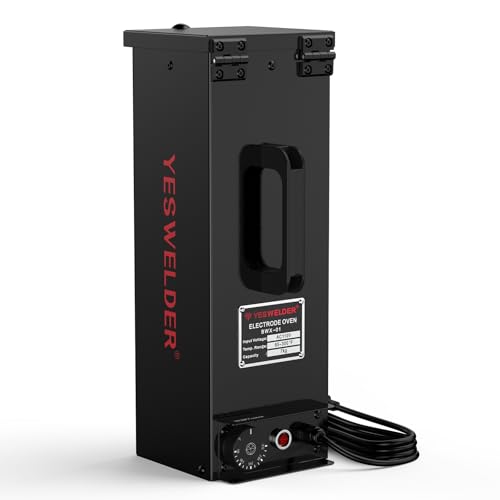
Low-hydrogen electrodes require controlled storage after opening. Many E7018 products are held around 250–300°F, but exposure limits and re-drying temperatures depend on the classification, moisture-resistant designation, manufacturer, and code. Use a dedicated electrode oven and the manufacturer’s storage instructions. Do not use a household food oven.
Products Worth Considering

Large Capacity: This VEVOR welding rod oven holds up to 10 lbs of 18-inch electrodes. It helps keep welding rods dry, reducing moisture-related cracking and arc instability — extending electrode lifespan and enhancing overall weld quality

MODEL: E7018 is a low-hydrogen iron powder type electrode that produces high quality x-ray welds. It can be used in all positions on AC or DC reverse polarity welding current.
Moisture Protection: Used to prevent moisture from contaminating your welding electrodes to maintain low hydrogen weld deposit properties and ensuring strong, crack-free welds
Safety Considerations When Welding Fillet Joints
Fillet joints often put your face close to corners where fumes and reflected ultraviolet radiation can concentrate. Wear a correctly shaded helmet, safety glasses, flame-resistant clothing, welding gloves, hearing protection when needed, and footwear suitable for hot work.
Use ventilation that keeps fumes out of your breathing zone. OSHA’s welding requirements address mechanical ventilation, confined spaces, coated metals, eye protection, and other hazards. Local exhaust should capture fumes near the arc without disturbing shielding gas.
Never use oxygen for ventilation. A “fresh-air hose” is not a do-it-yourself solution; supplied-air or air-purifying respiratory protection must be selected, fitted, and used under an appropriate respiratory-protection program.
Remove combustibles, protect nearby workers from arc flash, inspect leads and grounds, secure gas cylinders, and follow hot-work and fire-watch requirements. Treat painted, galvanized, plated, or unknown metal as a fume hazard until the coating is identified and controlled.
Use inspection methods suited to the job. Visual testing is common for fillet welds. Magnetic-particle or liquid-penetrant testing can reveal surface-breaking discontinuities when specified, while ultrasonic or radiographic methods have different limitations and applications. Dye penetrant is not automatically required on every critical fillet.
Pros and Cons of a Fillet Weld Rule of Thumb
Benefits
- Speeds early estimating and helps you choose a realistic practice setup.
- Reduces obvious underwelding or overwelding on noncritical shop projects.
- Encourages you to compare leg size with material thickness before striking an arc.
- Provides a starting point when building test coupons and tuning technique.
Limitations
- Does not account for exact load, eccentricity, fatigue, weld orientation, or base-metal limit states.
- Can conflict with minimum-size and edge-maximum provisions.
- Does not select filler, preheat, pass sequence, inspection, or welder qualification.
- Can create false confidence on safety-critical work.
For everyday gates, racks, tables, and practice coupons, a thickness-based estimate can be useful when paired with sound judgment. For trailers, machinery, structural members, and public-safety components, use the engineered requirement instead of relying on “what looks right.”
You now have a safer way to use the fillet weld size shortcut: estimate from the thinner part only for planning, check the common minimum from the thicker joined part, apply the edge maximum where relevant, and verify the total effective throat and length.
Keep a gauge at the bench, record successful settings, and practice on representative scrap. Consistent fit-up, correct fusion, controlled heat, and accurate measurement matter more than making the bead look oversized.
Frequently Asked Questions
What is the standard fillet weld size for 1/4-inch steel?
There is no single standard size for every 1/4-inch joint. Under the common AISC minimum table, a thicker joined part of exactly 1/4 inch has a 1/8-inch minimum fillet. The required weld may be larger because of load, weld length, fatigue, fit-up, the drawing, or the WPS.
Can I use the same fillet weld size rule for aluminum and steel?
No. Aluminum has different alloy, filler, oxide-cleaning, heat-input, and procedure requirements. Use the approved design and AWS D1.2 or the applicable aluminum code rather than copying a carbon-steel shortcut.
How do I know whether a fillet weld is too small?
Compare both measured legs, effective length, and profile with the drawing and acceptance criteria. Check for missed sections, undercut, overlap, cracks, porosity, and poor fusion. Use a fillet gauge; do not rely on bead width or a hammer sound.
What is the difference between fillet weld leg size and throat size?
Leg size is measured from the root to the toe along the joined surfaces. The effective throat is the shortest load-carrying distance from the root to the diagrammatic face. For a flat-faced equal-leg 90-degree fillet, the throat is about 0.707 times the leg.
Is overwelding a fillet joint ever acceptable?
A weld may exceed the nominal size within the drawing and code limits, but deliberate overwelding is usually wasteful. It can add distortion and residual stress without increasing the connection capacity. Follow the specified size and permitted profile.
Does the thicker or thinner plate control fillet weld size?
Both can control different checks. The thicker joined part controls the common structural-steel minimum-size table. The connected edge thickness controls the square-edge maximum. The engineering calculation controls the required throat and weld length.
Is a double fillet weld twice as strong as a single fillet?
Two identical weld lines provide twice the effective weld area of one line under a simple concentric comparison. Real joints may also have eccentricity, bending, prying, unequal load sharing, or base-metal limits, so total connection strength is not always exactly doubled.
Can intermittent fillet welds replace a continuous weld?
Only when the drawing or a qualified design allows them. Intermittent welds must meet required segment length, pitch, end conditions, strength, fatigue, corrosion, and sealing requirements. Do not invent a skip-weld pattern at the bench.
Sources
- AISC 360, Specification for Structural Steel Buildings — structural-steel weld design framework, minimum sizes, and detailing limits
- AISC Weld Reliability Analysis — effective throat, weld strength equations, resistance factors, and inspection discussion
- American Welding Society D1 Committee — current AWS D1.1 steel, D1.2 aluminum, and D1.6 stainless structural welding codes
- OSHA 29 CFR 1910.252 — ventilation, eye protection, coatings, and general welding safety requirements
- Miller: Setting Correct MIG Parameters — choosing and fine-tuning voltage and wire feed
- Miller: Common Stick Electrode Questions — E7018 selection and low-hydrogen storage guidance