
Welding polarity determines which side of a direct-current welding circuit is positive and which is negative. That choice changes arc behavior, metal transfer, penetration, electrode performance, bead shape, and tungsten life. The correct setting comes from the welding process, the exact electrode or wire, the machine manual, and any welding procedure specification that applies.
Quick Answer
Use the polarity printed on the electrode package, wire spool, welder chart, or approved welding procedure. Solid-wire MIG normally uses DCEP, DC TIG on steel normally uses DCEN, and flux-core polarity depends on the exact wire. Do not reverse polarity only to reduce heat on thin metal.
Key Takeaways
- DCEP, DC+, and EP mean the electrode is positive and the work lead is negative.
- DCEN, DC−, and EN mean the electrode is negative and the work lead is positive.
- Solid-wire MIG normally uses DCEP, while DC TIG on steel and stainless steel normally uses DCEN.
- Self-shielded and gas-shielded flux-core wires do not share one universal polarity. Read the spool or datasheet.
- AC alternates between electrode positive and electrode negative and is commonly used for TIG welding aluminum and magnesium.
- A good-looking test bead can reveal setup problems, but appearance alone cannot prove internal fusion or penetration.
At a Glance
| Time Required | About 2 to 5 minutes to identify and set the required polarity |
| Difficulty | Easy, but the setting must match the process and consumable |
| Tools Needed | Welder manual, electrode or wire label, work clamp, electrode holder or gun lead, scrap metal, and welding PPE |
| Cost | Usually $0 if the welder supports the required current type and polarity |
What Is Welding Polarity?
Polarity identifies how the electrode lead and work lead are connected to a DC welding power source. Changing those connections changes how the arc, electrode, filler metal, and weld pool behave. Miller’s welding polarity guidance defines the two fixed DC arrangements as DC electrode positive and DC electrode negative.
DCEP stands for Direct Current Electrode Positive. The electrode holder, MIG gun lead, or wire-feed lead is connected to positive, and the work lead is connected to negative. DCEP is also called electrode positive, DC+, EP, or reverse polarity.
DCEN stands for Direct Current Electrode Negative. The electrode holder, TIG torch lead, or wire-feed lead is connected to negative, and the work lead is connected to positive. DCEN is also called electrode negative, DC−, EN, or straight polarity.
AC stands for alternating current. It does not remain electrode positive or electrode negative. Instead, the polarity changes repeatedly during the cycle. AC is used for certain stick electrodes and is the common TIG choice for aluminum and magnesium.
Polarity affects penetration, arc stability, transfer behavior, electrode melt-off, deposition, bead profile, spatter, slag behavior, and tungsten temperature. These effects are process-specific, so a rule that works for TIG cannot automatically be applied to MIG, stick, or flux-core welding.
Note: Polarity and amperage are different settings. Polarity controls the positive and negative sides of the circuit. Amperage controls current level. Voltage, wire speed, arc length, travel speed, joint design, and shielding also affect the finished weld.
Welding Polarity: DCEP vs. DCEN
The terminal connection is simple: DCEP means electrode positive, and DCEN means electrode negative. The practical result is less universal because a coated stick rod, solid MIG wire, flux-core wire, and nonconsumable TIG tungsten respond differently.
The package, spool, product datasheet, machine chart, or approved welding procedure outranks any general polarity chart.
DCEP: Electrode Positive
With DCEP, the electrode side of the circuit is positive. It is the normal polarity for solid-wire GMAW and a common choice for many SMAW electrodes. In those applications, DCEP often supports stable transfer, good tie-in, and stronger effective penetration than running the same suitable process on DCEN.
Common examples include many E7018 products, E6010 products, and solid steel MIG wires. For example, Lincoln Electric lists DC+ as the preferred polarity for its Excalibur 7018 MR electrode. That example does not make DCEP correct for every rod carrying a similar-looking classification; the package instructions still control.
DCEN: Electrode Negative
With DCEN, the electrode side is negative. It is the normal DC TIG setting for steel, stainless steel, nickel alloys, titanium, and many other metals. DCEN helps maintain a focused arc and places far less thermal stress on the tungsten than continuous DCEP.
Some self-shielded flux-core wires and selected stick electrodes also require or permit DCEN. The choice is tied to the consumable design, not merely to material thickness.
AC: Alternating Current
AC alternates between electrode-positive and electrode-negative portions of the cycle. In AC TIG welding on aluminum, the electrode-positive portion helps disrupt the oxide layer, while the electrode-negative portion supplies useful penetration and reduces heat loading on the tungsten. Modern AC TIG machines may also let the operator adjust balance and frequency.
AC can also reduce some forms of DC arc blow and can be used with stick electrodes specifically rated for AC. It should not be selected unless the electrode and machine support it.
Choosing the Right Polarity
Choose polarity in this order:
- Identify the welding process.
- Read the electrode package, wire spool, or product datasheet.
- Check the welder’s connection diagram or process menu.
- Follow the applicable welding procedure specification when one is required.
- Confirm that the selected current type and polarity match the consumable.
- Set the remaining parameters for the metal thickness and joint.
- Run a test bead on comparable scrap before welding the final part.
If the arc behaves badly, stop and verify the setup. Do not continue depositing weld metal over a bead that already shows poor tie-in, severe spatter, or an unstable arc.
DCEP vs. DCEN by Welding Process
The following table is a starting point, not a substitute for a wire datasheet, electrode package, machine manual, or WPS.
| Process | Common Setting | What Controls the Choice |
|---|---|---|
| Stick welding (SMAW) | Often DCEP; some rods also allow AC or DCEN | Electrode classification, brand-specific package, and WPS |
| Solid-wire MIG (GMAW) | Normally DCEP | Wire type, shielding gas, transfer mode, and machine chart |
| DC TIG on steel and stainless steel | Normally DCEN | Base metal, tungsten size, amperage, and machine manual |
| TIG on aluminum or magnesium | Normally AC | Machine capability, oxide condition, AC balance, frequency, and procedure |
| Self-shielded flux-core (FCAW-S) | Often DCEN, but some wires require DCEP | Exact wire classification, spool label, and datasheet |
| Gas-shielded flux-core (FCAW-G) | Often DCEP | Wire datasheet, shielding gas, and WPS |
| AC stick welding | Polarity alternates | AC-rated electrode and machine capability |
Why DCEP Often Gives Deeper Penetration
In many common consumable-electrode applications, especially SMAW and solid-wire GMAW, Direct Current Electrode Positive produces stronger effective penetration than DCEN. Arc force, transfer behavior, electrode coating, shielding, wire chemistry, joint shape, and operating parameters all contribute to the result.
Avoid reducing the explanation to a fixed claim that a certain percentage of heat always enters one side of the circuit. Heat distribution varies with the process and arc conditions. The useful shop-level rule is that DCEP is commonly selected where the approved electrode or wire is designed to provide stable transfer and good fusion.
DCEP is therefore common for fillet welds, groove welds, medium or thick steel, and joints where lack of fusion would be unacceptable. Polarity alone cannot correct poor joint preparation, low amperage, excessive travel speed, contamination, or an unsuitable electrode.
For related wire setup and technique, review these flux-core welding setup tips.
Does DCEN Help on Thin Metal?
DCEN is not a universal thin-metal setting. It can produce a different penetration or deposition pattern in some stick and flux-core applications, but it should be used only when the exact electrode or wire supports it. Reversing solid-wire MIG from DCEP to DCEN is not a proper substitute for lowering heat input.
For TIG welding steel or stainless steel, DCEN is already the normal polarity whether the material is thin or thick. Heat is then controlled with amperage, pulse settings when available, travel speed, arc length, filler addition, joint fit-up, and the duration of each weld.
For thin sheet, use the approved polarity and control burn-through by lowering the settings within the consumable’s usable range, improving fit-up, using short stitches or spaced tacks where appropriate, moving efficiently, and allowing the panel to cool. Joint design and weld size also matter, so compare the planned joint with these fillet weld size considerations.
Warning: Do not reverse polarity as an experiment on a structural, pressure-retaining, suspension, steering, rollover, lifting, or other safety-critical weld. Follow the approved WPS, repair procedure, and consumable requirements.
TIG Welding Polarity
In TIG welding, DCEN is normally used for steel, stainless steel, nickel alloys, titanium, copper, and many other metals. The tungsten is connected to negative, and the work lead is connected to positive. This arrangement gives a focused arc and helps prevent rapid tungsten overheating.
Continuous DCEP is rarely used for ordinary TIG welding. It subjects the tungsten to heavy thermal loading, reduces its current-carrying capacity, and generally produces a shallow weld. If a tungsten balls excessively, melts back, spits particles into the puddle, or becomes unstable soon after starting, verify polarity, tungsten size, shielding gas, and amperage.
AC is normally used for manual TIG welding of aluminum and magnesium. The EP portion contributes oxide-cleaning action, while the EN portion supplies penetration and reduces tungsten heating. Miller’s AC balance guide for aluminum TIG explains how changing the EN/EP balance affects cleaning, penetration, and tungsten behavior.
Tungsten type, diameter, preparation, and current capacity must also match the application. Compare the setup with the Miller tungsten electrode guide.
MIG Welding Polarity
In MIG welding with solid wire and shielding gas, DCEP is the normal setup. The gun or wire-drive lead is positive, and the work lead is negative. Lincoln Electric’s official WELD-PAK manual, for example, specifies DC+ for GMAW and DC− for its recommended NR-211-MP self-shielded wire.
Correct polarity supports stable wire melting and transfer, but it does not compensate for incorrect voltage, wire speed, contact-tip-to-work distance, gun angle, shielding gas, or travel speed.
Poor gas coverage can cause porosity even when polarity is correct. Keep the nozzle clean, use the specified gas and flow range, check for leaks, and shield the weld from drafts. Do not add shielding gas to a self-shielded wire unless the wire manufacturer specifically requires it.
A flux-core wire running through a MIG-style machine is still an FCAW consumable. Do not assume that it uses the same polarity as solid MIG wire.
Products Worth Considering

🍨【Easy and Quick Welding】HIZONE ER70S-6 solid wire has the highest combination of manganese and silicon deoxidizers, permitting higher welding currents with 100% CO2 shielding gas. Install it then you can weld all positions welding including T-joints, butt welds, and lap welds. Great for construction work, farm implement fabrication, shaft buildup, tanks, truck bodies and general shop applications with poor fit-up or rusty, oily plates.

0.035" 11LBS MIG Welding Wire: VEVOR 0.035" 11LBS ER70S-6 solid MIG welding wire is suitable for a wide range of carbon steel applications. Compared to other standard MIG welding wires, it combines higher levels of manganese and silicon, creating high-quality welds even when working with dirty, oily, or rusted steel.

High-quality: ARCCAPTAIN's ER70S-6 mig welding wire .030" meets industry standards(Net Weight: 10lbs), ensuring consistent performance, superior strength. With its smooth feeding and stable welding parameters, you can achieve optimal penetration, high deposition rates, and exceptional overall welding performance.
Stick Welding Polarity
With stick welding, polarity depends on the electrode coating and classification. Many common rods are run on DCEP, while others can use AC, DCEP, DCEN, or more than one option. The package or manufacturer datasheet states the supported current type and preferred polarity.
Many E7018 electrodes are commonly run on DCEP and may also be AC-capable. E6010 products are commonly associated with DCEP. Other electrodes, such as certain E6011 or E6013 products, may offer different current options. Never infer the final setting from a partial classification alone when the product instructions are available.
Changing from DCEP to DCEN can alter arc force, penetration, deposition, slag behavior, bead shape, and puddle control. In code work, any change must remain within the qualified procedure.
If a stick welder will not establish or maintain an arc, also check amperage, rod condition, work-clamp contact, cable condition, arc length, and electrode and setup problems.
Products Worth Considering

MODEL: E6013 is a mild-steel general purpose rod. It operates on AC or DC welding current and works well on low voltage AC machines.

E7018 Welding Rod: Diameter: 3/32''; Length: 14"; Weight: 5 lb.
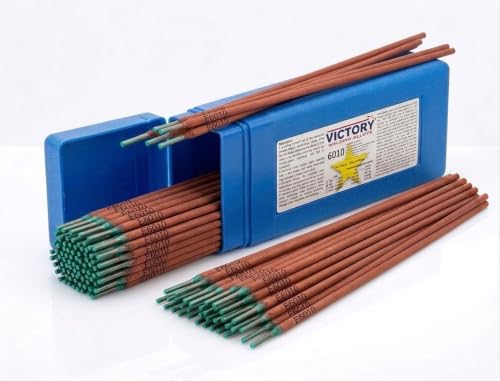
A strong forceful arc of this electrode creates deeply penetrating welds, while the fast freeze characteristic allows it to be used in any position including vertical-up, vertical-down, overhead, and flat or horizontal
Flux-Core Welding Polarity
Flux-core welding has no single universal polarity. Many self-shielded wires use DCEN, while many gas-shielded wires use DCEP. There are exceptions in both groups, so the spool label or product datasheet must decide.
For example, Lincoln’s NR-211-MP instructions call for DC−. Other self-shielded classifications can require electrode positive. Gas-shielded flux-core wires are often DCEP, but a general chart should never override the wire manufacturer.
Wrong polarity can make a flux-core arc harsh or unstable, increase spatter, create a high rope-like bead, disrupt slag coverage, reduce tie-in, or make the puddle difficult to control. Porosity may also appear, but first rule out moisture, contamination, incorrect gas, leaks, drafts, and excessive stickout.
Self-shielded FCAW is useful outdoors because it does not rely on an external shielding-gas envelope. Wind can still disturb the arc and slag, and fumes can accumulate in enclosed or poorly ventilated areas.
AC vs. DC and Arc Blow
DC usually provides a smoother arc and lets the operator select a fixed electrode-positive or electrode-negative arrangement. Its fixed direction can also make the arc more sensitive to magnetic fields in the workpiece.
Arc blow is unwanted arc deflection that can occur during DC welding. It may appear near corners, at the ends of joints, around magnetized parts, or where the return-current path creates an uneven magnetic field. Symptoms include an arc that bends away from the joint, erratic spatter, undercut, and poor sidewall tie-in.
If polarity is correct but the arc still wanders, try moving the work-clamp location, shortening the arc, changing the welding sequence or direction, using run-on or run-off tabs where suitable, reducing residual magnetism, or using AC when the electrode and procedure permit it. Do not reverse polarity unless the consumable allows that setting.
How to Choose Welding Polarity
Choosing welding polarity begins with the process and consumable, not metal thickness alone. Electrode coatings and wire formulations are designed to operate within a specific current and polarity range.
- Identify the process: Determine whether the setup is TIG, solid-wire MIG, stick, self-shielded flux-core, gas-shielded flux-core, or another process.
- Read the consumable label: Look for DCEP, DCEN, DC+, DC−, EP, EN, AC, or a process-specific connection diagram.
- Check the machine manual: Confirm which terminal, internal stud, selector switch, or menu setting controls the electrode lead.
- Check the procedure: For qualified or safety-critical work, use the polarity required by the WPS or repair procedure.
- Set the remaining variables: Match amperage, voltage, wire speed, gas, stickout, and technique to the joint and thickness.
- Test on comparable scrap: Use the same metal type, thickness, position, and joint preparation when practical.
- Evaluate the result: Check arc stability, spatter, bead profile, tie-in, slag release, and consumable behavior.
Pro Tip: Write the required polarity and gas on the spool, rod container, or setup card. That habit helps prevent lead-swap errors when one machine alternates between solid MIG, flux-core, TIG, and stick work.
How to Read Polarity Labels and Machine Markings
Manufacturers use several abbreviations for the same two DC arrangements. Match the label to the electrode side of the circuit.
| Marking | Meaning | Lead Arrangement |
|---|---|---|
| DCEP, DC+, EP, reverse polarity | Electrode positive | Electrode, gun, or wire-drive lead to +; work lead to − |
| DCEN, DC−, EN, straight polarity | Electrode negative | Electrode, torch, or wire-drive lead to −; work lead to + |
| AC | Alternating current | Polarity alternates; use only with an AC-capable machine and compatible process |
Some multiprocess machines have external DINSE terminals. Others place the polarity changeover studs inside the wire compartment. Inverter machines may use a process menu or perform the change internally. Never assume that selecting “MIG,” “flux-core,” or “TIG” changes the physical connections unless the manual confirms it.
Note: The work clamp completes the welding circuit and is sometimes casually called a ground clamp. It is not the same as the machine’s protective equipment-grounding conductor. Use the terms and connection instructions in the welder manual.
What Happens When Polarity Is Wrong?

If you use the wrong polarity, the arc often gives an immediate warning. It may sound harsh, wander, spit, repeatedly extinguish, or feel weak. The electrode or wire may melt in an unusual way, and the bead may become high, narrow, irregular, or poorly tied into the base metal.
Possible symptoms include:
- Poor tie-in, shallow fusion, or an unusually high bead
- Excessive spatter
- Unstable starts or repeated arc outages
- Rope-like or irregular bead shape
- Abnormal slag coverage or difficult slag removal
- Poor wire transfer or puddle control
- Rapid tungsten overheating or melting in TIG welding
- Porosity or inclusions when polarity disrupts transfer or slag behavior, although gas and contamination should also be checked
A bad bead is not always caused by polarity, but polarity is one of the first setup items to verify when the arc suddenly behaves differently.
Do not cover a defective test bead with another pass and assume the problem is solved. Correct the setup, remove defective weld metal when required, prepare the surface again, and retest.
How to Set Polarity on Your Welder
Warning: Switch off and isolate the welder as directed by its manual before moving output leads or opening a polarity compartment. Wear suitable welding PPE, provide ventilation, protect nearby people from arc rays, and remove combustible materials. Welding can cause burns, eye injury, harmful fume exposure, fire, and electric shock. Review OSHA welding hazards and controls.
Once the required polarity is known, set the machine deliberately. Welder layouts vary, so the markings and manual for the specific unit take priority.
- Turn the machine off. Follow the manual’s shutdown and isolation instructions before touching output connections.
- Locate the polarity controls. Find the positive and negative output terminals, internal changeover studs, selector switch, or digital process setting.
- For DCEP: connect the electrode holder, MIG gun lead, or wire-drive lead to positive. Connect the work lead to negative.
- For DCEN: connect the electrode holder, TIG torch lead, or wire-drive lead to negative. Connect the work lead to positive.
- For AC: select an AC-capable process and follow the machine instructions. Do not try to create AC by swapping DC leads.
- Secure every connection. Loose output connections can create resistance, heat, erratic performance, and damaged connectors.
- Recheck the label and procedure. Confirm that the installed rod or wire matches the selected current and polarity.
- Make a controlled test weld. Use comparable scrap and inspect arc behavior and visible bead characteristics before starting the final joint.
You also need the right amperage or wire settings for the electrode size and material. For SMAW setup ranges, compare the machine and rod instructions with this stick welding amperage chart.
Welding Polarity Tips and Fixes
| Symptom | Possible Cause | Fix |
|---|---|---|
| Arc is harsh and spattery | Polarity may not match the wire or rod | Check the product label, correct the connections with power off, and retest on scrap |
| Bead sits high with weak sidewall tie-in | Wrong polarity, low settings, excessive travel speed, or poor joint preparation | Verify polarity first, then correct settings, angle, travel speed, cleanliness, and fit-up |
| Tungsten overheats or melts back | DC TIG may be set to DCEP, or the tungsten may be undersized | Use DCEN for normal DC TIG work, or the specified AC setup for aluminum; check tungsten size and gas coverage |
| Flux-core bead looks rope-like | Wrong polarity, excessive stickout, low voltage, or poor technique | Identify the exact wire, set its specified polarity, and reset parameters from the datasheet |
| Arc will not remain stable | Polarity, work-clamp contact, cable condition, settings, or contamination may be wrong | Verify polarity, clean the clamp point, tighten connections, and reset the process parameters |
| Arc bends away from the joint | DC arc blow or an unfavorable return-current path | Move the work clamp, shorten the arc, change sequence or direction, and use AC only when permitted |
| Porosity appears | Shielding loss, contamination, moisture, excessive stickout, or disrupted transfer | Check gas, leaks, drafts, cleanliness, consumable condition, stickout, and polarity |
Swap leads only after confirming that the consumable calls for the opposite polarity. If the polarity is already correct, inspect cleanliness, cable connections, work-clamp placement, arc length, stickout, voltage, amperage, gas flow, travel angle, and travel speed.
How to Verify the Weld After Correcting Polarity
A test bead is useful for confirming that the arc sounds and behaves normally. It can reveal excessive spatter, unstable transfer, abnormal slag, poor visible tie-in, undercut, overlap, and an obviously unsuitable bead profile.
However, the outside of a bead cannot prove internal penetration, root fusion, sidewall fusion, or freedom from hidden inclusions. For noncritical practice work, a bend test, break test, fillet-break test, or polished and etched cross-section can show more than visual inspection alone when performed safely and correctly.
For structural, pressure, transportation, lifting, or other safety-critical work, follow the governing code, approved WPS, repair instructions, and inspection plan. Required examination may include visual testing by qualified personnel, liquid penetrant, magnetic-particle testing, ultrasonic testing, radiography, or destructive qualification tests.
Frequently Asked Questions
Do you stick weld on DC positive or DC negative?
Many stick electrodes are commonly run on DC positive, especially rods designed for strong penetration and arc force. Other electrodes can use AC, DC positive, DC negative, or more than one option. Read the package and follow the approved procedure.
Do you run 7018 on DC positive or negative?
Many E7018 electrodes use DCEP as their preferred DC polarity, and many products are also AC-capable. Verify the exact package because electrode formulation, moisture classification, manufacturer instructions, and the welding procedure control the permitted setting.
What does polarity determine in DC welding?
Polarity determines whether the electrode side of the DC circuit is positive or negative. That setting can change arc stability, transfer, penetration, electrode melt-off, deposition, bead shape, spatter, slag behavior, and tungsten temperature.
What is the difference between DC positive and DC negative?
DC positive means the electrode is connected to the positive output and the work lead to negative; this is DCEP. DC negative means the electrode is connected to negative and the work lead to positive; this is DCEN. Their effects depend on the process and consumable.
Is flux-core welding DCEN or DCEP?
It depends on the wire. Many self-shielded flux-core wires use DCEN, while many gas-shielded wires use DCEP. Exceptions exist, so use the polarity printed on the spool label or product datasheet.
What polarity is used for TIG welding steel?
TIG welding steel normally uses DCEN, with the tungsten connected to negative and the work lead connected to positive. This produces a focused DC arc and helps keep the tungsten from overheating.
Why is AC commonly used for TIG welding aluminum?
AC alternates between electrode positive and electrode negative. The electrode-positive portion helps remove the aluminum oxide layer, while the electrode-negative portion contributes penetration and reduces heat loading on the tungsten.
Is the work clamp the same as an electrical ground?
No. The work clamp completes the welding-current circuit between the workpiece and power source. It is sometimes casually called a ground clamp, but it is not automatically the same as the equipment-grounding conductor used for electrical safety.
Can reversed polarity damage a welder?
Swapping approved output connections on a machine designed for both polarities normally does not damage the power source when done correctly with the machine off. Wrong polarity can damage or overheat consumables, produce poor welds, and harm connectors if leads are loose. Never alter a fixed-polarity machine outside its manual.
Conclusion
Welding polarity is a small setup choice with a major effect on arc performance and weld quality. Use DCEP when the process, wire, electrode, or WPS calls for electrode positive. Use DCEN when it calls for electrode negative, including normal DC TIG work on steel. Use AC only with a compatible machine and process, such as common aluminum TIG setups. For flux-core and stick welding, never guess from habit or thickness alone: read the exact consumable instructions. When the arc sounds wrong or the bead behaves unusually, verify polarity early, then check the rest of the setup.
Sources
- Miller Welding Polarity Switches Made Easy — supports DCEP/DCEN definitions, common process settings, and wrong-polarity effects.
- Lincoln Electric AC/DC Understanding Polarity — supports stick-electrode polarity principles, penetration differences, and electrode-specific selection.
- Lincoln Electric WELD-PAK 100 Manual — provides official examples of DC+ solid-wire GMAW and DC− NR-211-MP self-shielded FCAW connections.
- Lincoln Electric Excalibur 7018 MR Product Data — supports the product-specific DCEP and AC example for E7018 electrodes.
- Miller AC Balance Control for TIG Aluminum — supports AC cleaning, penetration, balance, and tungsten behavior.
- OSHA Welding, Cutting, and Brazing Hazards and Solutions — supports precautions for fumes, ultraviolet radiation, burns, eye injury, and electrical hazards.




