
When you compare a fillet weld vs groove weld, the main difference is where the weld metal is placed and how the joint transfers load. A fillet weld is deposited in the corner formed by two members. A groove weld is deposited in a groove between workpiece surfaces, which may be square-edged, beveled, curved, or naturally formed. Neither type is automatically stronger; the correct choice depends on the drawing, effective throat, penetration requirement, material, access, service conditions, and governing code.
Quick Answer
Use a fillet weld for many tee, lap, and corner joints when a properly sized effective throat can carry the design load. Use a groove weld when the joint needs a specified PJP or CJP effective throat, edge-to-edge joining, deeper access to the root, or a code-required detail.
Key Takeaways
- Fillet welds usually need less edge preparation and are often economical for smaller, accessible joints.
- Groove welds may use square, V, bevel, U, J, or flare preparations and can be designed for partial or complete joint penetration.
- Strength comes from the complete connection design, including effective throat, weld length, load direction, filler metal, base metal, workmanship, and inspection.
- CJP and PJP are groove-weld designations. CJP extends through the joint thickness at the weld; PJP has a specified effective throat less than the full joint thickness.
- The drawing, WPS, applicable code, and engineer-approved detail control safety-critical work.
At a Glance
| Typical Joint Use | Fillet welds: tee, lap, and corner joints. Groove welds: butt joints plus selected tee, corner, edge, pipe, and curved-member joints. |
| Preparation | Fillet welds usually need clean fit-up and access. Groove welds may also need edge preparation, root-opening control, backing, back gouging, or multiple passes. |
| Strength Basis | Fillet weld: effective throat, effective length, and load direction. Groove weld: specified effective throat, joint penetration, weld area, and connection design. |
| Inspection | VT is common for both. MT, PT, UT, RT, or other examination may be required by the code, drawing, specification, or inspection plan. |
| Relative Cost | Fillet welds are often less expensive for smaller weld sizes. Groove weld cost rises with preparation, weld volume, passes, access, qualification, and examination. |
What Is a Fillet Weld and When to Use It?
A fillet weld has a roughly triangular cross-section and is deposited in the corner formed by two members. It is common on tee, lap, and corner joints. The weld joins the two surfaces without requiring the edges to form a conventional butt-joint groove.
Fillet-weld design uses several geometry terms:
- Leg: The distance from the weld root to a weld toe along a member surface.
- Root: The point where the back of the weld intersects the base-metal surfaces.
- Toe: The junction between the weld face and base metal.
- Face: The exposed surface of the finished weld.
- Effective throat: The shortest design distance through the weld that resists the applied load.
For an equal-leg fillet weld made in a 90-degree joint, the theoretical throat is about 0.707 times the leg size. That relationship does not cover every skewed joint, unequal-leg weld, root gap, or code allowance, so the drawing and governing standard still control.
You use fillet welds when the joint geometry allows the specified throat and length to transfer the load. Common examples include brackets, tabs, stiffeners, cover plates, frames, supports, and many shop-fabricated steel parts.
Fillet welds are popular because fit-up is often simple. The members still need clean surfaces, acceptable alignment, enough access, and the required root condition, but they commonly avoid the beveling used for many groove welds.
Pro Tip: Do not increase a fillet weld just because a larger bead looks stronger. Oversizing adds arc time, filler metal, heat, shrinkage, and distortion. Use the weld size and length on the approved drawing or required by the connection design.
Fillet Weld Contours, Length Patterns, and Positions
Several terms that are often called “types” of fillet weld actually describe different features. Flat, concave, and convex describe the face contour. Continuous and intermittent describe how much of the joint length is welded. Flat, horizontal, vertical, and overhead can also describe welding position, which is a separate issue.
- Flat contour: The face is approximately flat between the toes. This is a contour requirement, not the same as welding in the flat position.
- Concave contour: The face curves inward. Excessive concavity can leave less throat than required.
- Convex contour: The face curves outward. Excessive convexity adds weld metal and may create a sharper toe transition.
- Intermittent fillet weld: Short weld segments are separated by unwelded spaces. The drawing should specify segment length, pitch, side, and arrangement.
- Continuous fillet weld: The weld continues for the full specified length. It may be selected for strength, stiffness, sealing, corrosion control, or another design reason.
For best results, clean the base metal, remove coatings that interfere with welding, control fit-up, and follow the approved procedure. Good surface preparation helps reduce porosity, lack of fusion, and coating-related fume hazards.
Understanding Groove Welds and Their Applications
A groove weld is deposited in a groove between workpiece surfaces. The groove may be created by a root opening, beveling, machining, thermal cutting, or the natural shape of curved material. This is why a square groove can have little or no bevel, while flare grooves use rounded surfaces.
Groove welds are common in butt joints, plate splices, pipe, heavy equipment, and structural details that need a specified effective throat. They can also appear in tee and corner joints, so “fillet equals tee joint” and “groove equals butt joint” are useful shortcuts but not absolute rules.
The two main joint-penetration designations are:
- CJP, or complete joint penetration: A groove weld in which weld metal extends through the joint thickness at the weld. The completed connection must still meet the applicable design, procedure, workmanship, and inspection requirements.
- PJP, or partial joint penetration: A groove weld with an effective throat that is less than the full thickness of the joint. Its required size is established by design and shown in the welding symbol or detail.
Groove welds may require control of the groove angle, root opening, root face, backing, back-gouging method, preheat, pass sequence, interpass cleaning, heat input, and distortion. The exact variables belong in the drawing and WPS rather than being chosen by appearance.
Note: A groove weld is not automatically the best or strongest choice. A properly designed fillet weld can develop the required connection strength and may use less preparation, labor, and inspection.
Products Worth Considering

7piece Fillet Weld Set Gage Rl Gauge
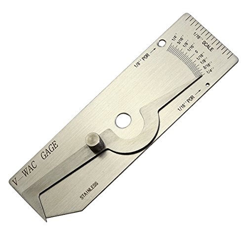
V-WAC Single Weld Gage

Made of high-quality stainless steel material, with a reasonable structure, beautiful appearance, convenient use, high efficiency and durability, and anti-corrosion and wear-resistant properties.
Common Groove-Weld Preparations
Selecting a groove preparation involves access, thickness, process capability, required effective throat, distortion control, and weld-metal volume. Common groove-weld forms include:
- Square groove weld: Uses square edges, with a tight fit or specified root opening. It is often practical on thinner material or with a process that can achieve the required root fusion.
- V-groove weld: Both members are beveled to form a V. This improves access to the root but can require substantial filler metal on thick sections.
- Bevel groove weld: One member is beveled and the other remains square. The arrow on the welding symbol may identify the member that receives the preparation.
- U-groove weld: Both edges receive a curved preparation. It can reduce weld-metal volume on thick material, but preparation is more difficult and costly.
- J-groove weld: One member receives a curved J preparation while the mating member remains square. It can reduce weld volume but needs accurate preparation.
- Flare-V groove weld: The groove is formed by two rounded or curved surfaces.
- Flare-bevel groove weld: The groove is formed by one rounded surface and one flat surface.
Single-groove details provide access from one side. Double-groove details divide the weld between both sides and can reduce weld volume and angular distortion, but they require access to both faces. Backing, back gouging, or welding from both sides may be used when the approved detail requires them.
Groove-weld details are tied to the welding symbol, WPS, and governing code. If the drawing calls for CJP, PJP, backing removal, back gouging, a specific contour, or a defined examination method, do not substitute another joint without approval.
Products Worth Considering

Angle of Preparation, 0° to 60° and Excess Weld Metal (capping size)

PASS X-RAY INSPECTIONS WITH CONFIDENCE: Designed to cut radiographic rejects by accurately measuring internal misalignment after fit-up. Delivering professional-grade precision up to ±0.001 inches, this gauge is NBS calibration capable, making it the trusted choice for Certified Welding Inspectors (CWI) and serious pipefitters.

Measures type------ The Bridge Welding Gauge can be used for measuring Weld Reinforcement, and this bridge cam gage can alse measure Fillet Weld Leg Length or Fillet Weld Throat Dimension; The bridge cam gauge will help you measure Undercuts and Pits as well. And this bridge cam welding gauge will good in measuring Angle of Preparation or measuring Outside Misalignment. If you want to know the specific measure range and method, please reference the photo or description.
Fillet Weld vs Groove Weld: Quick Comparison
| Category | Fillet Weld | Groove Weld |
| Basic form | Roughly triangular weld deposited in a corner between members | Weld deposited in a groove between workpiece surfaces |
| Common joints | Tee, lap, corner, brackets, tabs, and stiffeners | Butt, tee, corner, edge, pipe, and curved-member joints |
| Design basis | Effective throat, effective length, weld strength, and load direction | Specified effective throat, PJP or CJP requirement, weld strength, and load path |
| Preparation | Usually clean fit-up without edge beveling | May need root opening, beveling, machining, backing, or back gouging |
| Time and cost | Often faster and less expensive for smaller welds | Often higher due to preparation, passes, access, and examination |
| Best choice when | The joint permits a properly sized throat and no groove detail is required | The drawing requires a groove, PJP, CJP, edge-to-edge joint, or specific root access |
Comparing Strength and Durability: Fillet vs Groove Welds
Weld type alone does not determine strength. A small or poorly fused groove weld can be weaker than a correctly sized fillet weld. A CJP groove weld can provide a through-thickness load path, but a fillet weld or PJP groove weld can also be designed to develop the required connection strength. The engineer evaluates the whole connection, not the weld name by itself.
Strength Comparison
A fillet weld carries load through its effective throat and effective length. Weld size, weld-group geometry, force direction, eccentricity, and the strength of both weld and base metal matter. On an equal-leg 90-degree fillet, increasing the leg increases the throat, but it also increases weld-metal volume quickly.
A groove weld uses its specified effective throat and fused area. A CJP groove weld extends through the joint thickness at the weld. A PJP groove weld has a smaller specified effective throat and may be economical when full joint penetration is unnecessary.
Do not treat PJP as a simple midpoint between fillet and CJP welds. Fillet and PJP welds have different geometries, stress paths, symbols, and design rules. Either can be adequate when properly detailed.
Durability and Fatigue Assessment
Durability depends on stress range, load cycles, weld profile, toe transition, root condition, discontinuities, corrosion, temperature, and service environment. A smooth transition and sound fusion usually matter more than adding unnecessary weld metal.
Fillet welds perform well in many static and cyclic applications, but undercut, overlap, lack of fusion, abrupt starts and stops, and poor end returns can reduce performance. Groove welds can provide a direct load path, yet incomplete root fusion, slag between passes, misalignment, or poor backing removal can create serious problems.
Fatigue-sensitive details need more than a general “stronger weld” rule. The engineer must consider the joint category, stress direction, root and toe conditions, inspection level, and any code-specific detailing restrictions.
The strongest weld is not always the biggest weld. It is the weld that matches the load path, approved detail, material, procedure, workmanship, and inspection requirement.
Cost and Time for Each Weld Type
Cost and time often influence the final detail after strength and code requirements are satisfied. Fillet welds are commonly economical because the parts can often be cleaned, fitted, tacked, and welded without beveling. Groove welds may need cutting, machining, grinding, root-gap control, backing, multiple passes, back gouging, and more examination.
That does not mean every fillet weld is cheaper. A very large fillet weld can use more filler metal than a well-designed groove preparation. Welding position, process deposition rate, access, fit-up tolerance, preheat, distortion correction, and local labor rates can change the result.
Labor and Skill Requirements
Fillet welds are often easier to repeat in favorable positions, but they still require correct angle, travel speed, fusion at both legs, and profile control. Vertical and overhead fillets can be demanding.
Groove welds usually require tighter control of the root pass, sidewall fusion, pass sequence, interpass cleaning, heat input, and distortion. Code work may also require qualified procedures, qualified welders, documented consumable control, and inspection records.
Material Preparation Time
Preparation is where groove welds often add the most time. The work may include beveling, setting a specified root opening, controlling the root face, installing backing, aligning high-low mismatch, and planning access from one or both sides.
| Weld Type | Typical Material Preparation |
| Fillet Weld | Clean metal, acceptable fit-up, correct tack welds, required root condition, and torch or electrode access. |
| Groove Weld | May include beveling, machining, root-opening control, backing, multiple passes, interpass cleaning, and back gouging. |
For related process choices, see how flux-cored welding wire types and TIG welding techniques affect deposition rate, penetration profile, access, and finish.
Inspection and Quality Control
Inspection must follow the drawing, WPS, governing code, owner specification, and service risk. Do not assume fillet welds are always visual-only or that every groove weld requires radiography.
Quality control begins before welding. The inspector may need to verify material identification, joint preparation, fit-up, consumables, preheat, WPS variables, welder qualification, tack welds, backing, and environmental conditions. In-process checks may cover interpass temperature, cleaning, pass sequence, and visible discontinuities.
Common examination methods include:
- VT, or visual testing: Evaluates visible size, length, profile, cracks, undercut, overlap, arc strikes, and surface condition. VT also includes fit-up and in-process checks when required.
- PT, or liquid penetrant testing: Detects surface-breaking discontinuities on suitable nonporous materials.
- MT, or magnetic particle testing: Detects surface and near-surface discontinuities in ferromagnetic materials.
- UT, or ultrasonic testing: Uses sound energy to evaluate internal reflectors and is often applied to suitable groove welds.
- RT, or radiographic testing: Uses X-rays or gamma radiation to produce an image of internal conditions where the method, geometry, access, and safety controls permit.
Acceptance criteria are not interchangeable. A visible indication or NDT response must be evaluated under the standard named in the contract documents. The inspector also needs the qualification required by that standard or the employer’s written practice.
For structural steel governed by AWS D1.1, the current amended edition is AWS D1.1/D1.1M:2025-AMD1, but a project may contractually require another edition or a different code.
Weld Symbols and Drawing Callouts
Many fillet-versus-groove decisions are made on the drawing before welding begins. A welding symbol can communicate weld type, arrow side, other side, both sides, size, effective throat, length, pitch, contour, finish method, groove angle, root opening, backing, field welding, all-around welding, and examination notes.
A triangular basic weld symbol identifies a fillet weld. Groove symbols identify square, V, bevel, U, J, flare-V, or flare-bevel forms. Symbol placement above or below the reference line identifies the applicable side under the governing symbol standard.
Always read the full symbol, tail, notes, and detail. The same physical joint can sometimes accept several weld forms, but only the designer or authorized engineer can approve a change to a specified connection.
The current AWS symbol standard is AWS A2.4:2020. For more detail on related joint geometry, see this guide to butt joints.
Factors Influencing Your Weld Choice
Choosing the right weld type comes down to the job, not personal preference. Review these factors before selecting a fillet weld or groove weld:
- Approved design: Start with the drawing, specifications, and governing code. These requirements outrank shop habit.
- Load path: Determine the required weld force, direction, eccentricity, and whether the joint needs a specified PJP or CJP effective throat.
- Joint geometry: Tee and lap joints commonly use fillets. Edge-to-edge joints commonly use grooves, but exceptions exist.
- Material thickness: Thickness affects required weld size, number of passes, preheat, access to the root, and whether beveling is practical.
- One-side or two-side access: Access affects groove type, backing, back gouging, root-pass technique, and inspection.
- Fatigue or cyclic loading: Toe and root details, stress range, and weld termination can control performance.
- Distortion risk: More weld metal and uneven heat input can pull parts out of alignment.
- Process and position: Deposition rate, penetration profile, electrode access, and welding position affect productivity and quality.
- Inspection requirements: Required NDT can change joint access, backing choices, schedule, and cost.
- Budget and schedule: Compare total fabrication cost, not only arc time or filler-metal price.
| Situation | Likely Starting Point | What Must Be Verified |
| Bracket or stiffener on plate | Fillet weld | Required size, length, sides, load eccentricity, and minimum/maximum size rules |
| Plate butt splice | Groove weld | PJP or CJP, groove detail, backing, access, alignment, and NDT |
| Thin sheet lap joint | Small fillet, plug/slot, seam, or another approved detail | Burn-through, distortion, edge distance, process suitability, and design load |
| Fatigue-critical or seismic connection | Use the specified engineered detail | Code edition, toughness, access holes, backing removal, profile, and required NDT |
If you are comparing weld sizes, review the maximum fillet weld size so you do not add unnecessary weld metal or heat.
Common Mistakes to Avoid
- Substituting a fillet weld where CJP is specified: Do not change a CJP detail without authorized engineering approval.
- Assuming groove weld always means full penetration: Groove welds may be PJP or CJP, and the symbol or detail must state the requirement.
- Calling contour a weld type: Flat, concave, and convex describe face contour; continuous and intermittent describe length pattern.
- Oversizing fillet welds: Extra weld metal increases cost, heat, shrinkage, and distortion without automatically improving the connection.
- Poor groove preparation: Wrong groove angle, root opening, root face, or alignment can cause lack of fusion, incomplete penetration, or burn-through.
- Skipping interpass cleaning: Slag or oxide trapped between passes can create rejectable discontinuities.
- Ignoring fit-up: Gaps, mismatch, and poor alignment change the actual joint geometry and may violate the WPS or detail.
- Choosing by habit: Match the weld to the approved design, load, material, process, position, and inspection plan.
Safety and Code Notes
Warning: Welding creates fire, hot-metal, arc-radiation, fume, electrical, and burn hazards. Remove or protect combustibles, provide suitable ventilation, wear task-appropriate eye, face, hand, body, and respiratory protection, and follow the required hot-work procedure.
Never weld, cut, or heat a used drum, tank, pipe, or closed container unless it has been properly cleaned, isolated, vented, tested, and approved under the applicable procedure. Residues can create fire, explosion, or toxic-vapor hazards.
For structural, pressure, vehicle, or other safety-critical welding, do not rely on a general article alone. Follow the project drawing, applicable code edition, approved WPS, welder-qualification requirements, consumable controls, and inspection plan. A building connection, trailer frame, lifting device, pressure part, suspension mount, or similar component should be detailed or approved by a qualified professional.
OSHA 29 CFR 1910.252 addresses fire prevention, personnel protection, ventilation, and hot-work precautions for general industry. Project requirements may also invoke construction, maritime, state, local, or owner-specific rules.
For general welding pros and cons, see this guide to the advantages and disadvantages of welding. For difficult materials, proper material-specific procedures are especially important, as shown in this guide on welding cast iron with flux core.
Frequently Asked Questions
Are groove welds stronger than fillet welds?
Not automatically. A CJP groove weld can provide a through-thickness load path, but a properly sized fillet weld can also develop the required connection strength. Compare the effective throat, length, load direction, materials, procedure, workmanship, and inspection rather than the weld name alone.
What are the main welding joint types?
The common joint categories are butt, tee, lap, corner, and edge joints. Fillet and groove describe weld forms used on those joints. MIG, TIG, stick, flux-cored, and submerged arc describe welding processes, not joint types.
What is the hardest welding process to learn?
Many beginners find TIG difficult because the operator controls the torch, arc length, travel, shielding, and filler addition separately. However, pipe welding, open-root work, overhead welding, and code qualification tests can be difficult with several processes. Difficulty depends on the joint, position, material, acceptance criteria, and required consistency.
Does a groove weld test qualify a welder for fillet welds?
Sometimes, but not under every code or for every variable. Qualification coverage depends on the governing standard, process, test type, position, backing condition, material, thickness or diameter range, and other essential variables. Check the exact qualification table and project requirements.
When should I choose a fillet weld instead of a groove weld?
Choose a fillet weld when the joint geometry permits it, the specified throat and length carry the design load, and the drawing or code does not require a groove detail. Fillets are common on tabs, brackets, tee joints, lap joints, stiffeners, and general fabrication.
When should I choose a groove weld instead of a fillet weld?
Choose a groove weld when the members meet edge-to-edge, the drawing specifies a groove preparation or effective throat, the joint requires PJP or CJP, or the root must be accessed in a way a fillet weld cannot provide. The approved design controls the final choice.
Can a groove weld be used in a tee or corner joint?
Yes. Groove welds are not limited to butt joints. Bevel, J, flare-bevel, and other groove details can be used in tee or corner joints when the drawing and access conditions call for them.
Is a fillet weld size the same as its throat?
No. Fillet weld size is commonly expressed by leg length, while design strength is based on the effective throat and effective length. For an equal-leg fillet in a 90-degree joint, the theoretical throat is about 0.707 times the leg size, subject to the governing code and actual joint geometry.
Conclusion
The best choice between a fillet weld vs groove weld depends on the approved joint detail, load path, effective throat, penetration requirement, material thickness, access, fatigue demand, cost, and inspection. Use fillet welds when a properly sized corner weld transfers the load efficiently. Use groove welds when the drawing requires a square, bevel, V, U, J, flare, PJP, or CJP detail. For structural or safety-critical work, follow the drawing, WPS, governing code, and inspection plan instead of choosing by appearance.
Sources
- American Welding Society — AWS D1.1/D1.1M:2025-AMD1 — current structural-steel welding code information covering design, qualification, fabrication, and inspection.
- American Welding Society — AWS A3.0M/A3.0:2025 — standardized welding terms and definitions.
- American Welding Society — AWS A2.4:2020 — welding, brazing, and nondestructive-examination symbol conventions.
- American Institute of Steel Construction — Economical Welding Suggestions — comparison of fillet- and groove-weld preparation and economy.
- American Institute of Steel Construction — Fillet Weld FAQs — effective-throat and fillet-weld design guidance.
- Occupational Safety and Health Administration — 29 CFR 1910.252 — fire prevention, personnel protection, ventilation, and hot-work safety requirements.



