Calculating weld thickness starts by naming the dimension you actually need. For a fillet weld, that usually means the leg size and effective throat. For a groove weld, it means the effective penetration provided by the joint detail. The final size must carry the design load, meet code minimums and maximums, suit the base metal, and be produced under an appropriate welding procedure.
Quick Answer
For an equal-leg fillet in a 90-degree joint, calculate the required effective throat from the load, filler strength, and effective weld length. Convert throat to leg size with leg = throat ÷ 0.707, then apply the governing minimum, maximum, length, base-metal, fatigue, procedure, and inspection requirements.
Key Takeaways
- “Weld thickness” can mean leg size, effective throat, effective length, or groove-weld penetration. Use the correct term before calculating.
- For a standard equal-leg 90-degree fillet, the theoretical effective throat is 0.707 times the leg size.
- Do not mix ASD service loads with LRFD factors. Choose one design method and keep the units consistent.
- The load calculation is only one check. Code minimums, edge limits, weld length, base-metal strength, fatigue, fit-up, and the WPS can govern.
- MIG, TIG, and stick affect how the weld is produced, but the process does not create a universal design thickness.
At a Glance
| Time Required | About 10–20 minutes for a basic direct-load calculation; longer for eccentric, fatigue, seismic, or code-critical connections |
| Difficulty | Moderate for direct static load; advanced for weld groups, fatigue, pressure equipment, or life-safety work |
| Tools Needed | Load and joint information, governing code, calculator or spreadsheet, WPS, ruler or calipers, and a suitable fillet-weld gauge |
| Cost | No added material cost for the calculation; code access, engineering review, gauges, procedure qualification, and inspection vary by project |
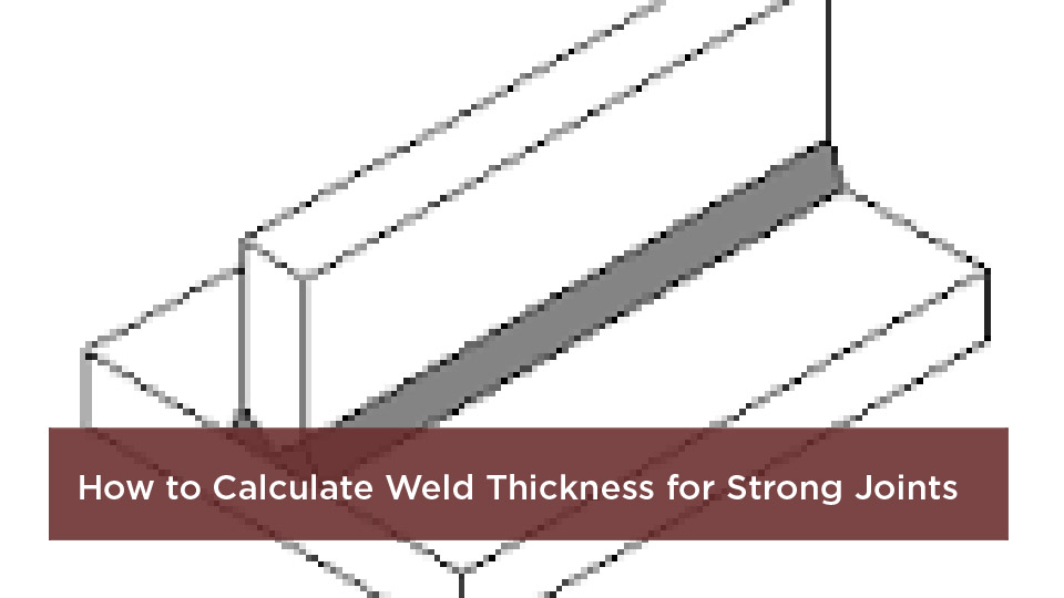
Photo by mitcalc
Warning: The simplified formulas below are educational examples for direct loading. Building connections, lifting devices, vehicle chassis, pressure vessels or piping, seismic systems, fatigue-critical equipment, and other life-safety work require the governing code, complete load analysis, an approved design, a qualified welding procedure, qualified personnel, and the required inspection.
Why Calculating Weld Thickness Is Crucial in Welding Projects
A weld should be large enough to transmit the required force without being needlessly oversized. An undersized weld can lack the required effective throat or length. An unnecessarily large weld increases filler use, arc time, heat input, shrinkage, and the chance of distortion without automatically improving the connected parts.
The required size comes from the load path and the governing design rules. The welding process then has to produce that size with acceptable fusion, profile, toughness, and soundness. That distinction matters: a design calculation does not replace a Welding Procedure Specification, and a good-looking bead does not prove that the specified throat or penetration was achieved.
This guide uses the basic weld-strength framework in ANSI/AISC 360-22 for structural steel examples. Fabrication, procedure qualification, welder qualification, workmanship, and inspection for common carbon and low-alloy structural steels may also be governed by AWS D1.1/D1.1M:2025 and the project documents.
The load calculation gives the required weld capacity. The code, joint detail, base metal, WPS, and inspection plan decide whether that calculated weld is permitted and buildable.
Understanding the Basics: What Is Weld Thickness?
“Weld thickness” is a common search term, but it is not precise enough for a drawing or calculation. Depending on the joint, the reader may be referring to the fillet leg, effective throat, effective length, deposited weld cross-section, groove depth, or complete penetration through the joint.
| Term | Meaning | Why It Matters |
|---|---|---|
| Fillet leg size, w | Distance from the weld root to a toe, measured along the connected surface | Usually the dimension shown beside a fillet-weld symbol |
| Effective throat, te | The shortest effective load path through the weld cross-section, as defined by the governing rules | Used with effective length to calculate weld area and strength |
| Effective length, L | The weld length permitted to resist the applied load | Short, discontinuous, end-loaded, or poorly distributed welds may need special treatment |
| Effective weld area, Awe | Effective throat multiplied by effective length | This is the area used in the basic weld-metal strength equation |
| Groove-weld effective throat | The effective penetration established by the groove detail and applicable code | It cannot be assumed from the visible cap alone |
Leg Length vs. Effective Throat: What’s the Difference?
For an equal-leg fillet in a 90-degree joint, the theoretical weld cross-section is treated as a right isosceles triangle. The effective throat is:
te = 0.707w
A 1/4-inch equal-leg fillet therefore has a theoretical throat of:
0.707 × 0.250 in. = 0.177 in.
The 0.707 relationship is not a universal rule for every joint angle or unequal-leg weld. For an unequal-leg fillet in a 90-degree joint with leg dimensions a and b and a straight face between the toes, the geometric throat is:
te = ab ÷ √(a² + b²)
Use the joint detail and governing code rather than replacing that relationship with a rule based only on the shorter leg.
Note: A fillet-weld gauge can check leg size and compare the face with permitted convex or concave profiles. It does not directly reveal hidden root fusion or internal penetration. Demonstrating extra root penetration normally requires an approved procedure and the evidence required by the governing code.
How to Calculate Fillet Weld Thickness
Fillet-weld sizing begins with the force that must cross the joint. For more detail on the strength side of the calculation, see this guide to calculating fillet weld strength. The method below covers a simple equal-leg fillet carrying concentric direct load. It does not cover an eccentric bracket, a weld group under moment, prying, torsion, fatigue, or seismic demand.
Products Worth Considering

7piece Fillet Weld Set Gage Rl Gauge

12piece Fillet Weld Set Gage Rl Gauge

Durable: Made of high-quality 304 stainless steel, this gauge set has great rust resistance and wear resistance.
Information You Need Before Calculating
- Governing design and welding documents: the adopted code edition, drawings, specifications, and WPS.
- Design method: LRFD factored load or ASD service-level load.
- Applied forces: shear, tension, compression, moment, torsion, fatigue range, and load direction.
- Joint geometry: one or two weld lines, effective length, joint angle, edge distance, and access.
- Filler classification: the specified
FEXX, such as 70 ksi for an E70 classification. - Base-metal information: specification, thickness, tensile strength, yield strength, weldability, and any toughness requirements.
- Fabrication controls: process, position, preheat, interpass temperature, root opening, backing, sequence, and inspection.
Core Fillet-Weld Formulas
For an equal-leg fillet in a 90-degree joint:
Effective throat: te = 0.707w
Effective weld area: Awe = 0.707wL
For the basic conservative weld-metal check without a directional strength increase:
Nominal weld strength: Rn = 0.60FEXXAwe
For LRFD:
Design strength = φRn, where φ = 0.75
wrequired = Pu ÷ (0.75 × 0.60FEXX × 0.707L)
For ASD:
Allowable strength = Rn ÷ Ω, where Ω = 2.00
wrequired = 2.00Pa ÷ (0.60FEXX × 0.707L)
Use pounds with inches and psi, or kips with inches and ksi. Do not mix units. AISC includes angle-dependent provisions for some fillet-weld loading conditions, but those provisions have application limits and should not be added blindly to a basic hand calculation.
Step-by-Step Fillet-Weld Example
Assume a simple T-joint with these conditions:
- One continuous 10-inch fillet weld
- Equal-leg fillet in a 90-degree joint
- 4,000 lb concentric service-level shear
- ASD method
- E70 filler, so
FEXX = 70,000 psi - Thinner connected part is 3/8 inch thick
- No directional strength increase
- No fatigue, eccentricity, moment, torsion, seismic demand, or special toughness requirement
- Calculate the ASD allowable weld-metal stress.
(0.60 × 70,000 psi) ÷ 2.00 = 21,000 psi - Calculate the required effective throat.
te = 4,000 lb ÷ (21,000 psi × 10 in.) = 0.0190 in. - Convert throat to equal-leg fillet size.
w = 0.0190 in. ÷ 0.707 = 0.0269 in. - Apply the code minimum. The calculated 0.0269-inch leg is far below the applicable AISC minimum. For a 3/8-inch thinner connected part, the table minimum is a 3/16-inch leg.
- Check the selected weld’s basic ASD capacity.
Rallowable = 21,000 psi × 0.707 × 0.1875 in. × 10 in. = approximately 27,800 lb - Complete the remaining checks. Verify the base metal, connected elements, effective length, edge limit, load distribution, fit-up, WPS, and inspection requirements.
For this limited example, the 3/16-inch minimum governs rather than the direct-load strength calculation. That does not mean every 3/8-inch joint should receive a 3/16-inch weld; the actual loads, code, joint, and fabrication requirements still control.
Minimum Sizes Based on Material Thickness
The following table summarizes the minimum fillet leg sizes in AISC 360-22 Table J2.4. It uses the thickness of the thinner part joined. It is a design minimum, not proof that the weld has adequate strength for the applied load.
| Thickness of Thinner Part Joined | Minimum Fillet Leg Size |
|---|---|
| Up to 1/4 in. inclusive (up to 6 mm) | 1/8 in. (3 mm) |
| Over 1/4 through 1/2 in. (over 6 through 13 mm) | 3/16 in. (5 mm) |
| Over 1/2 through 3/4 in. (over 13 through 19 mm) | 1/4 in. (6 mm) |
| Over 3/4 in. (over 19 mm) | 5/16 in. (8 mm) |
Check the adopted AWS code and project specification as well. Fabrication rules may impose an additional minimum or other restriction based on material, loading category, joint type, process, or application.
Maximum Size and Effective-Length Checks
Minimum size is only one boundary. The maximum permitted fillet along the edge of a connected part also matters. As explained in the AISC fillet-weld engineering FAQ:
- For material less than 1/4 inch thick, an edge fillet generally should not exceed the material thickness.
- For material 1/4 inch thick or thicker, the edge fillet generally should not exceed the material thickness minus 1/16 inch, unless the applicable full-thickness exception and verification requirements are satisfied.
- A fillet weld designed on strength should have enough effective length. Under the AISC short-weld rule, a length below four times the nominal weld size limits the effective size that can be credited.
- Long end-loaded welds, intermittent welds, returns, HSS connections, and weld groups can have additional effective-length or load-distribution provisions.
See this separate guide for more detail on the maximum fillet weld size for plate thickness.
Pro Tip: When a direct-load calculation produces a very small required weld, do not stop at the formula. Minimum weld size, minimum effective length, edge geometry, access, distortion, and the connected material often control the detail.
When the Load Is Not Simple Direct Shear
A bracket, tab, base plate, lifting lug, tube connection, or frame joint often places the weld group under more than one force. The weld may resist direct shear plus an eccentric moment, torsion, tension, or out-of-plane bending.
For these cases, calculate the demand throughout the weld group rather than dividing the total load by total weld length. The critical point may be at a corner or at the point farthest from the weld-group centroid. The design must also consider whether both sides of a double-sided weld can share the force as assumed.
Do not apply a universal “vertical,” “horizontal,” or “20% cyclic” multiplier. For fatigue, use the governing stress-range, cycle, and detail-category provisions. Increasing weld size alone can fail to improve a fatigue-sensitive detail and may increase restraint or residual stress.
Determining Groove Weld Thickness
Groove welds are used where the joint needs controlled penetration into prepared edges. The effective throat comes from the groove type, joint preparation, root condition, backing, welding process, position, and the applicable code—not from the visible reinforcement above the plate surface.
Complete vs. Partial Penetration: When to Choose Each
| Groove Type | Effective Throat | Typical Design Considerations |
|---|---|---|
| CJP | Generally the thickness of the thinner part joined for the applicable CJP detail | May be selected where full penetration and the specified load path are required; can require backing, back gouging, access from two sides, qualified procedures, and volumetric inspection |
| PJP | The effective throat specified for the qualified or prequalified joint detail | Can reduce weld volume and distortion when full penetration is unnecessary, but its available strength must be calculated from the credited throat |
A CJP weld should not be described as automatically “100% efficient.” With matching-strength filler and common loading, the connected base metal may govern, but the joint still requires the applicable base-metal, connection, procedure, toughness, and inspection checks.
A PJP weld likewise has no universal 80% or 90% efficiency. Its strength is based on the effective throat permitted by the joint detail and governing code. The unpenetrated root and the resulting stress concentration also matter for fatigue and fracture-sensitive applications.
Choose CJP or PJP during design, not after welding. The drawing and WPS should define the groove angle, root opening, root face, backing, access, effective throat, process, position, and inspection requirements.
Key Factors That Influence Weld Sizing
Load Types and Directions
Begin with the complete load path. A weld can be subjected to:
- Direct shear parallel or transverse to the weld axis
- Tension or compression normal to the connected surface
- Eccentric moment
- Torsion
- Out-of-plane bending or prying
- Repeated stress range and fatigue
- Impact, seismic, thermal, or dynamic load
The governing demand may occur at only one point in a weld group. When loads act in several directions, calculate the combined resultant using an accepted weld-group method. Do not assume that simply increasing the leg size compensates for an incorrect load path or flexible connected plate.
Material Properties and Compatibility
Filler classification, base-metal strength, weldability, toughness, and heat-affected-zone behavior must all be considered. A stronger plate does not automatically require a larger weld, and a higher-strength filler does not automatically create a stronger connection. The required load and the weakest applicable limit state govern.
Do not use a carbon-steel sizing rule and then add an arbitrary percentage for another alloy. AWS publishes separate structural welding codes and standards for different materials and applications. Its codes and standards directory includes structural steel, aluminum, sheet steel, stainless steel, and other specialized work.
Pressure vessels and many pressure-piping systems are outside ordinary AWS D1.1 structural-steel scope. They require the applicable construction code and procedure-qualification rules, such as the relevant edition of the ASME Boiler and Pressure Vessel Code or piping code.
Base-Metal and Connected-Part Strength
A weld calculation is incomplete until the connected material is checked. Depending on the joint, possible limit states include:
- Gross-section yielding
- Net-section rupture
- Shear yielding or shear rupture
- Block shear
- Tear-out or edge failure
- Local bending of a plate, angle, tube wall, or bracket
- Lamellar tearing or through-thickness strain
- Buckling or crippling of a thin connected element
An oversized weld can transfer enough force to damage a thin plate or tube wall before the weld reaches its own calculated capacity.
Practical Tips for Accurate Weld Calculations
Prep Work and Joint Design
Remove oil, moisture, paint, rust, scale, plating, and other contamination as required by the WPS and safety controls. Do not assume that adding weld metal will compensate for a poor fit.
For fillet-welded joints, bring the parts into the fit-up permitted by the governing code. The AISC fillet-weld FAQ summarizes AWS provisions under which a root opening up to 1/16 inch may be accepted without modification in the referenced condition. Larger permitted openings generally require increasing the weld size by the opening, demonstrating that the required throat was achieved, or using another approved correction.
Groove angles, root faces, root openings, and backing dimensions should match the approved detail. A narrow groove may restrict access or fusion, while an unnecessarily wide groove increases weld volume, heat, shrinkage, and cost.
Preheat and Interpass Temperature
There is no universal rule such as “150°F for one-inch plate.” Preheat depends on the governing code, base-metal group, thickness, carbon equivalence, hydrogen level, heat input, restraint, ambient temperature, and procedure.
Use the required WPS and the applicable code table or calculation. The manufacturer’s discussion of welding preheat explains why temperature selection must be tied to the material and application rather than a single thickness shortcut.
Machine Settings for Optimal Welds
Voltage, amperage, wire-feed speed, travel speed, electrode diameter, polarity, shielding gas, transfer mode, and technique are procedure variables—not weld-design formulas. A setting that produces a 3/16-inch fillet with one wire diameter and position may produce a different profile with another machine, gas, joint, or travel speed.
Start with the approved WPS or the consumable and equipment manufacturer’s parameter range. Confirm the result on representative material when permitted, then measure the bead and complete any required procedure testing or inspection. Do not rely on a universal “amps per thousandth” rule for SMAW, GMAW, FCAW, or GTAW.
Measuring and Inspecting the Finished Weld
Visual inspection should confirm the specified length, leg size, profile, continuity, termination, and visible workmanship criteria. A suitable gauge can help check fillet leg dimensions, concavity, convexity, undercut, and reinforcement where applicable.
Visual measurement cannot prove every internal condition. Depending on the joint and project, inspection may also include magnetic-particle, dye-penetrant, ultrasonic, radiographic, macroetch, or other approved examination. The specified inspection method must suit the discontinuity and joint being evaluated.
Note: If a weld is undersized, do not grind away the entire weld automatically. The governing acceptance criteria may allow a limited local underrun, or the deficient area may be corrected by an approved added weld. Unnecessary removal can introduce distortion, gouging, or cracking.
Common Mistakes When Calculating Weld Thickness and How to Avoid Them
- Using leg size as the load-bearing area: Convert the leg to effective throat and multiply by the permitted effective length.
- Mixing ASD and LRFD: Do not apply an ASD safety factor to an LRFD factored load or vice versa.
- Treating FEXX as yield strength: It is the filler-metal tensile classification used in the weld-strength provisions.
- Applying 0.707 to every fillet: The common formula assumes an equal-leg fillet in a 90-degree joint.
- Counting convexity as extra design throat: Use the effective throat permitted by the code and joint detail.
- Ignoring minimum and maximum size rules: A strength calculation alone may produce a weld that is not permitted or practical.
- Using total physical length without checking effectiveness: Short welds, long end-loaded welds, returns, and eccentric weld groups can require reductions or separate analysis.
- Adding an informal safety factor: Use the governing load combinations and either LRFD or ASD factors.
- Ignoring the base metal: The plate, angle, tube wall, or bracket may fail before the weld.
- Using blanket fatigue percentages: Evaluate stress range, cycles, detail category, geometry, and inspection requirements.
- Choosing settings from plate thickness alone: Follow the WPS and manufacturer ranges for the actual process, consumable, position, gas, and joint.
- Assuming a clean face proves penetration: Internal fusion and groove penetration may require qualified procedures and nondestructive examination.
Weld Thickness Across Welding Processes
The required design size does not change merely because the process changes. MIG, TIG, stick, flux-cored, and submerged-arc welding can have different deposition rates, access needs, penetration characteristics, position limits, and qualification requirements, but each process must produce the specified weld under an acceptable WPS.
| Process | Useful Characteristics | Sizing and Procedure Caution |
|---|---|---|
| GMAW / MIG | High productivity and easy automation in controlled conditions | Transfer mode, gas, wire diameter, position, and wind protection affect fusion and bead shape |
| GTAW / TIG | Precise control and clean weld deposits for suitable applications | Lower deposition rate can make large structural welds inefficient; procedure and shielding remain critical |
| SMAW / Stick | Portable and widely used for field structural work | Electrode classification, diameter, storage, hydrogen control, position, slag removal, and pass sequence matter |
| FCAW | High deposition rates and common structural applications | Wire classification, shielding method, position, heat input, and manufacturer limits must match the WPS |
| SAW | Very high deposition for suitable shop joints and long seams | Usually limited by position and access; heat input, flux, electrode combinations, and procedure qualification are important |
There is no reliable “ideal thickness range” that applies to every machine and joint. A small GMAW machine, a spray-transfer production setup, and an automated system may all be called MIG equipment while having very different capabilities.
Using Tools and Software for Weld Calculations
A calculator or spreadsheet can reduce arithmetic errors, but it cannot choose the governing load case or code provision for you. A useful calculation sheet should show:
- Code and edition
- ASD or LRFD method
- Load combinations and units
- Weld layout and effective length
- Filler classification
- Required throat and leg size
- Minimum and maximum size checks
- Short-weld, long-weld, or weld-group provisions
- Base-metal and connected-element checks
- Fatigue, seismic, toughness, or special-service requirements
- Selected WPS and inspection requirements
Finite-element or CAD software can help with complex stress distribution, but it still depends on correct loads, restraints, mesh, material behavior, weld representation, and code interpretation. Treat software output as a calculation to verify, not automatic approval.
For field inspection, keep the drawing, WPS, suitable weld gauges, measuring tools, lighting, and acceptance criteria available. Record the actual weld location and deficiency instead of relying on memory or a photograph without scale.
Products Worth Considering
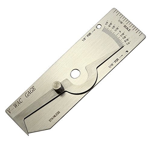
V-WAC Single Weld Gage

· Made of excellent material ☞ made of stainless steel, with a smooth surface through wire drawing process, thickened design, sufficient materials, not easy to rust, not easy to bend or deform, and long service life.

V-Wac Welding Gauge
Wrapping It Up: Your Path to Confident Weld Sizing
To calculate weld thickness correctly, start with the load and the joint—not the welding process. Define the governing code and design method, calculate the required effective throat and length, convert the throat to the correct weld dimension, and then apply all minimum, maximum, fatigue, base-metal, procedure, and inspection rules.
For a standard equal-leg 90-degree fillet, te = 0.707w is the key geometry relationship. It is only the start of the design. A reliable joint also needs a buildable detail, compatible filler and base metal, controlled fit-up, an approved WPS, a qualified welder or operator, and inspection suited to the consequences of failure.
Frequently Asked Questions
What is the effective throat of a fillet weld?
The effective throat is the effective load-carrying distance through the weld cross-section. For a standard equal-leg fillet in a 90-degree joint, it is normally calculated as 0.707 times the leg size. Other joint angles, unequal legs, flare grooves, and credited root penetration require the applicable geometric and code rules.
How do AWS and AISC requirements affect minimum weld thickness?
AISC 360 provides structural design requirements, including weld strength and design-size limits. AWS D1.1 provides welding requirements for covered carbon and low-alloy structural steels, including fabrication, qualification, workmanship, and inspection provisions. The project may adopt both, along with more restrictive drawing or specification requirements.
What is the minimum fillet weld size for 1/2-inch steel?
Under AISC 360-22 Table J2.4, a 3/16-inch minimum fillet leg applies when the 1/2-inch material is the thinner part joined. The weld must also be large enough for the calculated force and satisfy the governing AWS code, loading category, WPS, edge-size, effective-length, and project requirements.
Can I use the same weld-thickness calculation for aluminum and steel?
The geometric 0.707 relationship still describes an equal-leg fillet in a 90-degree joint, but the allowable or design strength, filler selection, heat-affected-zone behavior, procedure qualification, and code requirements differ. Structural aluminum should be designed and welded under the applicable aluminum rules rather than by adding a fixed percentage to a steel weld.
How does joint preparation affect the required weld size?
Joint preparation affects access, fusion, effective throat, penetration, weld volume, and distortion. It should not be corrected with an arbitrary 10% or 20% size increase. If a root opening exceeds the amount permitted without modification, follow the code-approved correction, such as increasing the specified size, demonstrating the required throat, using suitable backing, or repairing the fit-up.
Can a fillet weld be too large?
Yes. A weld can violate an edge-size limit, interfere with fit or service, create an unacceptable profile, or add unnecessary heat, shrinkage, distortion, labor, and filler. However, an inadvertently oversized fillet is not automatically rejectable if its profile is acceptable and it does not interfere with the member’s use. Follow the governing acceptance criteria before removing it.
Can a weld gauge confirm complete penetration?
No. A surface gauge can check visible dimensions and profile, but it cannot prove hidden root fusion or complete penetration. CJP verification relies on the approved joint detail, qualified or prequalified procedure, fit-up control, process execution, and any required nondestructive examination.
Sources
- AISC 360 — Specification for Structural Steel Buildings — structural-steel weld design, strength methods, and current specification information
- AWS D1.1/D1.1M:2025 Release — current structural welding code for covered carbon and low-alloy constructional steels
- AISC Engineering FAQ 8.3: Fillet Welds — oversized and undersized welds, edge limits, fit-up, and termination guidance
- American Welding Society Codes and Standards — material- and application-specific welding standards
- OSHA 29 CFR 1910.252 — welding, cutting, ventilation, PPE, confined-space, coating, and general safety requirements
- 2025 ASME Boiler and Pressure Vessel Code — current code information for boilers, pressure vessels, and related pressure-equipment work