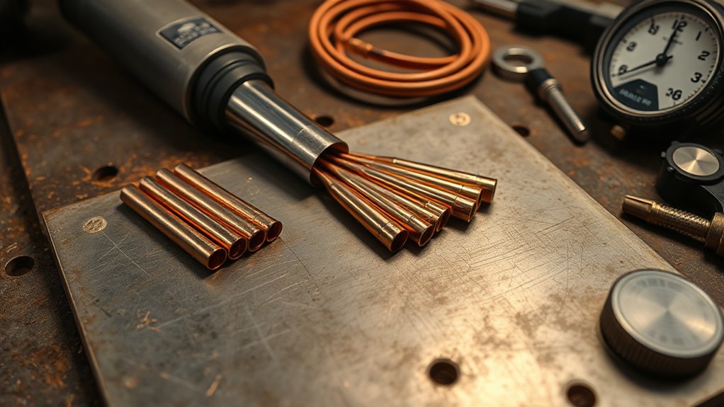
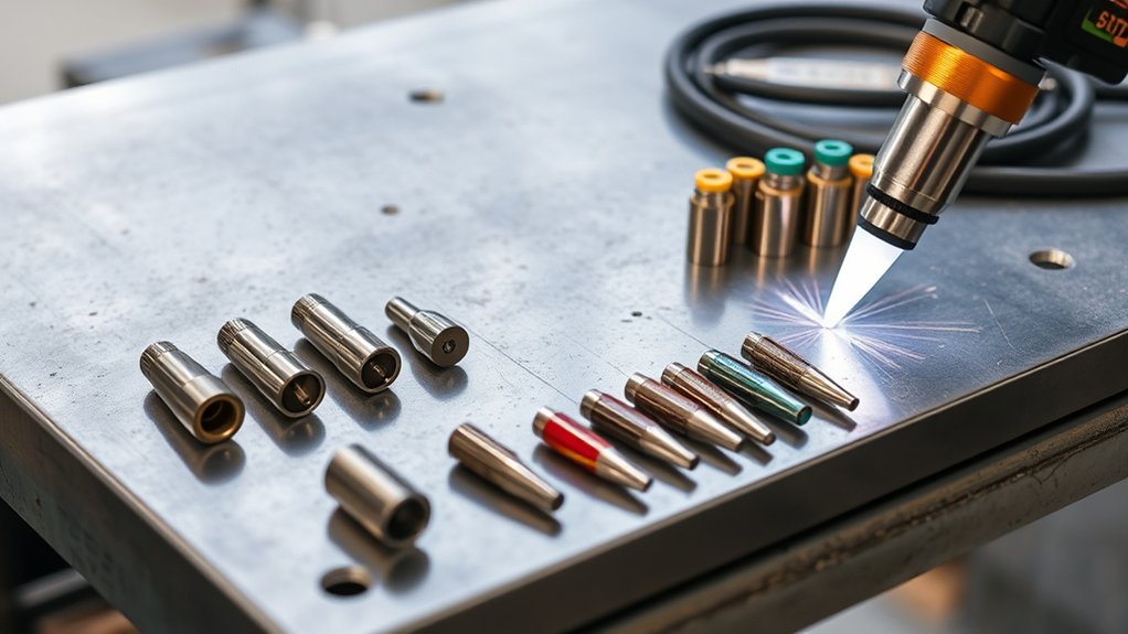
Measure twice, cut once—tip size isn’t guesswork, it’s driven by amperage. You need to match the nozzle orifice to your current to control arc density, kerf width, and edge quality. A 0.6 mm tip at 15–20 A handles thin sheet perfectly, while a 1.1 mm tip at 51–60 A is built for thicker stock. If you don’t pair the nozzle’s amp rating to your machine’s output, you will burn through consumables and ruin your cut accuracy. Once that match is set, you can dial in your standoff, pierce height, gas flow, and speed.
Quick Answer: Matching Tips to Amps
For the best cut quality and longest consumable life, match your tip size to your amperage setting. Using a tip rated for higher amps than you are running causes an unstable arc; using a tip rated for lower amps will blow out the nozzle.
- 15–20 Amps (0.6 mm / 0.025″): Best for thin sheet metal (26 gauge to 1/8″).
- 30–40 Amps (0.9 mm / 0.035″): The standard range for 1/8″ to 3/8″ steel.
- 50–60 Amps (1.1 mm / 0.044″): Required for heavy plate (1/2″ and up).
- Rule of Thumb: Set your machine to the maximum amperage rating of the tip you are using.
Why Your Owner’s Manual Is Your First Stop
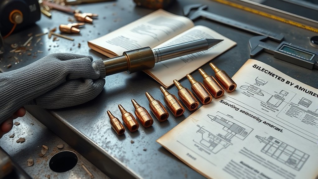
Before you start tweaking settings or swapping consumables, open your plasma cutter’s owner’s manual. It contains model-specific safety specs, input power requirements, and critical cues that prevent costly mistakes.
Start with the manufacturer’s prescribed parameters: initial pierce height, pierce delay, cut speed, and arc voltage. These baseline values align with the machine’s control logic and torch design to yield accurate kerf, stable arc transfer, and consistent edge quality.
Start with prescribed pierce height, delay, speed, and arc voltage for stable, precise, consistent cuts.
Use the cut charts to match material type and thickness to the correct consumable set and amperage. This guarantees that the nozzle orifice is compatible with the gas dynamics and thermal load.
Deviate from these specs only after you’ve established a clean reference cut. Once you have a baseline, you can fine-tune for coatings, alloys, or specific surface conditions.
Leverage the manual’s troubleshooting tips when you see bevel, dross, double arcing, or premature nozzle wear. You can usually isolate causes—like incorrect stand-off, excessive speed, wrong amperage, or contaminated air—very quickly.
Consistent manual use tightens your process window, protects the torch, and maximizes consumable life and cut performance.
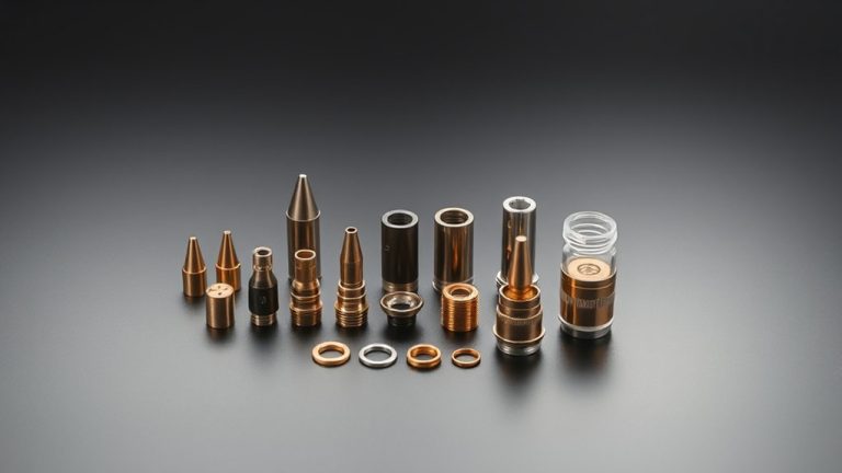
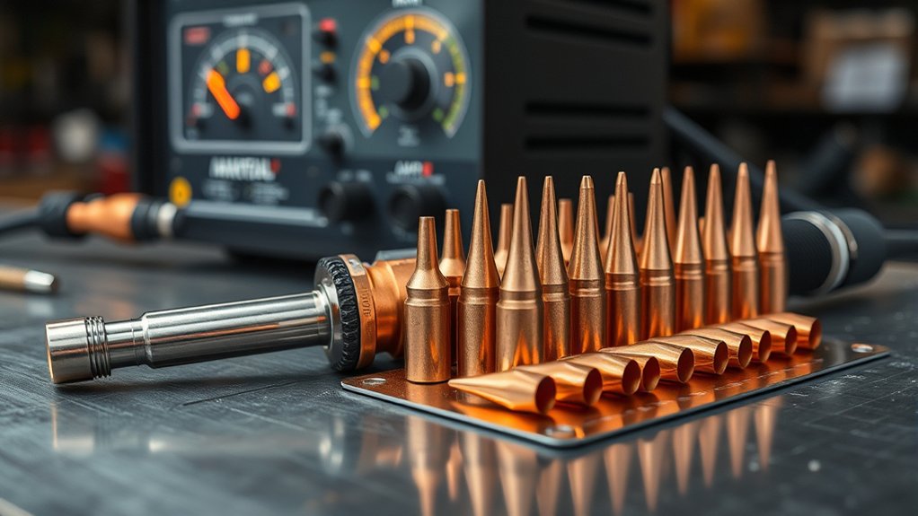
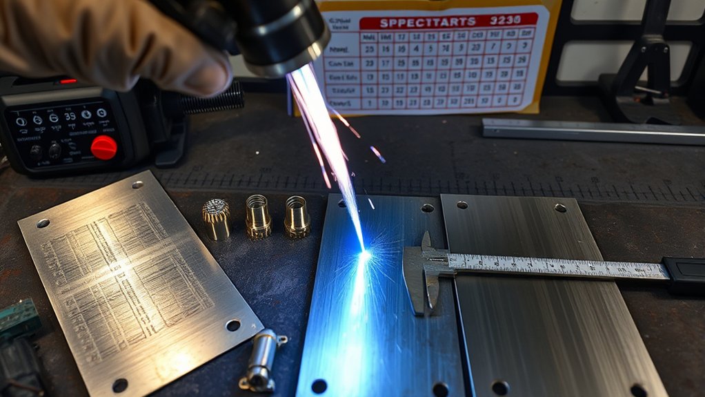
Tip Size to Amperage Selection Chart
Next, map the tip orifice to amperage. This matches arc stability with material thickness and duty cycle.
Reference a selection chart (typically 0.6–1.1 mm tips spanning 15–60 A) and align air pressure to keep the plasma plume coherent. As amperage and tip size increase, expect kerf width to grow. Note the acceptable kerf ranges to control part tolerance and heat input.
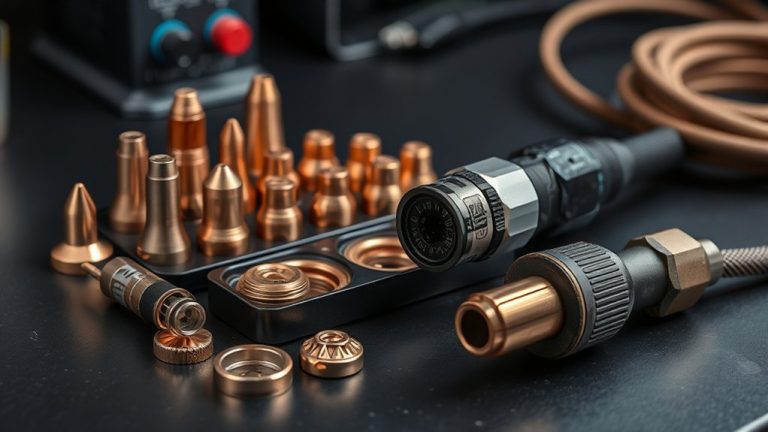
Products Worth Considering

Item Package Quantity: The package contains 20pcs S25/S45 plasma cutting consumables electrode PD0110 & PD0116-08 tips/nozzles


compatible with MicroCut 600 Plasma Cutter,with Forney 251,replacement Forney 85392,produce made by Theia Technical
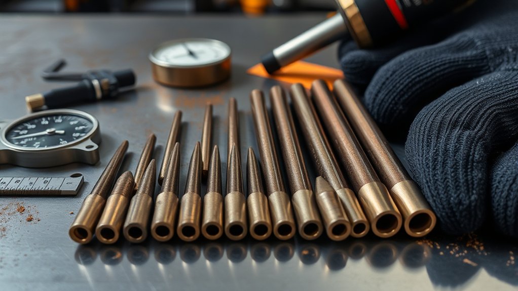
Tip Size vs. Amps
Although plasma systems vary by brand, the tip orifice diameter always dictates the amperage window you should run for clean kerfs and stable arcs.
Match the tip size to your output current to stabilize plume density and maintain arc constriction. If you undershoot (low amps on a big tip), you’ll get arc wander. If you overshoot (high amps on a small tip), you’ll erode the orifice instantly. See these consumable optimization guidelines for more detail.
Here are the practical amperage effects:
- 0.6 mm (0.025 in): 15–20 A. Ideal for thin stock, controlled travel, and minimal dross.
- 0.8 mm (0.030 in): 21–30 A. Great for mild-steel mids, offering balanced cut quality and speed.
- 0.9 mm (0.035 in): 31–40 A. Used for thicker sections requiring a robust arc column.
- 1.0 mm (0.040 in): 41–50 A. Accurate on materials up to 1/4 inch.
- 1.1 mm (0.044 in): 51–60 A. For heavy work, higher feed rates, and deeper penetration.
Set your gas, standoff, and travel speed to the chosen window.
Kerf Width Ranges
Kerf control starts with matching tip orifice to amperage. The cut width will track just above the nozzle diameter and broaden as current and heat input rise.
You’ll see kerf width expand as you step up tip size and amps, and contract when you reduce both. For a 0.6 mm (0.025 in) tip at 15–20 A, expect a tight kerf suited to thin stock and high cutting precision.
A 0.9 mm (0.035 in) tip at 31–40 A widens the kerf for faster removal on thicker plate. Maintain ideal travel speed—slower feeds inflate the kerf and degrade edge fidelity.
Apply these load rules: Use ~20 A for the first 1/8 inch of thickness, add +10 A per additional 1/8 inch, and then select the matching orifice.
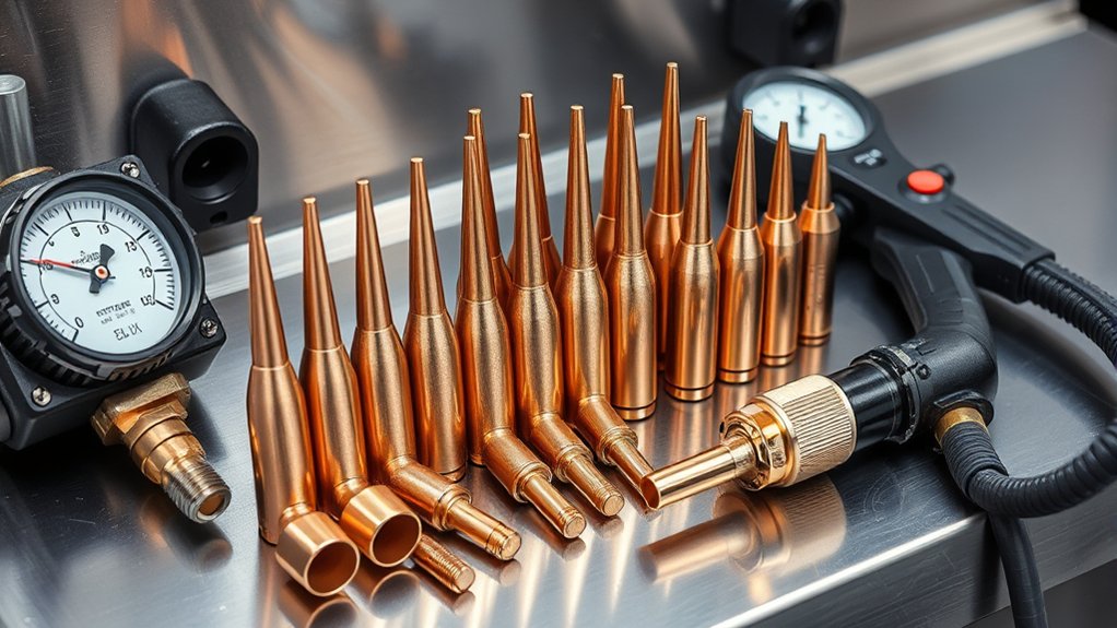
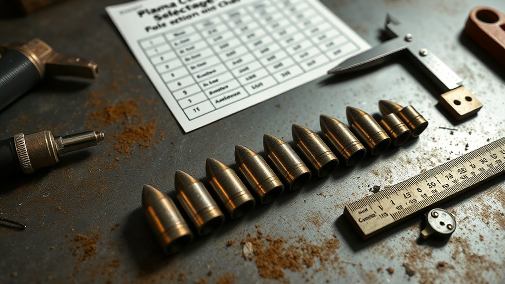
Matching Nozzle Rating to Machine Amps
Before you strike an arc, match the nozzle’s orifice to your machine’s output so the plasma stream stays stable and efficient. Treat tip selection as a spec-driven process: verify nozzle compatibility with your amperage setpoint and material gauge.
Use orifice diameter as your guide. A 0.6 mm tip pairs with 15–20 A; a 1.0 mm orifice suits about 20 A; a 1.3 mm nozzle is rated for 71–80 A.
Undersizing the nozzle at higher current overheats the orifice, distorts the jet, and accelerates consumable wear. Oversizing at low amps yields a lazy arc, wider kerf, and dross. For thin stock and precision features, choose smaller tips—0.6 mm around 20 A or 0.8 mm near 30 A. Step up orifice size as thickness and amperage climb.
Lock in gas delivery: maintain 65–75 psi unless your OEM chart specifies otherwise. Correct matching delivers crisp edges, minimal dross, and longer nozzle life.
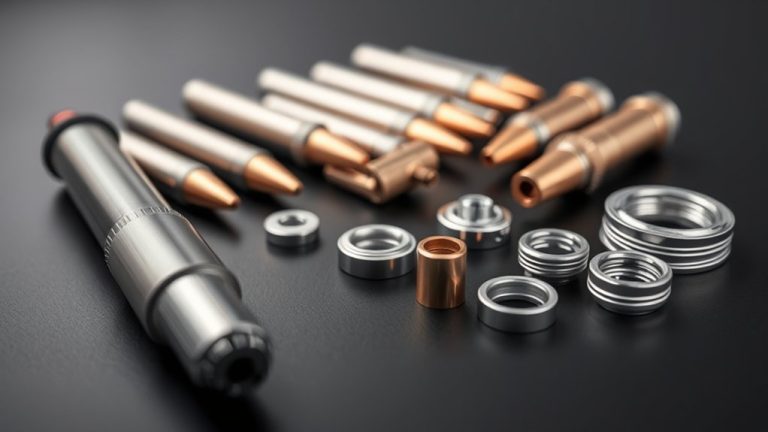
Products Worth Considering

10 pcs TIPS (Extended) /10 pcs ELECTRODE (Extended) /10 pcs SHIEDED-CUP/10 pcs GAS RING

[Achieve Precise Cuts] PT31 Plasma Cutting Consumables – Your Essential Tool for Efficient Cutting! Whether you're working with sheet metal, steel, or any other material, superior cutting performance ensure clean, accurate, and smooth cuts.

High-Quality Material:Made of high quality material to ensure a longer lifespan and superior performance.
Cut Height, Pierce Height, and Arc Voltage Essentials
Dialing in cut height, pierce height, and arc voltage is non-negotiable for clean cuts and consumable life. Set cut height per the operator’s manual and hold it within ±0.005 inches. That tolerance controls angularity, kerf consistency, and heat input, preventing warpage.
Use a reliable torch height control (THC) and verify standoff with feeler gauges or calibration routines.
For pierce height, run 1.5–2.0 times the torch-to-work distance. That clearance vents molten metal (ejecta) away from the torch, protecting the nozzle and shield while ensuring a clean pierce. After the pierce delay, shift to the prescribed cut height before motion begins.
Arc voltage is essentially your tool for measuring standoff distance. Adjust voltage to track the correct cut height across varying plate conditions. Increase voltage slightly if you’re dragging; decrease it if you’re riding too high. Tune by material type and thickness, then lock parameters in your program.
Monitor, log, and adjust. Following the manual’s cut height and pierce height specs maximizes consumable lifespan and repeatable cut quality.
Gas and Coolant Flow Requirements by Tip Size
Although amperage sets your heat input, tip size dictates gas and coolant demand to keep the arc stable and consumables alive. Match gas pressure and flow to the orifice: 20 A tips typically run 50–55 psi; 40 A tips prefer 65–70 psi; 50–60 A tips need increased flow, often in the 65–75 psi band, to maintain jet velocity and dross control.
Verify torch-side pressure under flow (dynamic pressure), compensating for hose length, filters, and regulators.
Larger tips dump more heat into the torch. If your system is liquid-cooled, prioritize coolant maintenance: confirm reservoir level, mix ratio, and pump output. Monitor return temperature and flow indicators; insufficient cooling accelerates nozzle and electrode erosion.
For 60 A operation, watch for rising outlet temperature, reduced flow, or steam cavitation—signs you’re overheating. Set interlocks so low-flow faults stop the arc. Keep heat exchangers clean, purge air from the loop, and service filters.
Gas pressure plus reliable coolant flow preserves cut quality and extends consumable life.
Consumable Types: Standard, Shielded, and Drag Tips
You’ll choose between standard tips for balanced speed/quality, shielded tips for precision and extended life, and drag tips for stable, surface-contact tracing.
Match orifice size to amperage—smaller bore, lower amps—to control kerf width and cut quality.
Select based on material thickness and application: general cutting (standard), fine detail and nozzle protection (shielded), or hand-guided, intricate paths with torch-on-metal contact (drag).
Standard Tips Overview
Three common plasma cutting tip styles—standard, shielded, and drag—cover most shop scenarios and material thicknesses. Here’s where you focus: standard tip benefits and a quick performance comparison.
Use standard tips for day-to-day work because they’re versatile across steels, aluminum, and stainless at varied thicknesses. They deliver consistent kerf, stable arc initiation, and predictable dross levels when matched to amperage.
Select the nozzle orifice to suit your amperage and material. Smaller orifices concentrate arc velocity and temperature but demand lower amperage; larger orifices carry higher amperage for thicker stock. For clean cuts, pair the orifice with proper travel speed and standoff.
Compared with drag tips, standard tips prefer a controlled standoff (a gap between the torch and metal), offering better edge definition on plate. Choose based on cut quality targets and efficiency requirements.
Shielded Tip Benefits
A shielded tip adds a protective cap that stabilizes the plasma column, isolates the nozzle from arc blow, and resists atmospheric disruption—key for thicker plate and outdoor work.
You’ll see tighter kerf geometry, fewer arc outages, and higher cutting efficiency when wind or mill scale would otherwise disturb the jet.
Shielded tips also block spatter from impacting the nozzle face, preserving orifice integrity and maintaining consistent arc constriction.
That means cleaner edges, reduced dross, and longer consumable intervals. The cap absorbs radiant and convective heat, extending tip life versus standard designs and lowering operating cost per foot.
Match shielded tips to your torch model, amperage range, and gas mix per the manufacturer’s spec. Proper fit-up, standoff, and amperage pairing guarantee stable arcs, predictable wear, and repeatable cut quality.
Drag Tip Usage
For many handheld jobs on thin sheet, drag tips let the torch ride directly on the workpiece, locking the standoff distance and stabilizing the arc for narrow kerf and crisp edges. You gain drag tip advantages: simplified torch control, consistent height, tighter kerf, and improved cut quality on light-gauge stock. Use them primarily on thin materials; for thicker plate, step up amperage and consider shielded or standard tips.
Match amperage to material and tip rating to prevent nozzle washout, double-arcing, and premature wear. Keep travel speed steady; avoid lingering at pierce to protect the orifice. Prioritize drag tip maintenance: inspect orifice roundness, dross buildup, and heat discoloration; replace when the hole eggs out or cuts widen.
| Selector | Guidance |
|---|---|
| Material | Thin sheet, light plate |
| Amperage | Tip-rated, low-to-mid |
| Kerf | Narrow, clean |
| Technique | Direct contact, steady feed |
| Maintenance | Inspect, clean, replace promptly |
Kerf Width and Speed Guidelines for Thin to Thick Metals
Although plasma kerf varies by consumable and machine, you can control it by matching tip size, amperage, and travel speed to material thickness.
Manage kerf width and cutting speed as a linked pair: slower travel widens the kerf; faster travel narrows it. Because kerf is slightly larger than the orifice, select a tip whose nozzle diameter suits the metal’s thickness, then set amperage and speed accordingly.
Treat kerf and speed as linked: match tip size to thickness, then set amps and travel accordingly.
As a rule of thumb, expect kerf to be approximately 1.5× the orifice diameter (e.g., 1.0 mm orifice → ~1.5 mm kerf). On thicker stock, step up tip size and amps, then increase travel speed to prevent overburn and taper.
- Thin gauge (≤1.6 mm): Small orifice, low amps, high speed for minimal kerf.
- 3–6 mm: Medium orifice, moderate amps, maintain steady, brisk speed.
- 6–12 mm: Larger orifice, higher amps, increase speed to hold kerf.
- >12 mm: Largest recommended tip, high amps, optimize speed to avoid dross.
- Always tune speed via test coupons; validate edge quality, slot width, and taper.
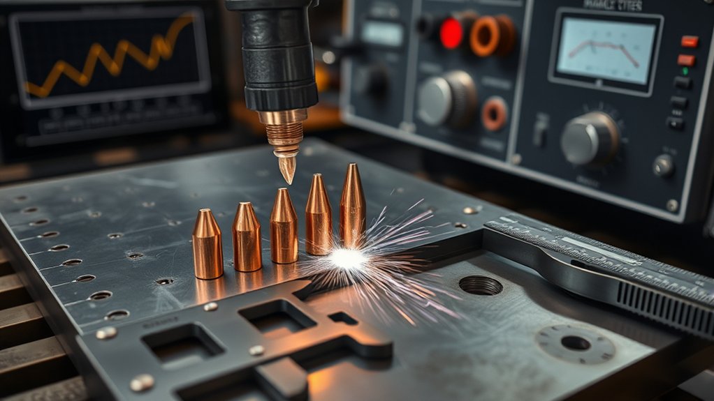
Wear Indicators and Replacement Pit Depths
When consumables start to drift out of spec, you’ll see clear wear signals. You must act before cut quality collapses. Build a rapid wear assessment routine: inspect nozzle orifice diameter, electrode pit depth, color changes, and edge results. Enlarged orifices, brown/blue discoloration, and rising dross are primary flags that cut geometry and arc stability are degrading.
Measure electrode pits with a depth gauge. Replace standard all-copper electrodes at 0.040 inches depth. Replace silver/hafnium-interface electrodes at 0.080 inches. Exceeding these limits accelerates arc wander, taper, and kerf growth, undermining consumable longevity and amperage-specific tip selection.
Track duty metrics: pierce starts are a practical trigger—around 40 pierces per nozzle is a common changeout interval. Verify nozzle seating and concentric alignment; poor fit multiplies erosion at the orifice entrance.
Monitor coolant flow and gas delivery pressures to keep thermal load stable. Document findings, hours, pierces, and pit depths; adjust replacement cadence to your amperage, material thickness, and cut schedule.
Common Causes of Premature Consumable Failure
You’ll shorten consumable life fast if you mismatch amperage to the tip rating—overcurrent scorches nozzles, while undercurrent leaves dross and unstable arcs.
Verify your setpoint against the nozzle’s max amperage and actual cut load to maintain proper energy density.
Poor gas flow—low pressure, restrictions, or contamination—starves the arc. Monitor supply, inspect filters/lines, and perform leak checks to prevent rapid wear.
Incorrect Amperage Matching
Even slight mismatches between set amperage and the nozzle’s rated capacity accelerate consumable wear and degrade cut quality. Amperage misalignment overheats the orifice, distorts the jet, and shortens consumable longevity.
Running above the nozzle’s max burns the nozzle face, erodes the cathode spot, and destabilizes arc geometry. Running too low causes dross, shallow penetration, and longer arc-on time, compounding wear.
Pair tip size to output current, then hold travel speed and standoff to maintain arc stability.
- Verify nozzle rating vs. programmed amps; never exceed nameplate limits.
- Adjust output to match material thickness, not “one-setting-fits-all.”
- Monitor cut edge coloration and kerf taper as early overload indicators.
- Standardize torch height and traverse speed to avoid thermal cycling.
- Log amperage, tip size, and life data to optimize settings.
Poor Gas Flow
Although arc current and standoff matter, poor gas flow destroys consumables fastest by starving the arc of cooling and shielding. Low supply elevates arc temperature, accelerates nozzle erosion, and destabilizes kerf.
Validate gas pressure at the torch inlet—most systems run 65–75 psi under flow. Don’t trust static readings; perform flow measurement with the torch purging to confirm actual delivery.
Inspect for restrictions: clogged filters, oil/water contamination, crushed hoses, tight bends, or partially closed valves. Check quick-connects and fittings for leaks; soap-test under pressure.
Straighten kinks, replace compromised lines, and purge moisture from the air system.
Schedule routine verification: log flow rates, compare to OEM specs, and correct deviations immediately.
Maintaining consistent gas pressure and verified flow prevents premature consumable failure and preserves cut quality.
Brand Variability and How to Dial In Settings on Your Machine
Because plasma cutters don’t output amperage equally across brands, start by anchoring your setup to the manufacturer’s cut chart and then verify on your machine. Brand differences mean a nominal 40 A on a premium Hypertherm may track closer to spec than a budget imported unit.
Anchor your setup to the cut chart, then verify on your machine—brand amperage varies.
Use the chart to select the correct tip size and amperage, then dial in precise settings with test cuts, watching kerf, dross, and bevel.
Match the nozzle orifice to current. Don’t run a 0.6 mm tip beyond 20 A—overheating erodes the orifice and degrades arc stability. As thickness increases, bump current roughly +10 A per additional 1/8 inch after the first.
Validate with arc start quality, cut speed, and edge metallurgy.
- Verify output with a clamp meter; confirm command vs delivered amps.
- Keep tip within its rated amperage band to prevent double-arcing.
- Tune travel speed to extinguish trailing dross.
- Adjust standoff height for minimal bevel.
- Re-test when switching alloys or thicknesses; document final settings.
Frequently Asked Questions
How Does Ambient Temperature Affect Plasma Tip Life and Performance?
Ambient temperature directly impacts plasma tip longevity and performance. You’ll see faster erosion in high heat, and moisture-induced arc instability in the cold. Manage cooling, preheat your workspace, ensure a dry air supply, and maintain duty cycle to stabilize wear.
Are Aftermarket Tips Compatible With CNC Torch Height Control Systems?
Yes, if the geometry and electrical specs match OEM. Verify aftermarket compatibility, including orifice size, stand-off, gas flow, and electrode composition. Calibrate your torch height control: arc-voltage setpoint, kerf compensation, and pierce delay. Run a test cut, log arc-voltage stability, and adjust THC hysteresis and sampling rate.
What Tip Sizes Work Best for Cutting Expanded Metal or Grating?
Like threading needles through a mesh, you’ll favor small orifices. For expanded metal/grating, use tip sizes between 0.8–1.0 mm (40–60 A). Match the metal thickness, use fine-cut nozzles, higher standoff, lower amperage, increased travel speed, and “mesh-cut mode” if your machine has it.
How Do Water Tables Influence Tip Cooling and Cut Quality?
They cool the nozzle indirectly, stabilizing arc temperature and reducing tip erosion. You gain water table benefits: splash-back suppression, fume capture, and reduced distortion. Cut quality generally improves with narrower kerf, smoother edges, less dross, fewer microcracks, and better dimensional repeatability.
Can I Use the Same Tip for Gouging and Cutting Operations?
No—you shouldn’t. Cutting and gouging tips differ in orifice geometry, gas flow, and amperage range. Mixing them reduces tip compatibility, arc stability, and gouging efficiency. Use manufacturer-specific gouging consumables; match nozzle, shield, and current to the process.
Conclusion
You’ve got the chart, now trust your instruments. Match tip orifice to amperage like you match gearing to torque—0.6 mm at 15–20 A for razor kerfs, and 1.1 mm at 51–60 A for deep, stable cuts. Set cut height, pierce height, and arc voltage; verify gas and coolant flow. Watch kerf, speed, and pit depth wear carefully. When consumables fail early, troubleshoot gas purity, standoff, and duty cycle. Brands vary—dial in your machine, run test coupons, and then let the arc sing on spec.