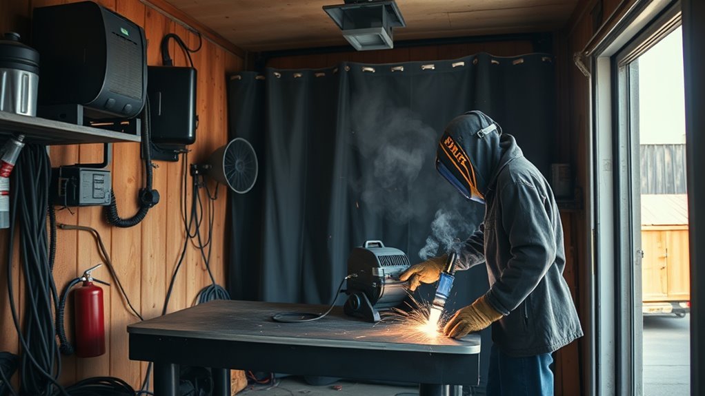
Choosing the best MIG wire for auto body work starts with identifying the metal, checking the vehicle maker’s repair procedure, and matching the wire to your welder. ER70S-6 solid wire works for many mild-steel repairs, but it is not automatically correct for every structural panel, high-strength steel, stainless part, or aluminum component.
Quick Answer
For most mild-steel auto body repairs, use .023- or .030-inch ER70S-6 solid wire with C25 shielding gas, which is 75% argon and 25% CO₂. Use .023 wire for the thinnest panels and .030 when the machine and joint need more output. Follow the OEM procedure for structural steel, stainless, or aluminum.
Key Takeaways
- ER70S-6 is the usual starting choice for many mild-steel collision and patch-panel repairs.
- Use ER70S-3 only when the vehicle maker or an approved welding procedure specifies it.
- Choose .023 or .024 wire for strong low-end control on thin panels; .030 wire covers a wider range when the machine runs it smoothly.
- Select stainless and aluminum wire by the exact base alloy, transfer mode, and OEM procedure.
- Flux-core wire does not make it safe to weld over rust, paint, oil, undercoating, or seam sealer.
- Make and test sample welds before welding the vehicle.
What’s in This Article
- What MIG Wire Works Best for Auto Body?
- Check the OEM Repair Procedure First
- Use ER70S-6 for Mild-Steel Repairs
- Use ER70S-3 Only When Specified
- Pick the Right Wire Size for Sheet Metal
- Why .023 and .030 Wire Work Well on Body Panels
- What Wire to Use for Stainless and Aluminum
- Use Flux-Cored Wire Only When Approved
- Match Your Wire, Gas, and Settings
- Prepare the Vehicle and Work Area
- Make and Test Sample Welds
- Avoid Common MIG Wire Mistakes
- Frequently Asked Questions
- Sources
What MIG Wire Works Best for Auto Body?
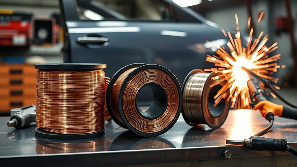
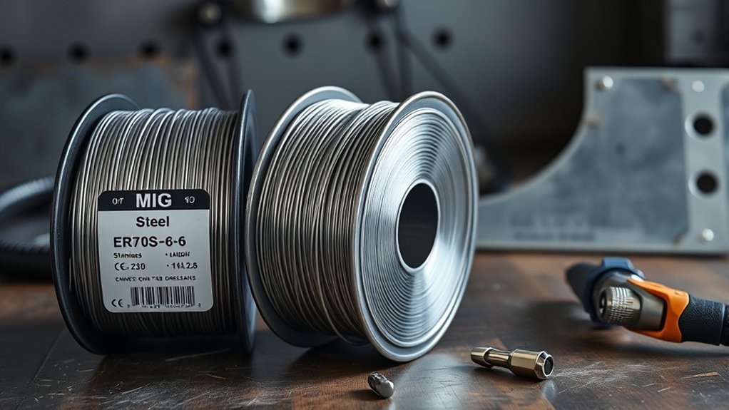
For many mild-steel body panels and collision-repair welds, ER70S-6 solid wire is the best general starting point. It contains more manganese and silicon deoxidizers than ER70S-3, wets into the joint well, and is recommended by I-CAR for most steel collision-repair applications.
The best diameter is usually .023 or .024 inch for very thin sheet and .030 inch for a wider range of sheet-metal and light fabrication work. The correct choice still depends on your machine’s output, the joint design, access, welding position, panel thickness, and the vehicle maker’s instructions.
| Base Metal or Repair | Common Wire | Typical Gas | Important Limitation |
| Mild-steel body panel | ER70S-6, usually .023/.024 or .030 inch | 75% argon and 25% CO₂ | Confirm the machine chart and control heat with spaced welds. |
| Structural or high-strength steel | Only the wire and process named by the OEM | OEM- or wire-specified gas | Conventional GMA welding may be restricted or prohibited. |
| 304 or 304L stainless steel | ER308L or ER308LSi | Tri-mix for many short-circuit applications; argon-rich gas for approved spray or pulsed setups | Match the gas to the wire data sheet and transfer mode. |
| Aluminum | ER4043 or ER5356 when compatible with the base alloy | Usually 100% argon | Use the OEM procedure and an aluminum-capable feed system. |
| Self-shielded flux-core repair | The exact classification approved for the application | No external gas when the wire is self-shielded | More heat, slag, smoke, and spatter; not a substitute for clean metal. |
A self-shielded product such as YESWELDER flux-core MIG wire may suit outdoor utility fabrication, but that does not make it the preferred choice for visible or safety-critical auto body work.
Products Worth Considering
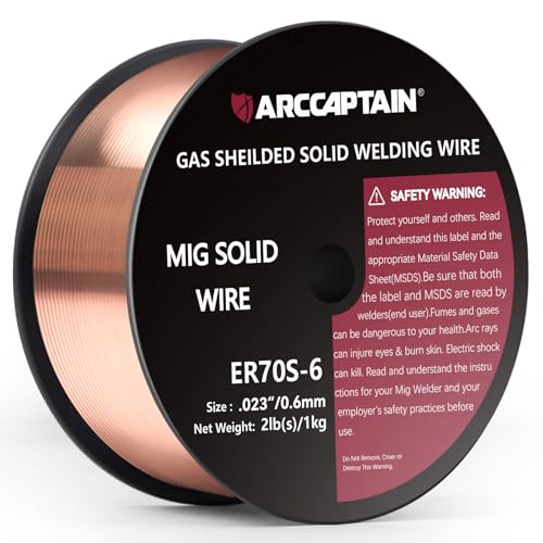
High-quality: ARCCAPTAIN's ER70S-6 mig welding wire .023" meets industry standards(Net Weight: 2lbs), ensuring consistent performance, superior strength. With its smooth feeding and stable welding parameters, you can achieve optimal penetration, high deposition rates, and exceptional overall welding performance.

ER70S-6 PERFORMANCE: This .023 MIG welding wire supports precise arc control and low spatter for single-pass and multi-pass welding.

ER70S-6 MIG WIRE: It's the most common wire of the copper-coated mild steel GMAW (MIG) wires for single or multiple pass welding.
Check the OEM Repair Procedure First
Before you select a spool, identify the vehicle, panel, base material, strength grade, factory coating, and required attachment method. Late-model vehicles may combine mild steel, high-strength steel, ultra-high-strength steel, stainless steel, aluminum, adhesives, rivets, resistance spot welds, GMA welds, and MIG-brazed joints.
I-CAR’s OEM Technical Information Matrix shows why material identification and vehicle-specific attachment instructions matter. A wire that works on an exterior patch panel may be wrong for a rail, pillar, frame section, reinforcement, or crash-management component.
Note: This wire guide helps with selection and setup, but it does not replace the current OEM body repair manual. When the OEM specifies a wire, weld type, plug-weld size, heat limit, adhesive, rivet, spot-weld procedure, or MIG-brazing process, follow that procedure.
Do not assume that ER70S-6 is approved simply because the part is steel. Some vehicle makers limit conventional GMA welding on higher-strength steels or require a different electrode for a specific strength range. I-CAR’s attachment-method guidance gives examples of manufacturer-specific wire restrictions.
Use ER70S-6 for Mild-Steel Repairs
ER70S-6 is the usual all-around choice for low-carbon steel body panels when the OEM permits conventional GMA welding. Its higher deoxidizer content helps the puddle wet into the joint and gives it more tolerance for minor mill scale or residual surface oxidation than ER70S-3.
That tolerance does not remove the need for preparation. Clean away paint, corrosion, oil, dirt, seam sealer, undercoating, and adhesive from the weld zone and from any hidden surface that heat could reach. Review proper metal preparation before you set the final voltage and wire speed.
For short-circuit welding on thin mild steel, C25 gas provides a stable arc with less spatter and less heat than straight CO₂ in many sheet-metal applications. Miller also recommends an argon-rich blend such as 75% argon and 25% CO₂ for sheet-metal welding.
Run ER70S-6 on direct current electrode positive, or DCEP, unless the equipment and wire manufacturer states otherwise. Install the contact tip, drive-roll groove, and liner size that match the wire diameter.
Products Worth Considering

High-quality:Tooliom's .023" ER70S-6 MIG Welding Wire (10lb spool) meets all industry standards for consistent strength and performance. Enjoy smooth feeding, stable arcs, optimal penetration, and high deposition rates—everything you need for exceptional welds

Commonly used for general shop applications with poor fit-up

High Quality & Reliable Welds: VEVOR 0.03" 10 lbs ER70S-6 solid MIG welding wire contains higher levels of manganese and silicon deoxidizers, delivering strong, consistent welds on mild carbon steel—even when working with oily or lightly rusted steel
Use ER70S-3 Only When Specified
Do not choose ER70S-3 simply because you expect a softer arc or a more cosmetic bead. ER70S-3 contains fewer deoxidizers than ER70S-6 and is intended for clean steel under suitable procedures.
Some vehicle makers have specified ER70S-3 for particular frame or structural operations. In those cases, the procedure controls the choice. If the repair manual calls for ER70S-3, use the required diameter, gas, joint design, and machine settings and complete the required test welds before touching the vehicle.
- Use ER70S-3 only on clean steel and under an approved procedure.
- Do not substitute ER70S-6 merely because it is already loaded in the machine.
- Do not substitute ER70S-3 for ER70S-6 when the procedure names ER70S-6.
- Confirm the wire’s AWS classification on the spool label rather than relying on package color or brand name.
If you are learning how filler classifications differ, this overview of common welding filler types can help, but the vehicle repair manual remains the controlling source.
Pick the Right Wire Size for Sheet Metal
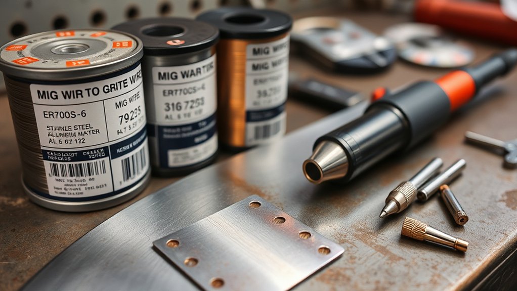
Wire diameter affects the usable amperage range, feed stability, deposition rate, and how easily you can keep a small puddle on thin steel. Smaller wire does not automatically prevent distortion, but it lets many machines operate more smoothly at the lower output needed for thin panels.
| Steel Thickness | Useful Starting Wire | Selection Notes |
| Very thin panels, commonly around 24 to 22 gauge | .023 or .024 inch | Usually gives the best low-end control. Verify that your machine, liner, contact tip, and drive roll support it. |
| Common body sheet, often around 20 to 18 gauge | .023/.024 or .030 inch | Either size may work. Use the one your machine feeds smoothly at the required low output. |
| Heavier sheet and brackets, often around 16 to 14 gauge | .030 inch is common | .035 may be appropriate when the welder, joint, and procedure call for more output. |
| Frame or structural sections | Procedure-specific | Do not select .035 or .045 wire from thickness alone. Follow the OEM procedure and machine requirements. |
An E71T-GS wire may be sold for no-gas utility welding, but it should not replace solid ER70S-6 on a visible or structural body repair unless the procedure permits that exact flux-core classification.
Pro Tip: Keep both .023/.024 and .030 contact tips available. A worn or oversized tip can make the arc wander and imitate a voltage or wire-speed problem.
Why .023 and .030 Wire Work Well on Body Panels
.023- and .030-inch wire cover most of the low-to-moderate output range used for body panels. According to Miller’s wire-size guidance, .023 wire operates in a lower amperage range than larger diameters, while .030 wire overlaps that range and extends farther upward.
- .023 or .024 wire: Best when you need a small, controllable puddle and your machine feeds thin wire reliably.
- .030 wire: A versatile choice for shops that move between body sheet, brackets, and somewhat thicker material.
- .035 wire: Better suited to higher output and thicker stock than most cosmetic patch panels.
Do not compensate for a poor panel gap by installing larger wire and increasing heat. Correct the fit-up first. Maintain a consistent gap when the repair procedure requires one, clamp the panel securely, and keep both pieces aligned.
Use the chart inside your welder as the starting point, then fine-tune the arc on matching scrap. This guide to MIG wire speed and voltage can help you understand the relationship, but the machine chart and successful test weld should determine the final settings.
What Wire to Use for Stainless and Aluminum
Stainless Steel Wire
For common 304 or 304L stainless steel, ER308L or ER308LSi is commonly compatible. ER308LSi contains additional silicon that can improve puddle fluidity and bead wetting. For 316 or 316L stainless, use a compatible 316-series filler unless the approved procedure says otherwise.
Shielding gas depends on the transfer mode:
- For many low-current, short-circuit stainless applications, use the helium-rich tri-mix recommended by the wire or equipment manufacturer.
- For approved spray or pulsed-spray transfer, an argon-rich blend with a small amount of oxygen or CO₂ may be specified.
- Do not assume that 98% argon and 2% CO₂ is the correct gas for every thin stainless panel.
Use clean stainless-only brushes, abrasives, and tools to avoid embedding carbon-steel particles. These 304 stainless welding practices provide additional preparation guidance.
Aluminum Wire
Choose ER4043 or ER5356 only after identifying the aluminum alloy and checking the OEM procedure. ESAB’s comparison of 4043 and 5356 explains that the two fillers differ in strength, ductility, feedability, anodized color, crack sensitivity, and service-temperature limits.
- ER4043: Softer wire with good wetting and relatively low crack sensitivity on compatible alloys.
- ER5356: Stiffer and easier to feed through some systems, with higher shear strength on compatible alloys and better anodized color matching.
Use 100% argon unless the equipment, wire manufacturer, or repair procedure specifies another gas. Aluminum wire normally requires a spool gun or push-pull feeder, a suitable liner, U-groove drive rolls, and aluminum-compatible contact tips. Remove the oxide layer with a clean stainless brush reserved for aluminum.
Do not confuse solid ER4043 or ER5356 wire with products marketed as no-gas aluminum solutions. Review the limitations discussed in this guide to flux-core aluminum products before attempting a repair.
Use Flux-Cored Wire Only When Approved
Flux-cored wire can be useful in selected applications, but it is not the preferred answer for rusty, painted, oily, or poorly prepared body panels. Clean the joint to the standard required by the repair procedure regardless of the wire type.
I-CAR notes that flux-core wire may be specified by some vehicle makers for particular operations. It also produces more spatter and slag than solid wire and is generally unsuitable for very thin body steel unless the OEM approves it.
- Use flux-core only when the vehicle maker or an approved procedure allows it.
- Confirm the exact wire classification, diameter, polarity, and gas requirement.
- Remove all slag before adding another pass, dressing the weld, or applying corrosion protection.
- Provide adequate ventilation because flux-core welding produces substantial smoke and fume.
- Do not use deeper penetration as a reason to weld through corrosion or contamination.
A product such as Forney self-shielded flux-core wire may work for compatible utility fabrication, but product reviews do not establish approval for a collision repair.
Warning: Never weld over paint, fuel residue, oil, undercoating, seam sealer, adhesive, foam, or an unknown coating. Heat can release toxic gases, start a hidden fire, contaminate the weld, and damage nearby vehicle systems.
Match Your Wire, Gas, and Settings
Wire and Metal Match
The filler must match the base metal and the approved repair procedure. Use ER70S-6 for many permitted mild-steel repairs, ER308L or ER308LSi for compatible 304-series stainless, and ER4043 or ER5356 only when compatible with the aluminum alloy.
Do not judge the base metal by color or magnetism alone. Use the OEM material map, repair manual, part markings, and an approved identification method. A coated high-strength panel may look like ordinary mild steel while requiring a different attachment process.
Gas Choice Matters
For mild-steel short-circuit transfer, 75% argon and 25% CO₂ is a common body-shop gas because it gives a smooth arc and lower spatter than straight CO₂. A different argon/CO₂ ratio may also be approved by the wire, machine, or vehicle maker.
Stainless gas must match the transfer mode. Aluminum commonly uses 100% argon. Self-shielded flux-core does not use external gas, while gas-shielded flux-core requires the gas named in its data sheet.
Review this guide to shielding gas for mild steel, then confirm the final choice against the wire manufacturer’s data and the OEM repair information.
Polarity and Wire-Feeding Equipment
Most solid steel, stainless, and aluminum GMA wires run on DCEP, which means the gun is positive and the work lead is negative. Many self-shielded flux-core wires run on DCEN, but this is not universal. Read the spool label and machine manual before changing polarity.
- Match the contact-tip bore to the wire diameter.
- Use the correct drive-roll groove and avoid excessive drive pressure.
- Use a clean, correctly sized liner for steel or stainless wire.
- Use a spool gun or push-pull system when soft aluminum wire will not feed reliably through a conventional gun cable.
- Keep the gun cable as straight as practical while welding.
Settings for Thin Sheet
Begin with the welder manufacturer’s chart for the metal thickness, wire diameter, gas, and joint type. Make adjustments on scrap rather than experimenting on the vehicle.
- Voltage: Controls arc length and strongly affects bead shape and heat.
- Wire-feed speed: Controls current in a constant-voltage MIG system.
- Stickout: Keep it consistent; excessive stickout can make the arc unstable and reduce penetration.
- Travel speed: Moving too slowly overheats the panel, while moving too fast can cause poor tie-in.
- Torch angle: Use a slight push angle when it improves visibility and gas coverage, unless the procedure specifies another technique.
Do not bevel thin exterior body panels unless the repair procedure calls for that joint preparation. A wide bevel removes material and often forces you to add more heat and filler than the panel can tolerate.
Control Heat and Distortion
For a permitted cosmetic patch-panel seam, place short welds or spaced tacks around the repair instead of running one long continuous bead. Move between distant areas so heat does not build in one spot. Allow the panel to cool naturally between sequences.
Do not apply cosmetic patch-panel techniques to a structural joint that requires a continuous seam, plug welds, specified stitch length, resistance spot welds, brazing, or adhesive. Follow the exact joint design in the OEM procedure.
Prepare the Vehicle and Work Area
Welding safety includes more than a helmet and gloves. OSHA lists welding fumes, ultraviolet radiation, burns, electrical shock, and other physical hazards among the risks that must be controlled. Review OSHA’s welding hazard guidance before performing hot work.
- Remove flammable cleaners, rags, fuel residue, trim, insulation, foam, and loose combustibles from both sides of the weld area.
- Inspect enclosed sections, pillars, rocker panels, quarter panels, and floor cavities for seam sealer, sound deadener, wiring, hoses, and factory foam.
- Use local fume extraction or effective ventilation without directing strong air across the shielding-gas envelope.
- Wear an approved welding helmet, safety glasses, gloves, flame-resistant clothing, and respiratory protection when the hazard assessment requires it.
- Protect glass, paint, upholstery, modules, and nearby panels from sparks and grinding debris.
- Keep suitable fire-extinguishing equipment within reach and check hidden areas during and after welding.
I-CAR advises placing the work clamp close to the weld to keep the current path short and protecting vehicle electronics before welding. Follow the vehicle maker’s battery-disconnection and module-protection instructions. On many vehicles, this includes isolating both battery cables in the correct order.
Warning: Hybrid and electric vehicles contain high-voltage systems that require manufacturer-specific shutdown, verification, and personal protective equipment. Do not perform welding near a high-voltage system unless you are trained and authorized for that vehicle.
Make and Test Sample Welds
Before welding the vehicle, make samples with the same metal type, thickness, coating condition, joint design, orientation, wire, gas, and access position. Scrap cut from the removed part can provide a close material match.
I-CAR recommends visually inspecting and destructively testing sample welds before making the final vehicle weld.
- Prepare and clamp the test pieces the same way as the vehicle joint.
- Set the machine from its chart and make the sample weld.
- Check the face for complete fill, consistent shape, cracks, skips, undercut, excessive buildup, and visible porosity.
- Check the back of the sample for the penetration or melt-through required by that joint.
- Break, twist, peel, or bend the sample using the approved test for the weld type.
- Adjust one variable at a time and repeat the test until the sample passes.
- Use the successful settings on the vehicle without changing the wire, gas, polarity, joint, or extension.
Pro Tip: Record the successful wire diameter, voltage, wire-feed speed, gas flow, polarity, stickout, and joint position. That note gives you a repeatable starting point if the repair requires many identical welds.
Troubleshoot Common Test-Weld Problems
- Burn-through: Reduce heat input, shorten weld duration, improve fit-up, or move to smaller wire if your machine supports it.
- Tall, rope-like bead: Check voltage, travel speed, torch angle, surface cleanliness, and whether the wire is tying into both pieces.
- Wire stubbing into the panel: Increase voltage slightly or reduce wire-feed speed after confirming contact-tip and feed condition.
- Arc burning back into the tip: Check wire-feed speed, tip condition, liner drag, and drive-roll tension.
- Porosity: Check for contamination, wind, poor gas flow, leaks, a blocked nozzle, excessive stickout, or an empty cylinder.
- Excessive spatter: Confirm polarity, gas, clean metal, voltage-to-wire-speed balance, and contact-tip condition.
- Panel warping: Shorten each weld, increase spacing between weld locations, allow cooling time, and correct panel tension or fit-up.
Avoid Common MIG Wire Mistakes
Good body welds come from the complete system rather than the wire classification alone. Avoid these common errors:
- Choosing wire before identifying the base metal and OEM attachment method.
- Using ER70S-3 because it is assumed to be softer or easier on thin panels.
- Treating ER5356 as the correct aluminum wire for every alloy.
- Using an argon-rich stainless spray gas with a low-output short-circuit setup without checking the wire data sheet.
- Installing .035 wire because a poor joint gap needs more filler.
- Using flux-core as a shortcut around rust, paint, undercoating, or contamination.
- Running solid wire with flux-core polarity or flux-core wire with solid-wire polarity.
- Leaving the wrong contact tip, liner, or drive roll in the machine after changing wire size.
- Welding the vehicle before making and breaking a test coupon.
- Grinding the completed weld so aggressively that the surrounding sheet becomes thinner.
- Failing to restore weld-through primer, epoxy primer, cavity wax, seam sealer, and other corrosion protection as required by the repair procedure.
After the weld passes inspection, dress it only as much as the repair procedure permits. Clean the area and restore every corrosion-protection layer removed during the repair.
Frequently Asked Questions
What MIG wire is best for auto body welding?
ER70S-6 solid wire is the usual starting choice for permitted mild-steel auto body repairs. Use .023/.024 or .030 inch wire with C25 shielding gas, then verify the wire, diameter, and process in the OEM repair procedure.
Should I use .023 or .030 wire for body panels?
Use .023 or .024 wire when you need the best low-output control on very thin sheet. Use .030 wire when your machine feeds it smoothly and the panel, joint, or bracket requires more output. On 18- to 20-gauge steel, either size may work, so confirm the choice with a test coupon.
Is ER70S-3 better than ER70S-6 for thin sheet metal?
Not as a general rule. ER70S-3 contains fewer deoxidizers and should be used when a vehicle maker or approved procedure specifies it. ER70S-6 is recommended for most conventional steel collision-repair applications, subject to the OEM instructions.
Can I use flux-core wire on an auto body panel?
Only when the wire, metal thickness, equipment, and OEM procedure allow it. Flux-core creates more heat, smoke, slag, and spatter than solid wire and is usually a poor choice for thin visible panels. It does not make welding over rust or paint acceptable.
What shielding gas should I use with ER70S-6?
C25 gas, which contains 75% argon and 25% CO₂, is a common choice for short-circuit welding on mild-steel body panels. It provides a stable arc with less spatter than straight CO₂ in many thin-sheet applications.
What MIG wire should I use for stainless auto parts?
ER308L or ER308LSi is commonly used for compatible 304 or 304L stainless. Use a matching 316-series filler for 316 stainless unless the approved procedure states otherwise. Match the shielding gas to the transfer mode and wire manufacturer’s data.
Is ER4043 or ER5356 better for aluminum body work?
Neither wire is universally better. ER4043 often offers good wetting and lower crack sensitivity on compatible alloys, while ER5356 is stiffer and provides different strength and anodized-color properties. Identify the base alloy and follow the OEM filler recommendation.
Do I need to disconnect the car battery before MIG welding?
Follow the vehicle maker’s welding and battery-isolation procedure. Protect sensitive modules, keep the work clamp close to the weld, and keep the welding-current path away from electronics. Hybrid and EV high-voltage systems require trained shutdown and verification procedures.
Sources
- I-CAR Steel GMA Welding Theory — ER70S wire classifications, polarity, wire-size ranges, vehicle protection, flux-core limits, and test-weld procedures.
- I-CAR: Advanced Vehicles and Collision-Repair Attachment Methods — OEM-specific wire and material restrictions.
- Miller: Successfully Welding Sheet Metal With MIG and TIG — mild-steel shielding gas and stainless filler guidance.
- Miller: Setting the Correct MIG Parameters — wire-diameter operating ranges and setup principles.
- ESAB: Choosing Between 4043 and 5356 Aluminum Filler — aluminum alloy compatibility and filler-selection differences.
- OSHA Welding, Cutting, and Brazing Hazards and Solutions — fumes, radiation, burns, electrical hazards, PPE, and ventilation.