
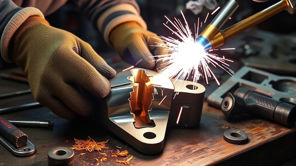
A broken engine or transmission mount needs more than a strong-looking weld. The mount controls powertrain position while absorbing vibration and repeated torque loads. In most vehicles, replacing the damaged mount or bracket is the safest repair. Welding should be considered only for a removable metal bracket when the vehicle maker permits it or a qualified automotive fabricator approves a documented repair.
Quick Answer
Replace a broken engine or transmission mount unless the vehicle maker or a qualified repair professional approves welding the specific removable metal bracket. Never weld the rubber or hydraulic isolator. For an approved repair, support and remove the powertrain component, identify the alloy, prepare and weld the crack to a documented procedure, inspect it, and reinstall it to factory specifications.
Key Takeaways
- Replace a complete rubber, fluid-filled, electronic, cast, or badly distorted mount instead of trying to weld it.
- Support the engine or transmission at the service-manual locations before loosening any mount hardware.
- Weld only a removable bare-metal bracket when the material is known and the repair is permitted.
- Never weld near residue from chlorinated cleaner, fuel, oil, or flammable solvent vapor.
- A smooth bead does not prove internal fusion or fatigue strength; use dimensional checks and appropriate inspection before road use.
At a Glance
| Time Required | Usually several hours; access, powertrain support, removal, inspection, and reassembly often take longer than the weld itself. |
| Difficulty | Advanced or professional; this is not a beginner automotive welding project. |
| Tools Needed | Vehicle support equipment, engine support fixture or approved jack setup, hand tools, torque wrench, grinder, clamps or fixture, suitable welder, PPE, fire protection, and inspection supplies. |
| Cost | Varies by vehicle and damage. Compare the complete cost of professional removal, fabrication, inspection, hardware, and reinstallation with an OEM-quality replacement part. |
Warning: Do not weld a rubber or hydraulic isolator, an unknown casting, a body or subframe attachment, or any mount repair that the vehicle manufacturer prohibits. A failed repair can allow sudden powertrain movement and damage steering, driveline, exhaust, fuel, electrical, or cooling components.
What’s in This Article
- Quick Answer
- Key Takeaways
- At a Glance
- Before You Begin
- Should You Weld or Replace the Mount?
- Why a Secure Mount Matters
- Diagnosing the Damage
- Tools and Materials
- Preparing the Area
- Choosing a Welding Process
- Welding Process
- Inspecting the Repair
- Reassembly and Aftercare
- Troubleshooting
- Frequently Asked Questions
- Safety Disclaimer
- Conclusion
- Sources
Estimated total time: Plan for several hours rather than judging the job by welding time alone. Rusted hardware, limited access, powertrain support, bracket removal, crack inspection, fixture setup, cooling, reinstallation, and final checks can extend the repair.
Before You Begin
First identify what has actually failed. People often use “engine mount” to describe several different parts:
- Rubber or hydraulic isolator: The vibration-absorbing service part between the powertrain and body or subframe.
- Detachable metal bracket: A bolted steel, aluminum, cast-steel, or cast-iron part attached to the engine, transmission, mount, or body.
- Crossmember or subframe attachment: A chassis component that may require an approved structural repair procedure.
- Body mounting point: A welded part of the vehicle structure that should be repaired only under body-repair specifications.
Do not assume all four parts can be treated the same way. A torn rubber isolator, leaking hydraulic mount, electronic active mount, broken casting, elongated bolt hole, or distorted chassis attachment normally calls for replacement or an OEM-approved structural repair.
Obtain the service procedure for the exact year, make, model, engine, transmission, and drivetrain. The procedure should identify support points, removal order, reusable and single-use fasteners, torque values, alignment requirements, battery or module isolation, and any restriction on welding.
Before loosening mount hardware, support the engine or transmission using the service-manual method. An engine support bar, transmission jack, or floor jack with an approved load-spreading adapter may be required. Never rely on the damaged mount to hold the powertrain while you work.
Note: Hybrid and electric vehicles contain high-voltage systems that remain hazardous even when the 12-volt battery is disconnected. High-voltage isolation and verification should be completed only by a trained person following the vehicle maker’s procedure.
Should You Weld or Replace the Mount?
Replacement is the preferred repair for most passenger-vehicle mounts. Welding becomes a reasonable option only when the damaged piece is a removable metal bracket, its material and loading are known, replacement is impractical, and an approved repair can restore the original geometry.
| Condition | Safer Direction |
| Torn, collapsed, oil-soaked, leaking, or separated rubber or hydraulic isolator | Replace the complete mount. |
| Broken electronic or active mount | Replace and complete any required calibration or diagnostic procedure. |
| Missing metal, severe bending, elongated bolt holes, damaged threads, or failure through a mounting face | Replace unless an engineer or approved repair procedure specifies restoration. |
| Unknown cast material or heat-treated aluminum bracket | Replace or send it to a specialist who can identify the material and evaluate weldability. |
| Clean crack in a removable fabricated-steel bracket with known material and intact mounting geometry | A qualified repair may be possible when the OEM permits it and a suitable procedure is available. |
| Damage to a crossmember, subframe, unibody rail, body mount, or welded chassis attachment | Use the manufacturer’s structural or collision-repair procedure. Do not apply a generic bracket-welding method. |
The question is not simply whether the metal can be welded. The repair must also restore the mount’s alignment, load path, heat-affected properties, and resistance to repeated engine torque and vibration.
Why a Secure Mount Matters
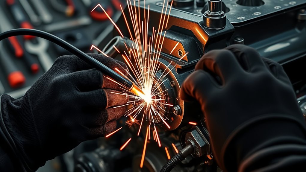
A secure mount keeps the engine or transmission in its designed position while controlling normal movement. Excess motion can load driveshafts, CV joints, shift linkages, wiring, hoses, cooling lines, exhaust joints, intake parts, and nearby brackets.
A stable mount also limits vibration entering the chassis. A broken or misaligned mount may cause clunks during acceleration, braking, startup, shutdown, or gear changes.
A weak mount can allow the powertrain to shift far enough to damage another mount or nearby component. That is why you should inspect the complete mounting system rather than repairing one visible crack and assuming the original failure had no underlying cause.
Some cast components require specialized cast-iron welding techniques, but the presence of a weldable material does not automatically make a loaded engine-mount bracket suitable for repair.
Diagnosing the Damage: Identifying Cracks and Weak Points
Support the vehicle and powertrain safely before applying force or removing hardware. Start with a bright light and inspect the mount, mating surfaces, fasteners, and nearby components.
Look for:
- Visible cracks, torn welds, or broken bracket ears
- Bent tabs, twisted brackets, or surfaces that no longer sit flat
- Elongated bolt holes, damaged threads, loose studs, or missing fasteners
- Collapsed, torn, oil-soaked, separated, or leaking isolator material
- Shiny witness marks showing metal-to-metal contact or unexpected movement
- Cracked paint, fretting, rust trails, or displaced washers near a joint
- Damage to the crossmember, subframe, body attachment, or transmission case
Use only light, controlled leverage if the service procedure permits a movement check. Do not place your hands between the engine, transmission, body, or support equipment. A pry bar can reveal separation, but excessive force can enlarge a crack or shift an inadequately supported powertrain.
Symptoms such as new vibration, clunking, fan or exhaust contact, shifter movement, axle vibration, or excessive engine roll can indicate a failed mount. They can also come from another mount, a damaged bushing, a loose crossmember, an exhaust contact point, or a driveline problem.
Find the Full Crack Before Grinding
Clean enough of the component to see the complete damaged area. Mark both visible ends of the crack before removing metal. If appropriate for the known material, a liquid-penetrant inspection can help reveal surface-breaking cracks that are difficult to see.
Penetrant testing requires correct pre-cleaning, dwell time, excess-penetrant removal, developer application, lighting, and interpretation. It does not reveal every internal flaw and does not prove that a completed weld has full penetration.
Moisture, oil, coating, and residue can also produce weld defects. Similar contamination problems are discussed in this guide to moisture-related flux-core defects.
Warning: Stop if the crack reaches a bolt hole, threaded boss, machined mounting face, thin casting transition, transmission case, engine block, subframe, or body structure. Those conditions need replacement or a component-specific engineered repair.
Key Tools and Materials for Welding Engine and Transmission Mounts
Gather the support, removal, fabrication, fire-control, and inspection equipment before beginning. The exact list depends on the vehicle and approved repair procedure.
- Vehicle service information: Use the exact OEM removal, support, fastener, torque, electrical, and installation instructions.
- Vehicle support equipment: Use a rated lift or jack stands on suitable lifting points, wheel chocks, and the specified engine or transmission support.
- Welder: Use a process with enough capacity and control for the identified material, thickness, joint, and position.
- Compatible filler: Select filler from the approved procedure or reliable base-metal information rather than appearance alone.
- Grinder and abrasives: Use dedicated, uncontaminated abrasives where material compatibility matters.
- Fixture, clamps, and braces: Hold the bracket at its original dimensions without covering the weld zone.
- Measuring tools: Use a straightedge, square, calipers, hole-spacing gauge, or a verified mating component to confirm alignment.
- Cleaning supplies: Use an approved non-chlorinated metal cleaner, clean lint-free rags, and a compatible wire brush.
- Fire protection: Keep a suitable extinguisher nearby and use welding blankets or shields where they provide effective protection.
- Inspection supplies: Use good lighting, magnification, and an appropriate penetrant kit when the material and procedure allow it.
- Safety gear: Wear a welding helmet, safety glasses, gloves, flame-resistant clothing, hearing protection, and suitable respiratory protection when required.
- Torque wrench: Reinstall the mount using the specified fasteners, tightening sequence, and torque values.
Weld size must suit the joint and load path rather than simply looking large. Review the principles of fillet weld sizing, but use the approved repair design for the actual component.
Products Worth Considering
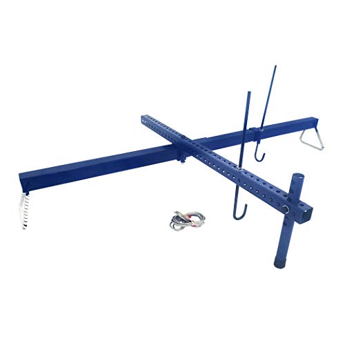
Makes removal of transaxle easy by supporting engine of front wheel drive vehicles

Compatibility: This transverse engine support bar is designed for lifting and supporting nearly all types of car engines, including sports cars, SUVs, sedans, and more
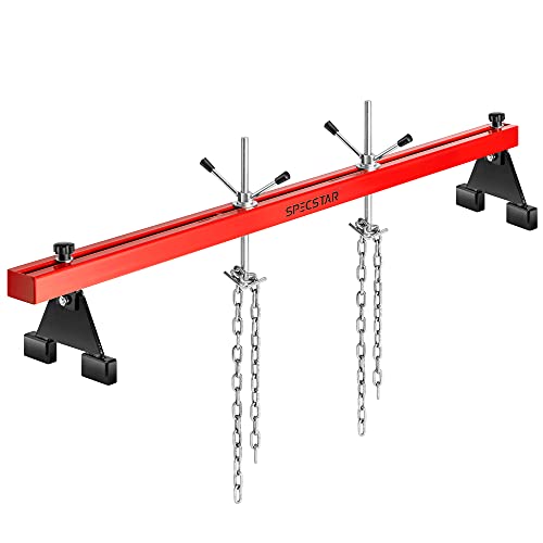
DURABLE AND ROBUST: Constructed with thickened high-strength steel and a double-beam structure, it bears a load of up to 1,100 pounds; The thickened rust-proof coating effectively resists oil contamination and corrosion, ensuring long-lasting use
Preparing the Area: Cleaning and Securing the Mount
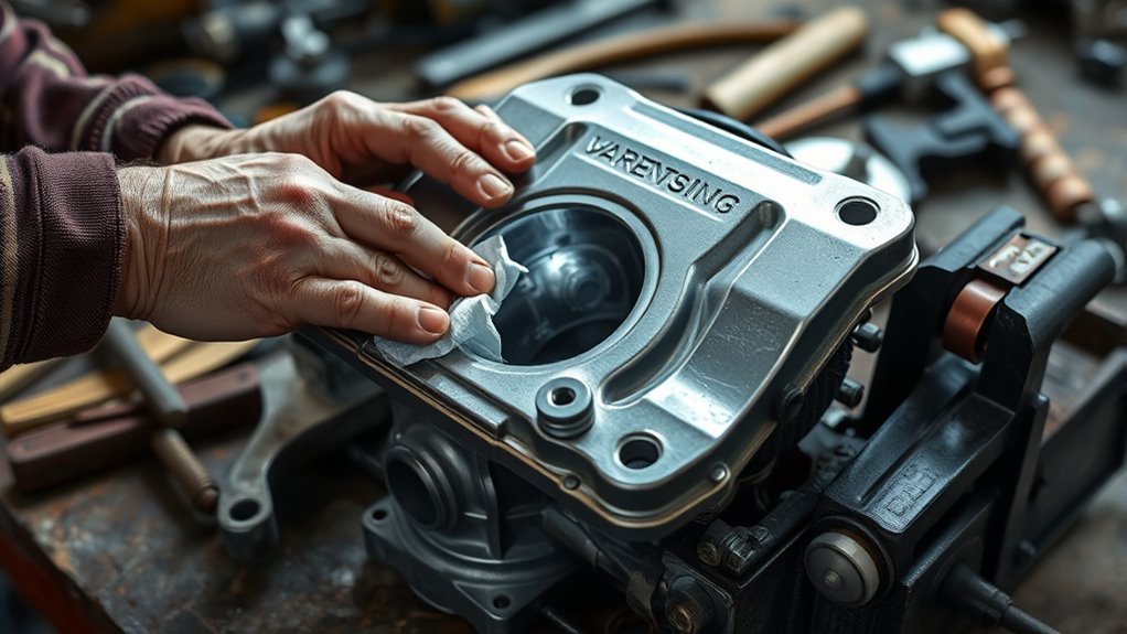
Good preparation controls contamination, alignment, fire risk, and distortion. Whenever practical, remove the bracket and weld it on a bench rather than inside the engine bay or underneath the vehicle.
Support the Powertrain and Remove the Component
- Park and secure the vehicle: Work on a level surface, apply the parking brake, select the specified gear or Park position, and chock the wheels.
- Raise the vehicle correctly: Use the maker’s lifting points and rated support equipment.
- Support the powertrain: Install the specified support fixture or jack before loosening the mount.
- Record the position: Mark adjustable mount or bracket positions when the service procedure calls for it.
- Remove the hardware: Follow the correct order and identify any bolts, nuts, washers, or studs that must be replaced.
- Remove the bracket: Keep the isolator, wiring, hoses, sensors, and other heat-sensitive parts away from the repair.
Do not place a jack beneath an oil pan, transmission pan, cooling component, or aluminum housing unless the manufacturer identifies that location and specifies how the load must be spread.
Assess Damage Thoroughly
- Inspect the complete bracket: Look beyond the visible break for branching cracks, bent sections, worn holes, and damaged mounting faces.
- Confirm material and weldability: Use part information, markings, an approved repair source, or professional identification.
- Map the crack: Mark the full crack path before grinding.
- Check dimensions: Compare hole spacing, mounting angles, faces, and offsets with the mating parts or an undamaged reference.
- Find the cause: Check the other mounts, fasteners, driveline alignment, collision damage, exhaust contact, and abnormal engine movement.
Clean the Mount Correctly
Remove grease and road grime with a cleaner that is approved for welding preparation and confirmed to be non-chlorinated. Read the product label and safety data sheet before use.
Warning: Never weld metal that may retain chlorinated brake cleaner, carb cleaner, degreaser, or another unknown solvent. Chlorinated solvent residue can produce highly toxic decomposition gases around welding heat or ultraviolet radiation. Non-chlorinated cleaners and acetone can still create flammable vapor.
Move cleaner containers and used rags away from the hot-work area. Allow the part, seams, cavities, bench, and surrounding area to dry completely. Ventilate until no solvent vapor remains.
Use a grinder or compatible wire brush to remove paint, rust, scale, undercoating, plating, and old weld material from the repair zone. Clean a wide enough area to inspect the base metal and place the work clamp on bare metal.
Coated or galvanized metal can produce hazardous fumes and requires coating removal and ventilation appropriate to the material. This related guide explains general galvanized-metal cleaning, but welding preparation must also follow hot-work and coating-hazard requirements.
Secure the Components Properly
Fixture the bracket so its bolt holes, mounting faces, angles, and offsets match the original geometry. Do not pull a severely distorted component into position with weld shrinkage and assume the repair has restored its strength.
- Clean the clamp points: Remove contamination that could let the fixture slip.
- Support both sides: Prevent the crack from opening, closing, twisting, or stepping out of plane.
- Check access: Leave room for root preparation, tacks, welding, cleaning, and inspection.
- Verify dimensions: Recheck hole spacing and mounting surfaces before tacking.
- Plan the weld sequence: Use a sequence that limits heat concentration and distortion.
Pro Tip: When possible, bolt the bracket to a rigid fixture or verified spare component during tacking. This is more reliable than judging alignment by eye.
Choosing the Right Welding Technique for Your Mount
The material, joint design, thickness, service load, previous heat treatment, contamination, and access determine whether a repair is weldable and which process is suitable.
Products Worth Considering

RADIATORWELD: Our radiator and plastic tank repair kit has all you need for making professional quality, permanent repairs with state of the art components and easy to follow instructions.

UL CERTIFIED: Our Plastic Welder, the factory, and the process have been tested, approved, and Certified by Underwriters Laboratories (UL). Safety is our number one priority

TANK WELD: Our Metal Fuel tank repair kit has all you need for making professional quality, permanent repairs with state of the art components and easy to follow instructions.
Assess Material Compatibility
A magnet, grinder sparks, color, and casting texture may provide initial clues, but they do not identify an exact alloy. Do not select filler or heat input from those observations alone.
- Fabricated mild-steel bracket: Often the most practical candidate for a documented MIG, TIG, flux-core, or stick repair.
- High-strength or heat-treated steel: May require controlled preheat, filler selection, interpass limits, or replacement.
- Cast steel: Different from cast iron and should be identified before choosing a procedure.
- Cast iron: Crack-sensitive and often contaminated; professional repair or replacement is usually the safer choice.
- Cast or heat-treated aluminum: May lose properties or distort during welding. Unknown aluminum brackets should be replaced or evaluated by a specialist.
- Mixed assembly: Do not weld near bonded rubber, hydraulic chambers, electronics, bushings, bearings, or dissimilar-metal joints without a component-specific procedure.
Select the Appropriate Technique
MIG can provide efficient deposition on many fabricated-steel brackets. TIG provides precise control but does not correct an unsuitable joint design or unknown alloy. Stick or flux-core may be useful for some thicker steel repairs when the approved procedure supports them.
For aluminum, use an aluminum-capable power source, compatible filler, dedicated cleaning tools, and the specified shielding gas. Do not assume every cast-aluminum bracket can be restored safely.
Cast iron may require controlled preheat, suitable nickel or other specified filler, short weld sequences, stress control, and slow cooling. Review established cast-iron welding guidance from Lincoln Electric, then use a professional for a loaded automotive casting.
Follow the welder, consumable, and shielding-gas manufacturer’s data for the selected process. Test settings on verified scrap with the same material and thickness, but do not use a scrap test as a substitute for an approved repair procedure.
Prepare the Joint Before Welding
- Locate the complete crack: Do not grind until both ends and any branches are identified.
- Remove the failed weld or cracked metal: Grind to sound material without unnecessarily thinning the bracket.
- Prepare the groove: Use the groove angle, root opening, backing, and access required by the repair design.
- Clean after grinding: Remove abrasive dust, embedded contamination, and loose particles.
- Fixture the bracket: Confirm all critical dimensions before applying tacks.
- Set heat controls: Establish any required preheat, interpass limit, sequence, and cooling method.
Do not automatically drill the end of a crack, add reinforcement plates, increase weld size, or change the bracket shape. Those changes alter stress flow and should be included only in an approved repair design.
Welding Process: Setup to Execution
For a removable bracket, complete the repair on a clean, fire-safe bench whenever possible. If an approved procedure requires welding on the vehicle, follow the vehicle maker’s welding precautions in addition to normal hot-work controls.
Protect Electronics and Control Fire Risk
- Switch the vehicle off and follow the required shutdown waiting period.
- Disconnect battery cables, modules, alternator circuits, or high-voltage components exactly as the vehicle procedure specifies.
- Place the welding work clamp on clean metal on the part being welded, as close to the arc as practical.
- Do not route welding current through bearings, bushings, wiring grounds, engine or transmission internals, electronic modules, or driveline components.
- Remove or shield fuel, oil, brake, power-steering, air-conditioning, and coolant lines.
- Inspect both sides of the work for carpet, insulation, seam sealer, undercoating, wiring, hoses, and closed cavities.
- Keep a suitable extinguisher ready and maintain a fire watch during and after hot work.
- Use local exhaust ventilation that removes fumes without disrupting shielding gas.
General vehicle-welding manuals commonly advise disconnecting both battery cables and placing the work clamp close to the weld. Review an example in the Miller Bobcat 250 operator’s manual, but follow the vehicle maker’s more specific procedure when it differs.
Complete the Approved Weld Sequence
- Verify the setup: Confirm material, filler, polarity, gas, wire or electrode condition, joint dimensions, preheat, and fixture position.
- Attach the work clamp: Use a clean connection close to the repair.
- Tack the joint: Place balanced tacks that hold alignment without locking in avoidable distortion.
- Recheck dimensions: Confirm hole spacing, mounting faces, and bracket angle after tacking.
- Weld in controlled segments: Follow the specified bead sequence, travel speed, bead size, and interpass control.
- Clean between passes: Remove slag, oxide, soot, or defects before depositing another pass.
- Monitor distortion: Stop and correct the setup if the bracket moves outside allowable dimensions.
- Allow controlled cooling: Do not quench a hot bracket unless the qualified procedure specifically requires it.
Maintain the specified contact-tip-to-work distance or stick-out for a wire-fed process. This guide to flux-core stick-out and basic wire control explains the general principle, but the repair procedure and consumable data control the actual setup.
Record the repair date, component identification, observed damage, material information, process, filler, settings, preheat or interpass checks, inspection method, and installer. Documentation helps a later technician understand what was changed.
Inspecting the Weld: Ensuring Quality and Integrity
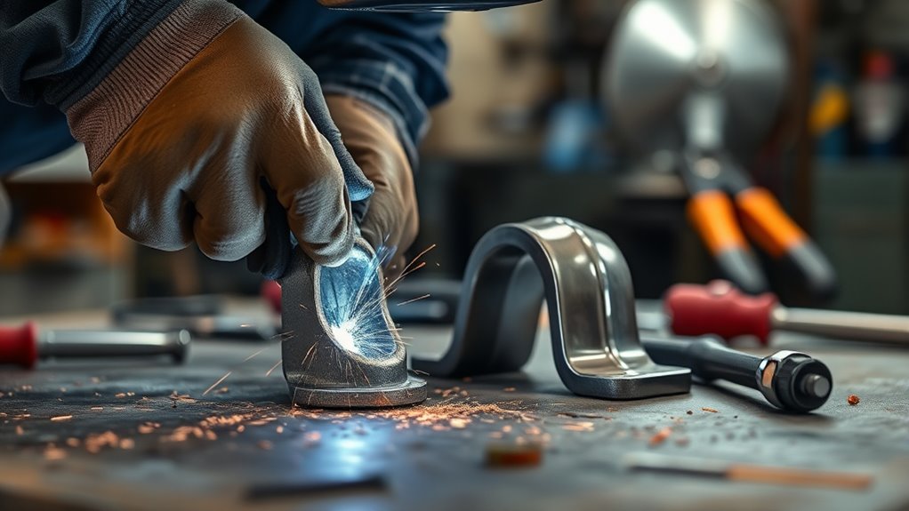
Do not judge the repair while the metal is hot or covered with slag, soot, spatter, developer, or grinding dust. Allow the component to cool as required, then clean it without removing evidence of a defect.
Complete a Visual Inspection
- Check the weld profile: Look for consistent width, smooth transitions, and complete coverage of the designed joint.
- Look for surface defects: Check for cracks, visible porosity, overlap, undercut, arc strikes, missed areas, and incomplete tie-in.
- Inspect the heat-affected area: Look for new cracks, excessive oxidation, melted edges, or heat damage.
- Check all sides: Inspect the root or back side when accessible.
- Inspect nearby features: Check holes, threads, machined faces, bushings, and adjoining welds.
A magnet can offer limited material clues but cannot confirm weld quality or strength. A visually smooth weld can still contain incomplete fusion, an internal crack, or an unsuitable heat-affected zone.
Check Dimensions and Surface Cracks
- Confirm bolt-hole spacing and diameter.
- Check that mounting faces remain flat and parallel where required.
- Verify the bracket angle, offset, and overall dimensions.
- Test-fit the bracket without forcing bolts through misaligned holes.
- Use an appropriate liquid-penetrant process for surface-breaking cracks when the material and repair procedure allow it.
The FAA nondestructive-inspection job aid explains that liquid penetrant inspection requires pre-cleaning, penetrant application, excess removal, developer, and examination. Penetrant results do not establish internal penetration or fatigue life.
For a loaded or safety-sensitive bracket, have a qualified welder, automotive fabricator, engineer, or mechanic review the repair. Additional nondestructive examination may be appropriate for the material and joint.
Use adequate ventilation during welding, grinding, and inspection cleanup. This related guide discusses ventilation and metalworking fume hazards.
Note: Do not grind a weld flush merely to improve its appearance unless the repair drawing requires it. Unnecessary grinding can reduce the effective weld section and hide evidence needed for inspection.
Putting It All Back Together: Reassembly and Aftercare
Reinstall the bracket only after it passes the required visual, dimensional, and additional inspections. Clean the mounting faces and confirm that the repaired component seats without prying, hammering, or forcing bolts into position.
- Position the bracket: Align it with the recorded marks or service-manual reference points.
- Install correct hardware: Replace torque-to-yield, coated, locking, damaged, or otherwise single-use fasteners when specified.
- Start fasteners by hand: Avoid cross-threading or using bolts to pull a misaligned bracket into place.
- Apply the tightening sequence: Follow the manufacturer’s order and preliminary tightening stages.
- Torque to specification: Use the exact values for the vehicle and hardware position.
- Remove support gradually: Watch for bracket movement as the powertrain load returns to the mount.
- Restore nearby components: Route wiring, grounds, hoses, shields, and brackets away from heat, sharp edges, and moving parts.
- Restore electrical systems: Reconnect batteries, modules, or high-voltage systems according to the service procedure.
Wear suitable protective clothing for welding and grinding. Hot spatter and freshly welded metal can cause burns even after the arc has stopped.
Complete a Controlled First Start
Before starting the engine, remove tools and support equipment from moving or hot areas. Confirm that all fluids, grounds, connectors, shields, hoses, and fasteners have been restored.
- Start the vehicle in Park or Neutral with the parking brake applied.
- Keep hands, clothing, tools, and inspection lights away from belts, fans, axles, and exhaust parts.
- Observe the mount from a safe position while the engine starts and idles.
- Listen for contact, clunks, exhaust movement, or abnormal vibration.
- If the vehicle and service procedure permit it, observe controlled load changes with a second qualified person operating the controls.
- Stop immediately if the bracket shifts, the weld area opens, a fastener moves, or another component contacts the body.
After professional acceptance and a normal stationary check, complete only a short, low-load verification drive. Reinspect the mounting faces, fasteners, surrounding paint, nearby components, and weld area after the first heat cycle and again at the interval recommended by the repair professional.
Troubleshooting Common Issues After Welding
Stop driving if vibration, clunking, powertrain movement, fluid leakage, cracked paint, loose hardware, or a new weld indication appears after the repair.
- A crack appears in or beside the weld: The original crack may not have been fully removed, the material or filler may be incompatible, the joint may lack fusion, or heat stress may have created a new crack. Remove the vehicle from service and replace or professionally reassess the component.
- Vibration becomes worse: The bracket may be distorted, the mount may be preloaded, another mount may be damaged, or the exhaust or driveline may be contacting the body.
- Bolts loosen: The hardware, tightening sequence, mounting-face condition, or torque may be incorrect. Do not repeatedly retighten without finding the cause.
- Porosity appears: Contamination, moisture, gas disruption, excessive stick-out, poor surface preparation, or unsuitable parameters may have produced voids. Review common causes of weld porosity and reject the repair until the defect is evaluated.
- The bracket does not fit: Weld shrinkage or an inadequate fixture may have changed the dimensions. Do not use mounting bolts to force it into place.
- Rubber or nearby parts show heat damage: Replace the damaged part and inspect wiring, hoses, seals, coatings, and fluid lines that were exposed.
- Electronic faults appear: Stop diagnosis and scan the vehicle using the correct equipment. Check grounds, connectors, modules, and the vehicle maker’s welding precautions.
- The original failure returns: Check the complete mount set, drivetrain alignment, engine operation, collision damage, crossmember condition, exhaust contact, and fastener integrity.
Frequently Asked Questions
Can an engine mount be welded?
A complete rubber, hydraulic, or electronic engine mount should normally be replaced. Welding may be possible for a removable metal bracket when the material is known, the damage is limited, the vehicle maker permits the repair, and a qualified fabricator can restore the original dimensions and load path.
Should you weld or replace a broken engine mount?
Replace it when the isolator is torn or leaking, the bracket is badly distorted, metal is missing, bolt holes are damaged, the material is unknown, or the crack affects a mounting face or structural attachment. Consider welding only a suitable removable metal bracket under an approved repair procedure.
Can you weld the mount while it is still on the vehicle?
Removing the bracket and welding it on a bench is usually safer. In-vehicle welding should be performed only when the vehicle maker permits it and all required electrical isolation, high-voltage precautions, fire controls, ventilation, work-clamp placement, and hidden-cavity inspections are completed.
How do you identify the mount material?
Use OEM part information, casting or alloy marks, repair documentation, or professional material identification. A magnet, spark pattern, color, or surface texture may provide clues, but none reliably identifies the exact alloy or proves that the component is suitable for welding.
What can JB Weld not fix?
JB Weld and similar epoxies should not replace a metal repair on a loaded engine or transmission mount. They are not a suitable substitute for an intact isolator, an OEM replacement bracket, or a properly designed and inspected structural weld.
What’s the hardest thing to weld on an engine mount?
Unknown castings, contaminated cast iron, thin-to-thick transitions, heat-treated aluminum, high-strength steel, and cracks through machined mounting features are difficult to repair reliably. These conditions usually favor professional evaluation or replacement.
How much would it cost to get a frame welded?
Frame or unibody welding is a different repair from welding a removable mount bracket. Cost depends on structural damage, access, measuring, corrosion, material, approved repair procedures, refinishing, alignment, and inspection. Obtain a written estimate from a qualified collision or structural repair facility.
How do you know if the welded mount is safe?
The repair should match an approved procedure, retain the correct dimensions, pass visual and appropriate nondestructive inspection, fit without force, use correct hardware and torque, and be accepted by a qualified professional. A good-looking bead or a short test drive alone does not prove safety.
Safety Disclaimer: This article provides general information and does not replace the vehicle manufacturer’s service procedure, an engineered weld-repair specification, or professional mechanical and welding advice. Engine and transmission mounts affect vehicle control, component clearance, and drivetrain alignment. Replace or professionally inspect a damaged mount before returning the vehicle to public-road use.
Conclusion
Replacing a broken engine or transmission mount is usually safer than welding it. A welded repair should be limited to a suitable removable metal bracket with known material, limited damage, OEM permission, correct powertrain support, controlled preparation, an approved welding procedure, and appropriate inspection.
Do not weld rubber or hydraulic isolators, unknown castings, badly distorted parts, damaged bolt bosses, or structural body and subframe attachments using a generic method. When the repair is approved, remove the bracket when practical, protect the vehicle’s electrical and fuel systems, avoid hazardous cleaner residue, restore the original alignment, and reinstall it with the specified hardware and torque.
Sources
- OSHA 29 CFR 1910.252: General Welding, Cutting, and Brazing Requirements — fire prevention, combustible control, and hot-work safety.
- CDC Medical Management Guidelines for Phosgene — toxic gas formation when chlorinated hydrocarbons are exposed to welding heat.
- Miller Bobcat 250 Operator’s Manual — battery disconnection and close work-clamp placement when welding on vehicles.
- Lincoln Electric Guidelines for Welding Cast Iron — cast-iron preparation, preheat, welding, and controlled cooling considerations.
- Tesla Model 3 Motor Mount Isolator Replacement Procedure — example of OEM replacement, fastener, and torque requirements.
- FAA Nondestructive Inspection Job Aid — proper liquid-penetrant inspection steps and limitations.




