A clean cut makes accurate weld fit-up much easier. Jagged edges, heavy dross, excessive heat, and wandering cuts can create uneven root openings, increase cleanup, and make distortion harder to control. The right metal cutting method depends on the material, thickness, shape, required accuracy, available power, and where the work will be done.
Oxy-fuel, plasma, cutoff wheels, saws, shears, lasers, and waterjets all have a place in fabrication. This guide explains how each process works, where it performs best, what can go wrong, and how to prepare the finished edge for welding without relying on unsafe one-size-fits-all settings.
Quick Answer
Use oxy-fuel for thick carbon steel, plasma for fast cuts on conductive metals, cutoff wheels or saws for portable shop work, laser for accurate production parts, and waterjet when you need a cold cut without a heat-affected zone. Always follow the machine’s cut chart and the project’s welding procedure.
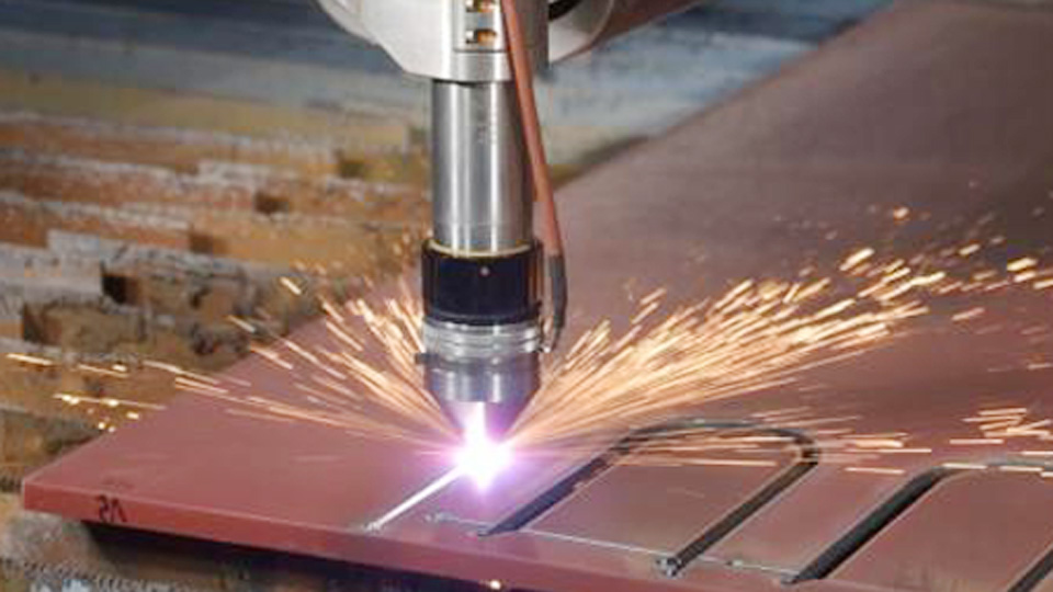
Image by thefabricator
Key Takeaways
- Match the cutting process to the metal, thickness, required shape, tolerance, and work location.
- Never use generic gas pressures, travel speeds, or amperage settings when the manufacturer provides a tip chart or cut chart.
- Oxy-fuel is mainly for carbon and some low-alloy steels, while plasma cuts electrically conductive metals such as steel, stainless steel, aluminum, copper, and brass.
- Inspect cutoff wheels, confirm their marked RPM, keep the guard installed, and never side-load a cutting-only wheel.
- Prepare bevel angle, root face, and root opening from the drawing or welding procedure specification rather than using one universal dimension.
Why Metal Cutting Matters in Welding
A good weld starts with predictable fit-up. A rough or tapered cut can change the joint opening from one end to the other, while heavy oxide or dross can contaminate the weld area. Extra grinding also removes time and may change the intended joint dimensions.
The cutting process affects more than appearance. It controls kerf width, edge squareness, heat input, distortion, burr formation, and cleanup time. A kerf is the slot of material removed by the cut. Dross is resolidified metal left along the lower edge. A heat-affected zone, or HAZ, is the area beside a thermal cut where heat may change the metal’s structure or properties.
Metal Cutting Methods Compared
| Method | Best Use | Compatible Materials | Edge and Heat | Portability |
|---|---|---|---|---|
| Oxy-fuel | Thick plate, field repair, beveling, demolition | Carbon steel and some low-alloy steels | Wide HAZ; slag and oxide cleanup often required | High |
| Plasma | Fast straight or shaped cuts on sheet and plate | Any electrically conductive metal | Narrower HAZ than oxy-fuel; possible dross and bevel | Medium; requires power and gas or air |
| Abrasive wheel | Small jobs, trimming, tube, angle, and sheet | Most metals with the correct wheel | Heat, sparks, burrs, and wheel dust | High |
| Laser | Accurate CNC parts and production nesting | Machine-dependent; commonly steel, stainless, aluminum, brass, and copper | Narrow kerf and limited cleanup when tuned correctly | Low |
| Saw or shear | Square cuts, straight sheet cuts, bar, tube, and profiles | Many metals with the correct blade or shear capacity | Little thermal effect; may leave burrs or edge rollover | Medium |
| Waterjet | Heat-sensitive alloys, accurate profiles, and mixed materials | Nearly any material within machine capacity | No thermal HAZ; possible taper and abrasive residue | Low |
Oxy-Fuel Cutting
Oxy-fuel cutting, also called flame or torch cutting, uses a fuel-gas flame to preheat steel and a concentrated oxygen stream to oxidize and remove the metal. The oxygen reaction does most of the cutting. The preheat flame keeps the steel at the temperature needed for the reaction to continue.
Products Worth Considering

High quality medium duty cutting torch CA1350 cutting attachment, 100FC torch handle.

Powerful Flame Temperature Heat up to 5252°F (2900°C)

High quality heavy duty cutting torch CA2460 cutting attachment, 315FC torch handle.
How Oxy-Fuel Cutting Works
First, the torch heats the starting point until the steel reaches its kindling temperature. Pressing the cutting-oxygen lever starts rapid oxidation. The oxygen jet blows the resulting iron oxide from the kerf while the operator moves the torch at a controlled speed.
A quality cut has a reasonably square face, nearly vertical drag lines, a controlled top-edge radius, and slag that is light enough to remove without heavy grinding. Tip condition, tip height, oxygen purity, pressure, preheat adjustment, travel speed, and plate condition all affect the result.
When to Use Oxy-Fuel
Oxy-fuel performs best on carbon steel and certain low-alloy steels. It is especially useful for thick plate, field repairs, demolition, and weld bevels where portability matters. Standard oxy-fuel cutting does not work well on aluminum or stainless steel because their oxides do not support the same cutting reaction.
There is no single minimum or maximum thickness that applies to every torch. Choose the tip, gas, pressures, and travel speed from the torch manufacturer’s chart for the exact fuel gas and plate thickness.
Practical Tips for Oxy-Fuel
- Inspect before lighting: Check the torch, tip, hoses, regulators, check valves, and flashback protection. Remove damaged equipment from service.
- Use the approved lighting sequence: Follow the torch manufacturer’s instructions instead of relying on a fixed oxygen-to-fuel ratio.
- Use the correct tip chart: Tip size and regulator pressure depend on the torch, fuel gas, and steel thickness.
- Keep the tip clean: A damaged or clogged orifice can disturb the oxygen stream and produce a rough, tapered cut.
- Control travel speed: Heavy slag and deeply curved drag lines can indicate incorrect speed, height, oxygen flow, or tip condition.
- Support the drop: Arrange the work so the falling section cannot pinch the kerf, strike a hose, or land on your feet.
Warning: Never use acetylene above 15 psig. Do not guess regulator pressures, use oil on oxygen equipment, or light a torch before checking for leaks. Follow the torch-tip chart and the applicable OSHA oxygen-fuel requirements.
Pros and Cons of Oxy-Fuel
| Pros | Cons |
|---|---|
| Effective on thick carbon-steel plate | Normally unsuitable for stainless steel and aluminum |
| Portable and independent of electrical power | Produces a wider HAZ than most plasma cuts |
| Useful for beveling, demolition, and field repair | Requires fuel-gas handling and fire controls |
| Equipment can be economical for occasional work | Often leaves oxide and slag that must be removed |
Plasma Cutting
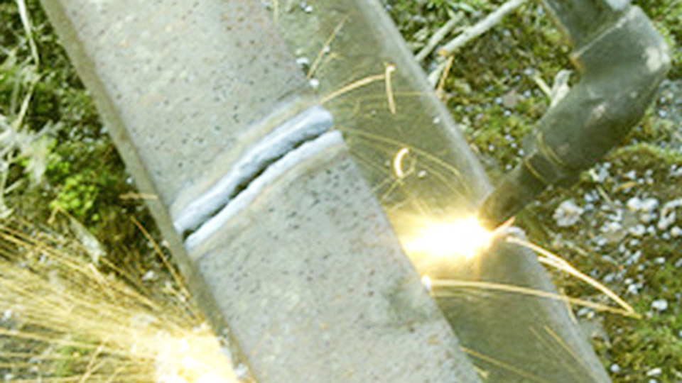
Plasma cutting forms an electrical arc through a high-velocity stream of ionized gas. The arc melts the metal, and the gas jet removes it from the kerf. Because the electrical circuit passes through the workpiece, plasma cutting is limited to electrically conductive materials.
How Plasma Cutting Works
The power supply creates an arc between the torch electrode and the workpiece. Compressed air or another approved gas passes through the torch and becomes plasma. The constricted plasma jet concentrates heat into a small area while the gas ejects molten metal from the cut.
Manual systems commonly use compressed air, but the air must meet the machine’s pressure, flow, cleanliness, and dryness requirements. Water, compressor oil, or dirt in the air supply can shorten consumable life and destabilize the cut.
When to Use Plasma
Plasma is a strong choice for mild steel, stainless steel, aluminum, copper, brass, and other conductive metals. It works well for automotive sheet metal, brackets, signs, HVAC work, structural parts, repair work, and CNC profiles.
Capacity is machine-specific. Manufacturers distinguish between a recommended cut capacity, which targets useful speed and quality, and a slower severance capacity, which is intended mainly to separate the material. The manufacturer’s system and cut charts should control machine selection and settings.
Practical Tips for Plasma
- Start with the cut chart: Match amperage, consumable, gas pressure, torch height, pierce height, delay, and travel speed to the machine and material.
- Use clean, dry air: Drain the compressor and maintain the approved filters and dryer.
- Make a sound work connection: Attach the work lead to clean metal on the section that will remain supported.
- Use the correct consumables: Do not mix parts from different amperage ranges or cutting processes.
- Keep the torch square: An angled torch creates a wider bevel on one side of the kerf.
- Use a guide when needed: A straightedge, circle guide, or template can improve consistency on manual cuts.
Pro Tip: Read the dross before reaching for the grinder. Dross that forms because travel speed is too low behaves differently from dross caused by excessive speed, worn consumables, incorrect height, or poor air quality. Change one variable at a time and compare the result with the cut chart.
Pros and Cons of Plasma
| Pros | Cons |
|---|---|
| Cuts most electrically conductive metals | Requires electrical power and an approved gas supply |
| Fast on sheet and medium plate | Consumables and air quality affect operating cost |
| Can make straight lines and complex profiles | May leave dross, bevel, and a heat-affected edge |
| Manual systems can be easy to learn | Cut capacity depends on the exact machine |
Abrasive Cutting With Grinding and Cutting Wheels
Abrasive cutting uses a high-speed wheel to remove metal from the kerf. A handheld angle grinder is affordable and portable, while an abrasive chop saw provides a fixed base for repeatable crosscuts.
How Abrasive Cutting Works
A cutoff wheel contains bonded abrasive grains that wear away as they cut. A thin wheel creates a narrower kerf than a grinding wheel, but it is also more vulnerable to twisting, side pressure, impact, and incorrect mounting.
For tubing, angle, bar, and small sheet-metal jobs, abrasive cutting can be practical when plasma or a band saw is unavailable. The correct wheel must be rated for the material, machine type, wheel diameter, and spindle speed.
When to Use Abrasive Cutting
Use an angle grinder for trimming, short straight cuts, notches, damaged fasteners, tubing, angle iron, and occasional sheet-metal work. It can cut thicker stock, but progress becomes slower and wheel use increases as the section grows.
Choose a wheel specifically approved for the metal. Aluminum and other nonferrous metals may require wheels designed to resist loading. Never assume that one wheel is suitable for every alloy.
Practical Tips for Abrasive Cutting
- Read the wheel label: Confirm the wheel type, material application, diameter, arbor, and maximum RPM.
- Inspect the wheel: Do not use a cracked, chipped, wet, expired, dropped, or otherwise damaged wheel.
- Keep the guard installed: Position it between your body and the wheel so fragments and sparks are directed away from you.
- Use two hands: Hold the main grip and side handle, establish stable footing, and allow the wheel to reach full speed before entering the cut.
- Avoid twisting: Keep the wheel aligned with the kerf. Do not pry sideways or use the side of a cutting-only wheel for grinding.
- Support both sides correctly: Prevent the closing kerf from pinching the wheel, but make sure the cutoff cannot fall or swing into the tool.
- Let the wheel cut: Excessive force increases heat, deflection, binding, and breakage risk.
Warning: A face shield does not replace impact-rated safety glasses. Use both, keep the grinder guard installed, and verify that the wheel’s marked maximum speed is at least as high as the grinder speed. OSHA also requires the guard to be positioned between the operator and wheel on a right-angle grinder. See OSHA’s portable-tool guarding requirements.
Pros and Cons of Abrasive Cutting
| Pros | Cons |
|---|---|
| Affordable and widely available | Creates sparks, dust, noise, and sharp burrs |
| Portable and useful for repairs | Slow and costly in wheel use on thick sections |
| Works on many metals with the proper wheel | Cut accuracy depends heavily on operator control |
| Useful for trimming and access-limited work | Binding or side-loading can break the wheel |
Laser Cutting
Laser cutting concentrates a high-energy beam into a small spot and uses an assist gas to remove molten or vaporized material. CNC motion allows the machine to produce detailed profiles, small features, and nested production parts with a narrow kerf.
How Laser Cutting Works
The laser source, focusing optics, nozzle, assist gas, cutting head, motion system, and control software work together. Oxygen, nitrogen, compressed air, or another approved gas may be used depending on the machine, material, edge requirement, and process.
Modern industrial laser capacity varies widely. Power level alone does not determine the result. Material grade, thickness, surface condition, beam delivery, focal position, nozzle, gas purity, pressure, piercing strategy, and manufacturer parameter library all matter.
When to Use Laser
Laser cutting is well suited to accurate sheet and plate parts, intricate contours, small holes, repeat production, automated nesting, and jobs where a narrow kerf reduces material waste. It is common in automotive, aerospace, appliance, enclosure, architectural, and contract-fabrication work.
Small welding shops often outsource laser-cut parts rather than buy and maintain a machine. Outsourcing can make sense when the parts need tight repeatability, many identical profiles, or details that would take too long to produce manually.
Practical Tips for Laser
- Use the approved parameter library: Do not transfer power, speed, gas, or focus settings from a different machine.
- Confirm material identity: Grade, thickness, coating, and protective film can change the required process.
- Maintain optics and nozzles: Contamination, damage, or poor nozzle centering can reduce cut quality.
- Keep extraction operating: Laser cutting generates fumes, fine particles, and process gases that require suitable collection.
- Respect enclosures and interlocks: Never bypass a door, panel, or safety circuit to keep production running.
- Inspect the edge: Check burr, dross, oxide, taper, and surface condition before sending parts to welding.
Note: Industrial laser cutters contain hazards that are not comparable to a handheld cutting tool. Operation, servicing, extraction, enclosure controls, and protective equipment must follow the machine manufacturer’s procedures and the facility’s laser-safety program.
Pros and Cons of Laser
| Pros | Cons |
|---|---|
| Narrow kerf and high repeatability | High purchase, installation, and maintenance cost |
| Fast production of nested parts | Requires trained operators and controlled parameters |
| Can produce detailed shapes and small features | Fumes, optics, assist gas, and extraction require management |
| Often needs little edge cleanup when tuned correctly | Not practical as a portable field-cutting process |
Mechanical Cutting With Shears and Saws
Mechanical cutting separates metal with blades rather than an arc or flame. Common options include hand and powered shears, hydraulic guillotines, band saws, cold saws, reciprocating saws, and toothed chop saws.
How Mechanical Cutting Works
A shear forces two blades past each other to separate sheet metal. It is fast for straight lines but can leave burrs, edge rollover, or slight distortion if blade clearance is wrong or the material exceeds the machine capacity.
A band saw uses a continuous toothed blade and is useful for tube, bar, angle, pipe, and structural profiles. A cold saw uses a toothed circular blade at controlled speed. These processes produce chips rather than the shower of sparks associated with an abrasive chop saw.
When to Use Mechanical Cutting
Use a shear for straight sheet-metal cuts within the rated thickness and material capacity. Use a band saw or cold saw when you need a square crosscut, a controlled miter, low thermal input, or repeatable cuts on tube and profiles.
Mechanical cutting is valuable when you want to avoid a thermal HAZ. It may still create localized friction heat, burrs, blade marks, or deformation, so inspect the edge before welding.
Practical Tips for Mechanical Cutting
- Select the correct blade: Match tooth pitch, blade material, speed, and feed to the alloy and section size.
- Clamp the work: Movement can strip teeth, pull the material, create a crooked cut, or jam the blade.
- Support long stock: Use stands or conveyors so the material cannot tip, bind, or fall after separation.
- Use approved cutting fluid: Follow the machine and blade manufacturer’s guidance for the material.
- Keep guards and covers closed: Do not reach through a moving blade path or clear chips by hand.
- Avoid loose clothing and gloves near exposed rotation: Follow the machine-specific PPE rules and use tools for chip removal.
- Replace dull blades: Excessive feed pressure will not correct a worn, damaged, or unsuitable blade.
Pros and Cons of Mechanical Cutting
| Pros | Cons |
|---|---|
| Little or no metallurgical heat-affected zone | Usually slower than plasma or laser on profiles |
| Band and cold saws can produce square cuts | Blades require correct selection and maintenance |
| Shears are fast for straight sheet cuts | Shears are limited to straight cuts and rated capacity |
| Produces less fume than thermal cutting | Can leave burrs, tooth marks, rollover, or distortion |
Waterjet Cutting
Abrasive waterjet cutting uses a high-pressure stream of water mixed with abrasive particles to erode the material. Because it is a cold-cutting process, it does not create the thermal HAZ associated with oxy-fuel, plasma, or laser cutting.
When to Use Waterjet
Waterjet is useful for stainless steel, aluminum, carbon steel, titanium, hardened alloys, reflective metals, composites, stone, and other materials that may be difficult or risky to cut thermally. It is especially valuable when heat could affect hardness, flatness, coating condition, or material properties.
Shops often use waterjet for accurate profiles, prototypes, thick mixed materials, and parts that need minimal thermal preparation before welding. Capacity and accuracy still depend on the machine, pump, nozzle, abrasive, material, thickness, and programmed quality level.
Practical Tips for Waterjet Parts
- Specify the required edge quality rather than assuming every waterjet cut has the same finish.
- Account for possible kerf taper on thick material or faster quality settings.
- Remove abrasive residue, moisture, and trapped slurry before fit-up and welding.
- Check small tabs, corners, and pierce points for erosion or localized damage.
- Confirm that the part is fully dry before it enters a joint, fixture, or enclosed cavity.
Pros and Cons of Waterjet
| Pros | Cons |
|---|---|
| No thermal heat-affected zone | Equipment and operating costs can be high |
| Cuts a wide range of metals and nonmetals | May cut more slowly than thermal processes |
| Useful for heat-sensitive and reflective materials | Can leave taper, moisture, and abrasive residue |
| Produces accurate profiles with little thermal distortion | Not portable and requires slurry management |
Choosing the Right Metal Cutting Method
Choose the process by working through the job requirements in order. Start with material compatibility, then compare thickness, geometry, tolerance, edge condition, production quantity, available equipment, portability, and safety controls.
Products Worth Considering

Complete Kit: Medium-Duty Cutting & Welding - This versatile Oxy Acetylene Torch Kit is built for medium-duty projects. Achieve clean cuts up to 6 inches and precise welding/brazing on materials up to 1/2 inch thick with the appropriate tips
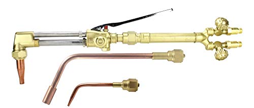
Select the Configuration You Need This listing offers multiple Victor-style Series 300 replacement options: Torch Handle only, Cutting Attachment only, Acetylene Cutting, Acetylene Cutting + Welding/Brazing, Acetylene Cutting + Welding/Brazing + Heating, LPG/Propane Cutting, and LPG/Propane Cutting + Heating. Please choose the correct variation before purchasing.

High-Quality:The Oxygen Acetylene Torch Welding and Cutting Kit is made of high quality stainless steel and brass for durability. This oxygen & acetylene torch kit comes complete with hoses, welding and cutting torches, goggles, tip cleaner and spark igniter, and more A 17-piece professional-grade portable oxygen acetylene oxy welding cutting torch kit that includes everything you need to weld or cut accurately,allowing you to cut, weld, braze, and fuse accurately and efficiently!
Quick Decision Guide
- Thick carbon-steel plate in the field: Start by considering oxy-fuel.
- Fast cuts on conductive sheet or plate: Consider plasma within the machine’s recommended capacity.
- Small repair or occasional shop cut: Use a rated cutoff wheel, reciprocating saw, or suitable band saw.
- Square tube, bar, pipe, or repeat crosscuts: Use a band saw or cold saw.
- Straight sheet-metal blanks: Use a shear within its rated material capacity.
- Detailed production parts: Consider laser cutting or outsource the work.
- Heat-sensitive material or no-HAZ requirement: Consider waterjet or an appropriate mechanical process.
Scenario 1: Heavy Steel Fabrication
You are fabricating a frame from heavy carbon-steel plate. Oxy-fuel may be economical and portable, especially when the plate is beyond the efficient range of the available plasma system. High-amperage plasma may be faster when the shop already has suitable power, gas, extraction, and material-handling equipment.
Whichever process you use, inspect the cut face, remove unacceptable notches and oxide, and prepare the groove according to the drawing and welding procedure.
Scenario 2: Automotive Sheet-Metal Repair
You are making a patch for non-structural automotive sheet metal. Plasma, snips, a nibbler, a cutoff wheel, a reciprocating saw, or a shear may work depending on access and shape. Control heat, protect wiring and fuel systems, and test the process on matching scrap before cutting the vehicle.
Warning: Do not treat a frame rail, unibody load path, suspension mount, seat-belt anchor, battery enclosure, or other structural vehicle component as a routine DIY patch. Follow the vehicle manufacturer’s repair procedure and use a qualified repair professional when structural integrity is involved.
Scenario 3: DIY Home Project
You are building a steel workbench from angle and square tube. A horizontal band saw gives repeatable square cuts, while an angle grinder is useful for trimming and notching. Mark every piece from the same reference, clamp it securely, and leave enough material for final fitting.
Factors to Consider
Material: Oxy-fuel is mainly for carbon and some low-alloy steels. Plasma requires electrical conductivity. Abrasive wheels and saws need the correct wheel or blade. Laser and waterjet compatibility depends on the machine and process.
Thickness: Do not use one thickness rule for every machine. Compare the exact torch tip, plasma cut chart, shear rating, saw capacity, laser parameter library, or waterjet specification.
Geometry: Shears are for straight cuts. Saws are strong at crosscuts and miters. Plasma, laser, and waterjet handle contours. A grinder is useful for access-limited trimming but is harder to guide accurately over long distances.
Precision: Laser and waterjet generally suit detailed profiles. A well-set saw can produce square crosscuts. Manual oxy-fuel, plasma, and abrasive cuts usually need more allowance for operator variation.
Heat: Oxy-fuel, plasma, laser, and abrasive cutting introduce heat. Waterjet and most mechanical processes avoid a metallurgical HAZ, although friction and deformation can still affect the edge.
Budget and production: A grinder or saw may be practical for occasional work. Plasma can improve speed in small and medium shops. Laser and waterjet become more attractive for complex parts, repeat production, or outsourced near-net shapes.
Portability: Handheld grinders, portable saws, and oxy-fuel equipment can work in the field. Plasma requires suitable electrical power and gas or compressed air. Industrial laser, shear, and waterjet systems are shop machines.
Code and procedure requirements: A cutting process does not automatically make the finished edge code-compliant. The drawing, contract, welding procedure specification, and applicable edition of a code such as AWS D1.1/D1.1M determine preparation and acceptance requirements.
Common Cut-Quality Problems and Fixes
| Symptom | Possible Causes | What to Check |
|---|---|---|
| Heavy oxy-fuel slag | Incorrect speed, tip size, oxygen setting, tip height, or dirty tip | Tip chart, orifice condition, preheat adjustment, oxygen stream, and travel speed |
| Plasma dross | Speed or height error, worn consumables, poor air, wrong amperage | Cut chart, consumable set, air pressure and dryness, torch height, and work connection |
| Plasma bevel on one side | Torch not square, worn nozzle, incorrect cut direction, excessive speed | Torch angle, consumables, travel direction, and speed |
| Cutoff wheel binds or wanders | Closing kerf, side pressure, poor support, excessive force, damaged wheel | Work support, wheel alignment, wheel condition, body position, and cutting pressure |
| Band-saw cut is crooked | Dull blade, wrong tooth pitch, loose blade, excessive feed, poor clamping | Blade selection, tension, guides, feed rate, vise, and machine alignment |
| Laser burr or incomplete cut | Incorrect parameter set, focus, nozzle, gas, optics, or material data | Approved parameter library, nozzle centering, lens condition, gas supply, and material identity |
| Waterjet taper or rough edge | Fast quality setting, worn nozzle, incorrect abrasive flow, thick material | Programmed quality, nozzle condition, standoff, abrasive delivery, and machine calibration |
Weld Prep After Cutting
No cutting process guarantees a weld-ready edge. Inspect and prepare the joint before tacking so you do not trap oxide, abrasive, moisture, coatings, or dimensional errors in the weld.
- Confirm the part dimensions: Check length, angle, squareness, hole position, and joint alignment against the drawing.
- Inspect the cut face: Look for cracks, gouges, sharp notches, deep drag lines, excessive taper, hard burrs, and incomplete cuts.
- Remove loose material: Grind, file, scrape, or machine away dross, slag, burrs, and damaged edge sections.
- Remove coatings and contamination: Clean paint, rust, oil, adhesive, galvanizing, unknown coatings, and moisture from the weld zone using an approved method and exposure controls.
- Prepare the groove: Produce the bevel angle, root face, and root opening specified by the drawing or WPS. Do not substitute a generic 30–45-degree bevel or 1/16-inch gap.
- Check thermal-cut oxide: Some processes and alloys leave an oxide layer or hardened edge that may need grinding or machining before welding.
- Dry-fit and tack: Clamp the parts without forcing them into position. Recheck alignment after the first tacks because the joint can pull as heat builds.
- Select welding consumables from the procedure: Filler classification depends on the base metal, process, shielding gas, service condition, design, and applicable WPS.
Pro Tip: Leave a small amount of finishing allowance when accuracy matters. It is easier to remove a controlled amount with a file, grinder, or machine tool than to rebuild an oversized kerf or a joint that was cut too short.
Safety First: Cutting Done Right
Metal cutting can expose you to fire, hot metal, ultraviolet and infrared radiation, electrical energy, high-pressure gas, wheel fragments, sharp edges, fumes, noise, moving blades, and falling workpieces. PPE is only one part of the control plan.
Warning: Do not thermally cut a sealed container, fuel tank, drum, pipe, pressure vessel, battery enclosure, or unknown vessel. Residue, trapped pressure, or hidden flammable vapor can cause an explosion even when the container appears empty.
Before Cutting
- Read the machine manual, consumable chart, workplace procedure, and safety data for the material or coating.
- Identify paint, galvanizing, lead, cadmium, chromium-bearing material, oil, plastic, foam, insulation, and other contaminants.
- Remove or shield combustible material and arrange a fire watch when the work conditions require one.
- Provide ventilation or local exhaust suitable for the process and material. Do not treat a disposable dust mask as a universal solution for metal fumes.
- Inspect cables, hoses, regulators, wheels, blades, guards, clamps, compressed-air equipment, extraction, and emergency controls.
- Support the workpiece and cutoff so neither section can fall, roll, swing, or pinch the cutting tool.
Eye, Face, Hearing, and Body Protection
Use impact-rated safety glasses with side protection for flying particles. Add a face shield for abrasive cutting and grinding. Select filtered eye and face protection for oxy-fuel and plasma work according to the operation, current, and plate thickness. OSHA’s welding and cutting shade table lists minimum protection levels.
Wear flame-resistant clothing, suitable gloves, hearing protection, and protective footwear. Keep cuffs, synthetic fabric, loose clothing, jewelry, and long hair away from sparks and moving equipment. Follow machine-specific rules where gloves could create an entanglement risk.
During and After the Cut
- Keep your body out of the wheel plane, torch path, falling-part zone, and line of fire.
- Do not leave a running machine unattended or defeat guards and interlocks.
- Allow cut parts and slag to cool in a controlled area. Hot metal may look identical to cold metal.
- Mark or isolate hot parts so another person does not pick them up.
- Inspect the work area for smoldering debris after cutting ends.
- Store cylinders, torches, wheels, blades, and power tools according to their manufacturer’s instructions.
Conclusion
The best metal cutting method is the one that produces the required shape and edge without exceeding the limits of the equipment, material, operator, or welding procedure. Oxy-fuel remains useful for thick carbon steel. Plasma combines speed with broad conductive-metal capability. Abrasive wheels and saws handle portable shop work, while shears make fast straight sheet cuts. Laser and waterjet provide accurate profiles when production needs justify them.
Do not let a convenient rule of thumb replace a cut chart, tip chart, machine rating, drawing, or WPS. Clamp and support the work, control fumes and fire, inspect every cut, and prepare the final edge to the actual joint requirements before you strike an arc.
Frequently Asked Questions
What is the best metal cutting method for beginners?
A band saw, reciprocating saw, shear, or guarded angle grinder can be practical for simple beginner projects. The safest choice depends on the material and shape. Start on securely clamped scrap, use the correct blade or wheel, keep every guard installed, and learn the tool’s kickback and pinch hazards before cutting project parts.
Can I use oxy-fuel cutting for aluminum or stainless steel?
Standard oxy-fuel cutting is mainly used for carbon steel and certain low-alloy steels. Aluminum and stainless steel form oxides that prevent the normal rapid-oxidation cutting reaction. Plasma, abrasive cutting, sawing, laser, or waterjet is usually more suitable.
How do I reduce dross when plasma cutting?
Use the exact machine cut chart, then check travel speed, amperage, torch height, consumable condition, cut direction, air pressure, and air dryness. Make sure the work lead has clean contact. Change one variable at a time because both excessive and insufficient speed can leave dross.
Is laser cutting worth it for a small welding shop?
Buying a laser may be difficult to justify unless the shop has enough repeat work to support the machine, extraction, gas, maintenance, software, training, material handling, and floor space. Many small shops get the accuracy benefits by outsourcing laser-cut blanks and welding the finished parts in-house.
How do I prepare cut edges for welding?
Check the dimensions and cut face, then remove slag, dross, burrs, oxide, coatings, oil, moisture, and damaged metal. Prepare the bevel, root face, and root opening shown on the drawing or WPS. Dry-fit the joint and confirm alignment before tacking.
Which cutting method creates no heat-affected zone?
Abrasive waterjet does not create a thermal heat-affected zone. Shearing, band sawing, and cold sawing also avoid the thermal HAZ associated with a flame, plasma arc, or laser, although mechanical processes can still leave burrs, deformation, blade marks, or localized friction heat.
Can I use an angle grinder without its guard when the guard blocks the cut?
No. Select a suitable tool, wheel, guard, and approach that allow the work to be completed with the guard installed. The guard helps deflect sparks and fragments and provides critical protection if the wheel breaks. Never modify the guard or use an oversized wheel.
Does a clean-looking plasma or laser edge automatically meet a welding code?
No. Visual cleanliness alone does not establish compliance. The applicable drawing, contract, WPS, code edition, and inspection requirements determine whether the edge preparation, roughness, discontinuities, dimensions, and joint geometry are acceptable.
Sources
- OSHA 29 CFR 1910.253: Oxygen-Fuel Gas Welding and Cutting — acetylene-pressure limits, approved equipment, hoses, regulators, and fuel-gas safeguards.
- OSHA Eye Protection During Welding and Cutting Fact Sheet — minimum filter-shade guidance for oxygen and plasma cutting.
- OSHA 29 CFR 1910.243: Guarding of Portable Powered Tools — portable-grinder guards, wheel inspection, and maximum-speed compatibility.
- Hypertherm Powermax System Comparison — machine-specific amperage ranges and recommended versus severance capacities.
- OMAX Waterjet Cutting Compared With Other Methods — cold-cutting characteristics, material range, and absence of a thermal HAZ.
- AWS D1.1/D1.1M:2025-AMD1 Structural Welding Code—Steel — current structural-steel welding, fabrication, qualification, inspection, and acceptance framework.