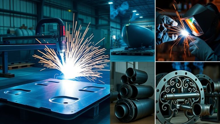
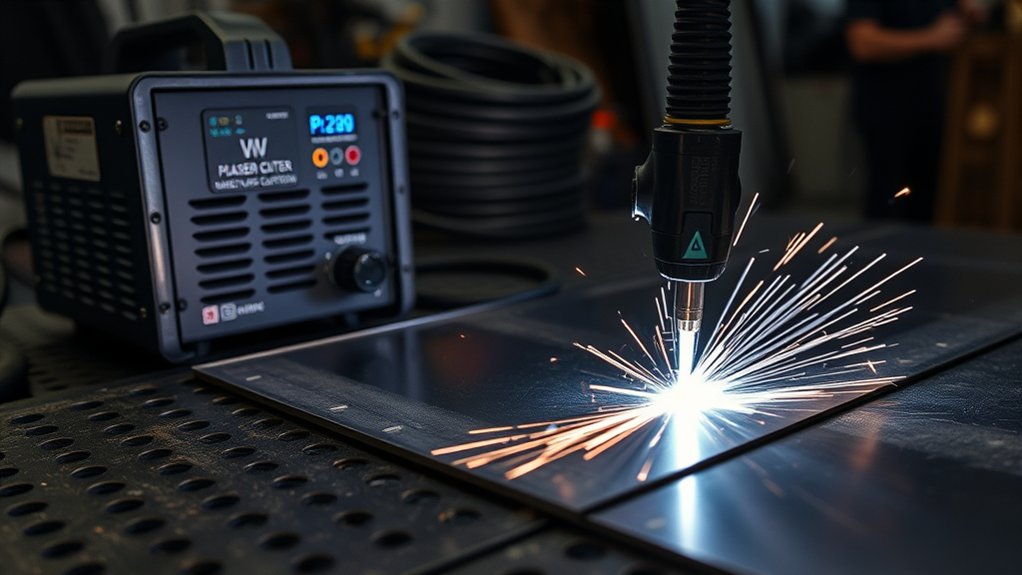
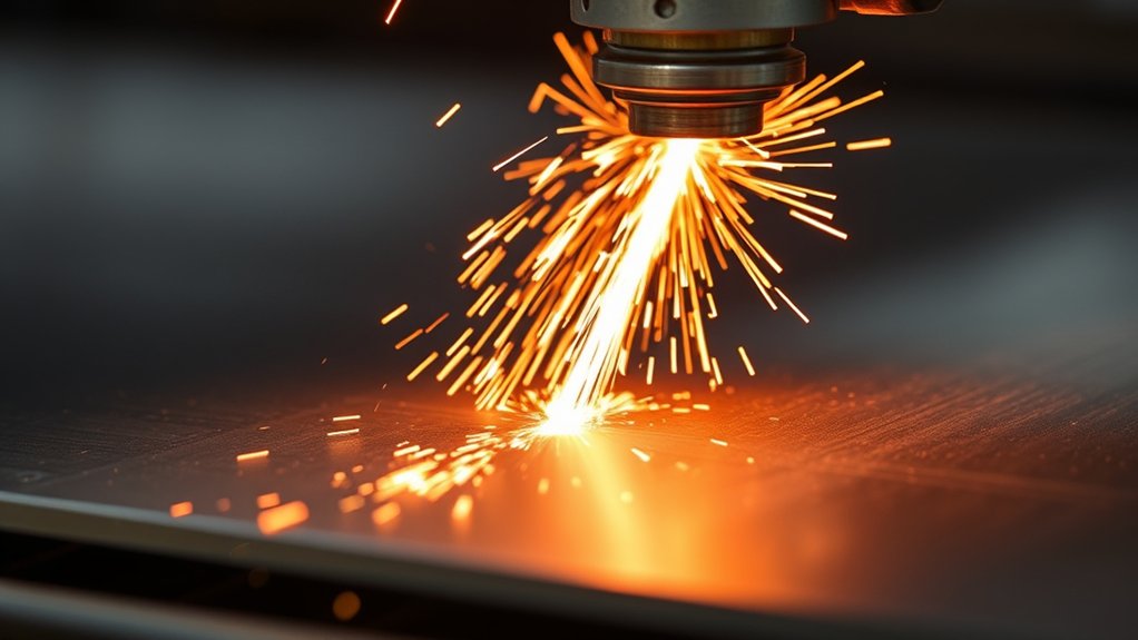
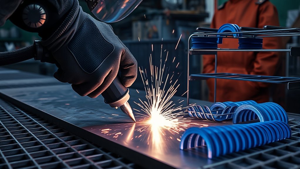
A blue-white arc snaps across sheet metal as you chase a tight contour, and the panel oil-cans from heat load. You want crisp kerfs in 0.5–1.5 mm steel without potato-chipping. To get there, tune your amperage down, push traverse speed near 350 IPM, lock in FineCut consumables, and hold torch height tight with THC. Pair that with proper air quality, solid fixturing, and water-table cooling. Get these fundamentals right, and the next moves (lead-ins, pierce timing, and pathing) decide the outcome.
Quick Answer
- Use FineCut consumables and a 30–40 A inverter to get a narrow, stable kerf on thin steel.
- Push travel speed high (around 350 IPM on 22 ga) and keep amperage low to minimize heat input.
- Lock standoff with Automatic Torch Height Control (THC) to prevent arc stretch and extra heat.
- Clamp or fixture sheets flat before cutting, and use a water table to quench heat and suppress warping.
- Cut inside features first, work outward, and keep lead-ins off the finished edge.
Why Thin Steel Warps and How Plasma Heat Affects It
Thin steel has low mass and stiffness, so it heats up and moves fast under a plasma arc. Warping happens when localized melt pools form and cool unevenly. The concentrated energy source expands the heat-affected zone (HAZ). As the HAZ contracts, residual stresses cause bowing and distortion.
Thin sheet heats fast; uneven cooling and HAZ contraction drive warping, bowing, and distortion under a plasma arc.
If the sheet isn’t fixtured or your traverse speed is too slow, the puddle grows, edges collapse, and panels potato-chip.
Use process control to limit input energy. Prioritize high travel speed, correct amperage, and tight kerf to shrink the thermal footprint. Stabilize standoff with Automatic Torch Height Control (THC) to maintain consistent arc voltage and avoid arc stretch, which spikes heat.
Fixture the sheet with clamps or magnets to resist movement. A water table or water film below the kerf extracts heat and suppresses distortion. Sequence cuts from inside features outward, skip around to distribute heat, and allow brief pauses for thermal equalization.
Choosing the Right Plasma Cutter for 0.5–1.5 mm Steel
Size the machine by duty cycle to match your workload. Occasional cuts suit a 30–35% unit like a Powermax 30 XP, while continuous production calls for 100% duty cycle machines such as a Powermax 65.
For precision and kerf control on 0.5–1.5 mm sheet, spec FineCut consumables and maintain high traverse speeds (around 350 IPM on 22 ga) to limit heat input.
Match power and consumables to torch height control and a water table to stabilize the sheet, tighten kerf, and suppress warping.
Products Worth Considering

50A Power for Everyday Metal Cutting:This 110V/220V dual voltage plasma cutter is designed for cutting steel, stainless steel, aluminum and copper. With proper air pressure and settings, it can make clean cuts up to 1/2" steel for common DIY and repair projects.

![ARCCAPTAIN Plasma Cutter, [Large LED Display] 50Amps Cutter Machine with 110/220V Dual Voltage DC Inverter IGBT 1/2 Inch Clean Cut Post Flow and 2T/4T, for Beginners DIY](https://m.media-amazon.com/images/I/418eA5bRMGL._SL500_.jpg)
【Powerful Cutting Ability】Switch effortlessly between 110V and 220V for home or workshop use. Achieve professional 1/2" clean cuts on steel, aluminum, and copper with advanced LGBT technology. Perfect for DIY projects and heavy-duty tasks. Recommended maximum cutting thickness: 12mm @ 35A / 110V / 55 PSl; 18mm @ 50A / 220V / 75 PSI. Note: Requires compressed air (compressor sold separately).
Duty Cycle Needs
Although thin sheet cuts quickly, duty cycle still governs throughput and uptime when you’re processing 0.5–1.5 mm steel. Check duty cycle impact against your takt time and nest size before selecting a model.
A handheld unit like the Hypertherm Powermax 30 XP at 35% duty cycle suits intermittent cutting, short nests, and job-shop work. For longer runs and higher utilization, an industrial platform such as the Hypertherm Powermax 85 SYNC at 60% duty cycle sustains more arc-on time per hour.
Match amperage to thickness to avoid unnecessary heat input. On 0.5 mm stainless, run lower amps and faster travel (around 350 IPM on 22 ga) to limit thermal load and reduce pause frequency.
Use FineCut consumables to maintain arc stiffness at high speed. Add water tables to buffer heat during extended cycles.
Precision and Kerf
For thin-gauge steel, prioritize a plasma platform that delivers tight kerf control and repeatable cut geometry.
You need a system optimized for precision cutting, with predictable kerf width across 0.5–1.5 mm stock. Specify a torch that supports FineCut consumables. They generate a narrower kerf and reduce edge bevel, improving feature fidelity on intricate profiles.
Integrate closed-loop torch height control (THC) to lock in standoff, stabilize arc voltage, and hold cut width tolerance over minor surface variance.
Run fast traverse and cut speeds (around 350 IPM on 0.5 mm) to limit heat input, suppress warping, and sharpen corner definition. Pair this with a water table to pull heat from the kerf line and clean the edge.
Calibrate amperage to thickness. Lower current tightens the arc column and improves edge quality.
Power and Consumables
Tight kerf control starts with the right powerplant and consumables package. For 0.5–1.5 mm steel, spec a 30–40 A inverter that supports fine cut consumables. They tighten the arc column, yield narrow kerfs, and deliver cleaner edges.
Target a unit with stable low-current performance and a consistent arc start to take advantage of modern plasma technologies.
Running at 30 A with a 35% duty cycle is typical for light fabrication. The Hypertherm Powermax series fits well, offering reliable output for thin-gauge work.
Program fast traverse at about 350 IPM to limit heat input and reduce warping. Pair with a water table or submerged cutting to sink heat and suppress distortion.
Maintain tip standoff precisely, monitor swirl ring condition, and replace nozzles and electrodes on schedule to preserve cut quality.
Essential Setup: Air, Power, and Torch Height Control
Every reliable thin-steel plasma setup starts with clean, dry air, adequate power, and precise torch height control.
Start with air management. Spec an oil-free compressor with a refrigerated dryer or desiccant stage. Add multi-stage air filtration at the plasma inlet, and schedule compressor maintenance to purge condensate and verify regulator setpoints. Dry air suppresses dross and protects valves and solenoids.
Power next: match machine output and duty cycle to your cut plan. A compact unit like the Hypertherm Powermax 30 XP handles thin sheet efficiently, but watch its 35% duty cycle. Stage jobs, allow cooldown, and size circuits to prevent voltage sag.
Torch height control (THC) closes the loop on arc voltage to maintain standoff, stabilizing kerf width and minimizing warp. Pair THC with speed and amperage tuned to gauge.
1) Verify line pressure and CFM under load. Leak-test hoses and fittings.
2) Calibrate THC: pierce height, cut height, and voltage.
3) Use a water table to dissipate heat and suppress fumes.
Products Worth Considering

COMPLETE BUILT-IN AIR SYSTEM: Equipped with an integrated high-performance air pump, this plasma cutter eliminates the need for an external air compressor—simply plug into power and start cutting with no extra equipment or complicated setup required
𝐁𝐔𝐈𝐋𝐓-𝐈𝐍 𝐀𝐈𝐑 𝐂𝐎𝐌𝐏𝐑𝐄𝐒𝐒𝐎𝐑, 𝐙𝐄𝐑𝐎 𝐄𝐗𝐓𝐄𝐑𝐍𝐀𝐋 𝐔𝐍𝐈𝐓𝐒 𝐍𝐄𝐄𝐃𝐄𝐃: Integrated high-efficiency air pump eliminates the need for separate air compressors. Start cutting immediately with simplified setup

MAG 1 Air Compressor Oil is a unique blend of highly refined petroleum base stocks enriched with anti-foam agents
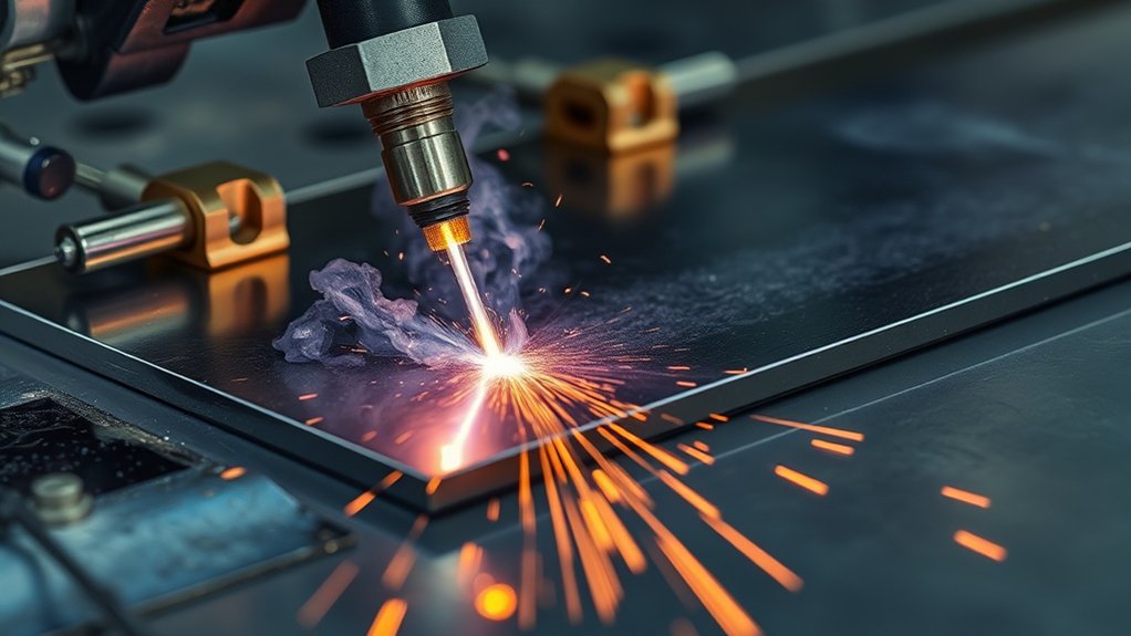
FineCut and Other Consumables for Narrow Kerf and Clean Edges
FineCut consumables are your go-to when you need a narrow kerf, low heat input, and crisp edges on thin steel. Tighter arc constriction, a reduced nozzle orifice, and tailored swirl rings shrink the heat-affected zone and limit distortion, which is the key advantage of FineCut for sheet work.
Match the cartridge, nozzle, and electrode set to the material gauge. Select amperage appropriate to thickness to hold kerf width and edge squareness. Validate with a straight-line test coupon, inspecting dross type (top vs. bottom) and edge bevel.
Match consumables to gauge, set amperage for kerf and squareness, then verify with straight-line dross and bevel checks.
Drive quality by optimizing travel speed. Faster feeds with FineCut typically polish the edge and shed dross. Run dry, clean air at correct standoff with a stable torch height to keep the arc column centered.
Consumable maintenance is non-negotiable: monitor nozzle orifice growth, electrode pit depth, and shield wear. Replace at spec limits. A worn tip destabilizes the arc, widens kerf, and heats the panel, increasing warp risk.
Log parts life and results for repeatability.
Speed and Amperage Settings to Minimize Heat Input
With consumables sorted for a narrow, stable arc, lock in heat control with the right speed and amperage pairing.
Target cutting efficiency by driving fast travel and conservative amperage adjustments. On 22 ga steel, run near 350 IPM to shed heat quickly while maintaining full penetration. The FineCut kerf keeps the arc stiff and localized, limiting thermal spread.
For 0.5 mm stainless, prioritize velocity. Faster IPM reduces dwell and curbs distortion. Undershoot amperage on thin stock to avoid over-energizing the puddle. Increase only until dross tails disappear.
1) Set baseline:
– 22 ga: start around 350 IPM with FineCut. Dial amperage at the low end of the torch’s thin-sheet range. Verify a clean, narrow kerf.
2) Tune amperage adjustments:
– Bump current in 2–5 A steps until the cut clears. Back off if edges blue or top spatter appears.
3) Stabilize thermal input:
– Use a water table to quench the kerf zone, flattening heat gradients and sharpening edges without sacrificing speed.
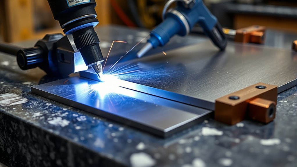
Fixturing and Clamping Techniques for Flat, Stable Sheets
Flatness is your control variable, and fixturing is how you lock it down before the arc fires. Start by screening stock. If a sheet is crowned or oil-canned, cold-straighten it with rollers or press blocks before loading.
Select fixturing materials with low thermal growth and good rigidity, such as blanchard-ground steel slats or MIC-6 plate, so the sheet stays planar under heat. Use clamping options that apply uniform, low-profile pressure: edge dogs, toggle clamps, or a vacuum table for full-surface hold-down. Keep clamp hardware outside the toolpath and pierce plume.
- Establish a grid: 150–200 mm clamp spacing on thin gauges.
- Use a torch height controller to hold standoff; flat support enables consistent arc voltage.
- Verify with feeler gauges; shim where needed to zero runout.
| Component | Purpose | Notes |
|---|---|---|
| Vacuum table | Full-area restraint | Minimizes micro-buckle |
| Edge clamps | Shear resistance | Low profile |
| Fixturing materials | Stable support | Low warp, ground |
| Height controller | Consistent standoff | Clean kerf, less heat |
Using Water Tables and On-Workpiece Cooling Methods
A water table sinks heat and captures plume, keeping thin sheet stable and minimizing warp while cutting.
Augment with on-piece cooling (submersion, a controlled water stream, or mist) paired with THC for constant standoff to preserve edge quality.
Run high traverse and ideal amperage/nozzle settings to limit heat input, manage kerf, and maintain geometry.
Water Table Benefits
Thin-gauge steel is prone to heat distortion, but a water table stabilizes the thermal profile at the cut zone and preserves flatness.
By absorbing and quenching heat right beneath the arc, the water table limits heat-affected zone growth, suppresses warp on 0.5 mm stainless, and improves edge fidelity.
You’ll also see lower dross because steam scrubs molten ejecta before it solidifies.
- 1) Submerged cutting: Keep the sheet just below the surface to manage heat buildup, reduce plume energy, and maintain dimensional stability without degrading arc integrity.
- 2) Pair with THC: Automatic Torch Height Control preserves standoff as sheet stresses relax, locking in kerf consistency and surface finish.
- 3) Speed synergy: Run high traverse speeds. The water bath removes residual heat, preventing propagation and cumulative distortion across small features.
Maintain clean water and correct table depth for repeatability.
On-Piece Cooling Techniques
Building on water table control of the heat-affected zone, on-piece cooling pushes thermal management directly onto the sheet to lock down flatness and kerf quality on thin steel.
Use on-workpiece cooling to deliver immediate heat reduction at the cut front. Dribble a controlled water stream ahead of the torch to quench nascent heat, suppress oxide color, and stabilize the kerf.
For stainless, submerge the panel just below the surface. The water jacket strips latent heat and reduces distortion from cumulative passes.
Pair cooling with Automatic Torch Height Control to hold standoff as the sheet relaxes. Consistent arc length preserves energy density and improves quench efficiency.
Run brisk feed rates to minimize dwell and thermal soak. Monitor steam, adjust flow, and maintain uninterrupted coolant contact through the toolpath.
Heat Management Best Practices
When thin stainless wants to potato-chip under arc heat, manage the thermal budget with water and speed. Use a water table as your primary heat sink: the bath wicks energy from the kerf, stabilizes 0.5 mm sheet, and suppresses distortion.
Pair it with high traverse (around 350 IPM on 22 ga) to minimize dwell and keep edges crisp. Add on-workpiece cooling methods like a light pour or fine mist to quench localized hotspots without shocking the cut.
1) Configure: Set water level just under the plate or partially submerge for maximum heat absorption. Guarantee drainage to avoid steam bursts.
2) Execute: Enable THC to lock standoff, preventing arc stretch that dumps extra heat.
3) Verify: Inspect kerf tint, dross line, and flatness. Adjust speed, amperage, and water exposure as needed.
Common Thin-Gauge Plasma Troubleshooting
Even with good settings, thin steel can throw problems. Here are common issues and how to fix them.
Excessive top dross: Usually means travel speed is too slow or amperage is too high. Increase IPM in small steps or drop current by 2–3 A until the dross clears.
Bottom dross or whiskers: Travel speed may be too fast, or the arc isn’t fully penetrating. Slow down slightly or bump amperage just enough to achieve a clean exit.
Wavy or uneven kerf: Often caused by inconsistent torch height. Check your THC calibration, clean the torch slide, and verify the sheet is flat and properly fixtured.
Edge bluing or discoloration: Too much heat is reaching the cut edge. Increase travel speed, lower amperage, or add water cooling. Confirm that consumables aren’t worn.
Arc starting issues on thin stock: Make sure consumables are fresh and that your pierce height is set correctly. A pilot arc that doesn’t transfer cleanly can blow holes in thin material.
Cutting Strategies: Lead-Ins, Pierce Delays, and Path Planning
Before you strike an arc, lock in your cutting strategy to control heat, kerf, and edge quality on thin steel. Apply lead-in techniques to enter off-part, then traverse into geometry. This shifts the pierce crater away from the feature and stabilizes the arc.
Pair that with pierce optimization: set pierce delay just long enough to fully penetrate without overheating. Too short, and heat blooms at the surface. Too long, and it undercuts the start and weakens the edge.
Run fast traverse and cut speeds to evacuate heat, using fine cut consumables for a tighter kerf and higher arc density. Sequence parts to minimize cross-sheet travel and avoid revisiting hot zones. Start with small internal features, progress outward, and finish with perimeter cuts last.
| Control | Setpoint Guidance | Result |
|---|---|---|
| Lead-in length/angle | 0.1–0.2 in, 30–60° | Clean entry, off-feature crater |
| Pierce delay | Just to break through | Stable start, minimal heat |
| Cut speed | High, per chart + test | Reduced HAZ, less warp |
| Path order | Inside-out, cool zones | Thermal balance, accuracy |
Post-Cut Cleanup: Minimizing Dross and Edge Finishing
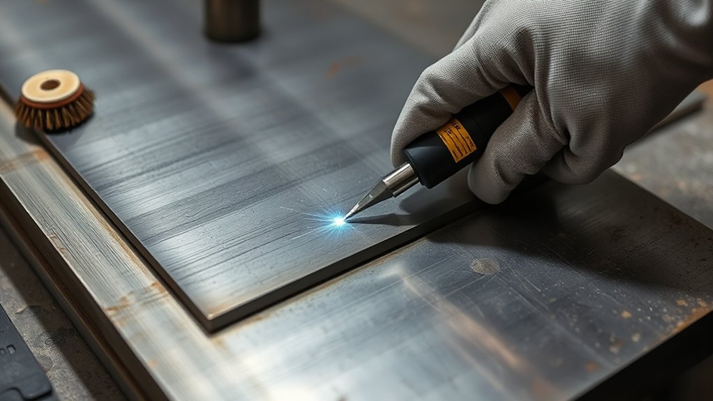
A clean cut starts at the torch, but post-cut cleanup locks in finish quality by managing dross and refining edges with minimal rework. Start by verifying cut parameters (amperage, arc voltage, and traverse speed) to limit molten rollover.
Faster travel and fine cut consumables narrow kerf width, reducing secondary dross removal and simplifying edge refinement. A water table helps quench the plume, trap particulate, and contain slag for cleaner post-cut handling.
Use a methodical sequence:
1) Bench prep: Deburr lightly with a scraper or chisel to knock off brittle dross without gouging the heat-affected zone.
2) Mechanical finish: Run a flap disc on an angle grinder, following the cut path to blend micro-notches and normalize edge land. Keep passes light to avoid heat-loading.
3) Final spec check: Inspect edge squareness, kerf taper, and surface profile. Re-touch high spots and verify fit-up.
Dialing in settings upstream minimizes cleanup time. Disciplined grinding delivers consistent cosmetic and dimensional results.
Safety Practices for Handling Thin, Sharp, and Hot Parts
With edges dressed and parts inspected, shift focus to handling hazards that follow a clean cut. Enforce safety training so you and your crew apply protective gear and handling protocols every time.
Wear heavy-duty gloves to prevent lacerations from razor-sharp edges and burr-laden corners. Fit safety glasses or a face shield to block sparks and micro-debris. Wear reinforced boots and flame-resistant apparel. Recently cut thin steel retains heat and transfers it quickly through contact.
Stage parts on heat-tolerant surfaces and confirm temperature with a contactless thermometer before moving. Use tongs, magnets with rated lift, or edge clamps to keep hands clear. Apply proper lifting mechanics: neutral spine, close load, team lift or mechanical assist for large plates.
Maintain a clear deck. Purge clutter, route leads overhead, and mark hot zones with signage. Brief all personnel on sharp and hot material hazards, and validate compliance with documented checklists. For a full overview of plasma cutting safety standards, refer to the AWS Z49.1 Safety in Welding, Cutting, and Allied Processes guidelines.
Frequently Asked Questions
Can I Cut Painted or Coated Thin Steel Without Damaging the Finish?
Yes, but you’ll need specific process controls. Mask edges, control amperage, increase standoff, and use fine-cut consumables. Pre-score lines, reduce the heat-affected zone, and apply localized cooling. If necessary, strip paint from the cut zone afterward.
How Do Ambient Temperature and Humidity Affect Thin-Sheet Plasma Cutting?
Ambient temperature and humidity directly influence cut quality. Moisture causes nozzle sputter, porosity, double-arcing, and dross. Preheat cold stock, dehumidify intake air, use desiccant dryers, verify dew point, and recalibrate amperage as conditions change.
What File Formats and CAM Settings Work Best for Tiny Features?
Use DXF or SVG file formats with simplified nodes. In your CAM software, configure kerf compensation, lead-ins of 0.02–0.05″, minimal pierce delay, cut height of 0.06″, feed rate tuned to amperage, corner slowdown of 30–50%, micro-tabs of 0.02″, and optimized toolpath order.
How Loud Is Thin-Sheet Plasma Cutting, and What Hearing Protection Is Ideal?
It’s loud. Noise levels typically hit 95–115 dBA at the torch and 85–100 dBA on the operator side. Use double protection: foam earplugs (NRR 32) plus over-ear muffs (NRR 25–30). Verify seal, fit-test, and monitor exposure with dosimetry.
Can I Safely Stack-Cut Multiple Thin Sheets, and How to Separate Them?
Yes. You can stack-cut thin sheets if you clamp them, tack corners, and use dry, flat, de-burred stock. Use interleaf shims to control arc blow. For separation, wedge and pry, then flex, slide putty knives in, and deburr.
Conclusion
You have the full playbook now: dial amperage low, push traverse high, ride the arc on-height, and let FineCut tips slice a razor kerf. Lock the sheet, flood the heat with water or air, and plan toolpaths with crisp lead-ins and tight pierce delays. Keep consumables fresh, gas dry, and THC responsive. Do this, and thin steel behaves. No potato-chip warp, just laser-straight edges. You’re not cutting metal. You’re conducting heat, precisely and repeatably.